- Capabilities
-

CNC Machining
Tight tolerance and 20+ finishes 3, 4 , 5 axis, as fast as 2 days -

Sheet Metal Fabrication
High-precision, on-demand sheet metal cutting and bending. -
3D Printing
SLA, SLS,MJF,SLM, FDM 3d printing with post treatment. -

Vacuum Casting
Production quality parts without the tooling investment.
-
- Solutions
Rapid Prototyping
Fastest lead time of high-quality prototypes at minimal cost.

Low Volume Production
From one-off prototyping to low-volume production.

Mechanical Assembly
Custom assembly for project-specific needs.

Custom Package
Ready to help you prompt your brand.
- Sources

Materials
Select from 100 more types of metals and plastics.

Finishes
Select from 20 more types of surface fishes.

Industries
Providing precision machining and manufacturing solutions.

Cases
How we assist our clients in bringing their projects to fruition.
- Company

Quality Assurance
Consistent quality, every time.

About Us
Your go-to manufacturer for custom parts.

Newsroom
Learn updated news about ECOREPRAP.
Technical Drawings for CNC Machining: The Complete Guide
Updated: December 02, 2023
Introduction
Technical drawings are the instructions that tell a CNC machinist how to make a part. They can be created using CAD software, or they can be hand-drawn. Once the technical drawing is complete, it is saved as a PDF and sent to the CNC machine. The CNC machine reads the PDF and knows how to make the part.
In this post, we will explain the main part for technical drawing and several tips for adding dimension, tolerance, and Annotations.
1. Why Technical Drawing Is Important
Technical drawing has been important since the beginning of design. It has been done by hand since people began creating parts, but today it can be automated using design software. When the designer has a plan, it is communicated to the machine with technical or engineered drawings. These drawings contain 3D or 2D information about the part.
Other data included in technical drawings are any finishing instructions, the dimensions, the size, shape, and color, the surface finish, the part usage, and more. A machinist can use the technical drawing alone to create the part accurately.
The technical drawings are a critical component of creating the 3D model in CNC machining. You can pre-program the machine with the 3D CAD design, and the technical drawing is used for the details. For example, when you machine screws or nuts, the threads are detailed and need to be precise. The technical drawing makes this possible.
In addition, technical drawings offer both an isometric view and a detailed section-based view. The machinist will have detailed information about annotations, tolerances, dimensions, and other aspects of the part. Technical drawings also help with depth, sinks, and details for hole drilling.
Technical drawings play an important role in the manufacturing process for the following reasons:
- Your technical drawings describe features that don’t come through in a 3D CAD model. This includes internal and external threads.
- Manufacturers develop a comprehensive understanding of the requirements of the part through dimensions, annotations, and tolerances.
- Technical drawings allow designers and engineers to provide manufacturers with specific instructions for any special requirements, including finishing and surface roughness.
- No matter how simple or complex your part design is, most manufacturers will refer to them throughout the manufacturing process.
2. Components of Technical Drawing
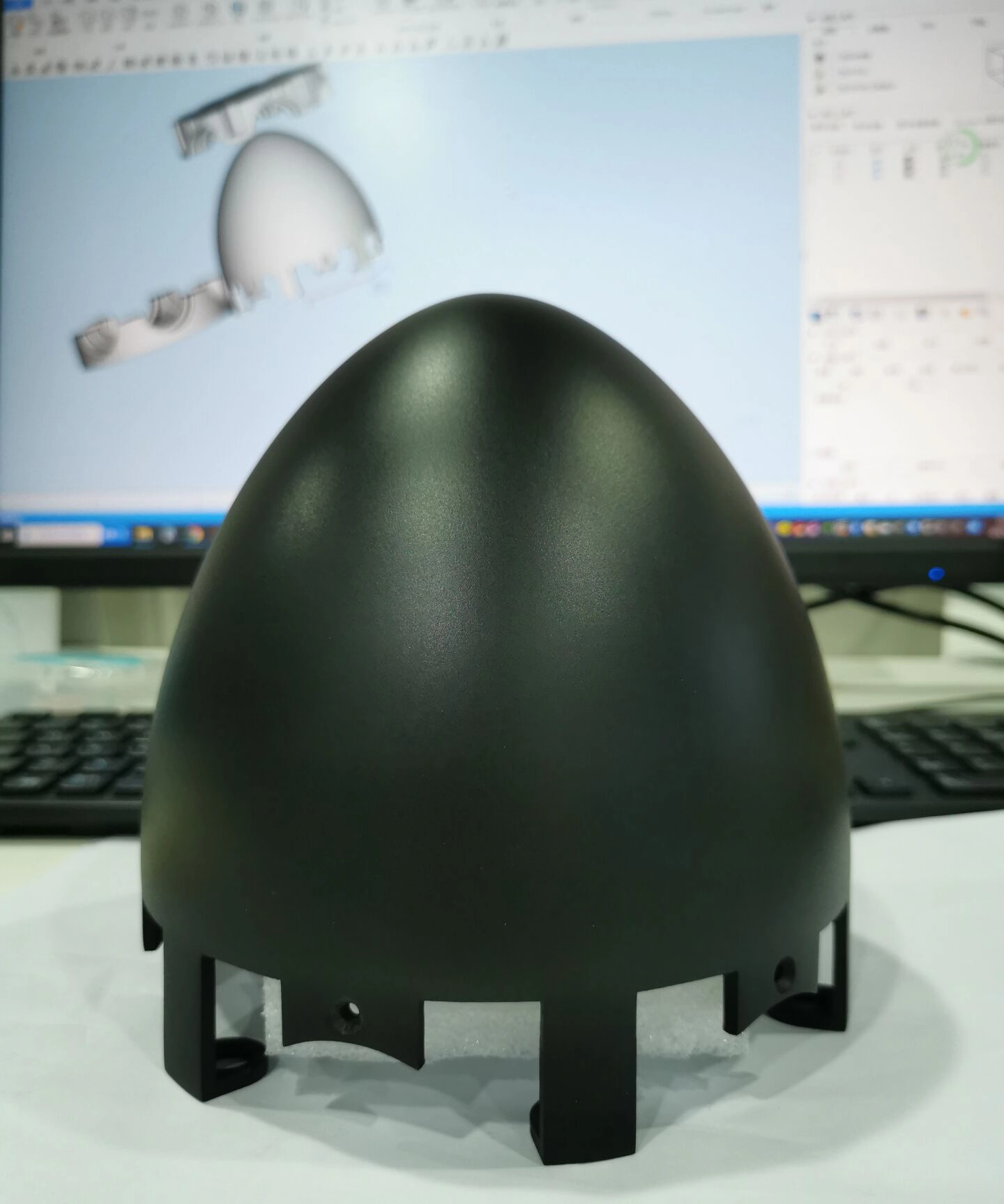
There are several components that are part of technical drawings. Among the most important components are the title block, the isometric view, the orthographic view, the coordinates, the section view, and the detail view. These aspects of the technical drawing provide details to the manufacturer and allow you to communicate all of the requirements for your part to the manufacturer. Take a look at the following:
Title Block
The title block contains all of the basic information about the part that is going to be produced. It is located in the bottom right corner of the document and includes the name of the part, the company name, the part number, any requirements for materials and finishing, and other important details.
The title block also contains technical information about the part to be made, including surface finish requirements, the angle of projection, system measurements, material, and scale. The engineer or designer who rates the title block can customize the structure and format as much as needed.
Isometric View
Another component of technical drawings is the isometric view. This is the picture view that renders the 3D representations of the part that is being made. 3D representations enable the reader to gain a greater understanding of the part because it is a pictorial representation that shows depth.
An isometric view isn’t necessary for all parts, but providing it helps the manufacturer to understand the geometry of the part better. Moreover, it can provide additional data about the part, such as the direction of installation or the build orientation.
Orthographic View
The orthographic views offer data about the geometry of the part that needs to be produced. It is the 2D view that is known as the primary view. It represents the sides of the object, including the front, left side, right side, top, bottom, and rear.
This view of the 3D object focuses on the features, tolerances, and dimensions. For many parts, two to three orthographic views are enough to show all of the geometry of the part. An orthographic view is a 2D representation of the 3D part from these different points of view.
Coordinates
The coordinates are an important part of technical drawings, as they are the reference points. They are used with larger parts or parts with complex features, and they are located along the borders of the drawing to make it easier to visualize the part that is being produced. They also function as points of reference in communications about the drawing.
Section View
The section view is made by showing a 2D representation of the part after it has been cut through. In other words, it is a slice through the part. This allows a view of the internal features, which are not seen in either isometric or orthographic views.
It will show a cross-section that is along the cut plane that is specified. Section views are frequently positioned in line with the orthographic view; you can place curing lines on the orthographic view to show where the part will be sliced for the section view.
Detail View
The detail view shows the specific details of the orthographic view. This is important when you have orthographic views that have areas that are difficult to dimension. You can place a detail view anywhere in your drawing, and you indicate it with a single letter that shows which area of the orthographic view is being referenced.

3. How to Prepare Technical Drawings for CNC Machining
When you are preparing technical drawings for CNC machining, it is important to follow these steps. Take a look at the following:
- First, you need to define the views according to the requirements for the part. Make sure that the orthographic projection is in the center of the drawing so that you have enough space for the dimensions.
If the parts have areas that are difficult to access or internal features, you need to create section views or detail views. - Next, you should create construction lines for all of the views. You should include any centerlines for defining planes or axes of symmetry, center marks, and center mark patterns that define the location of circular patterns or hole centers.
- The next step is to create the dimensions for your drawings. Begin with the most critical dimensions and continue until they are added.
- Then, you need to determine the size, length, and location of any threads in the drawing.You should apply the standard tolerances to all of the features. Make sure that you include additional tolerance information for any features that require a higher degree of accuracy.
- Make sure that you fill in the required title blocks and any relevant information correctly and accurately. This includes special instructions concerning the surface finish and deburring, as well as any other important notes for the manufacturer.
It is important to make a note of any information that is outside of standard practices. It is critical to make sure that you specify any dimensions, annotations, and tolerances for your technical drawings.

4. Useful Tips for Adding Dimension, Tolerance, and Annotations
After you complete the design for your parts using a 3D CAD file, it can be difficult for the machinist to check the dimensions on the technical drawings. You can take steps to make this process easier and reduce some of the more serious errors in manufacturing.Take a look at the following tips for adding dimension, tolerance, and annotations:
- Make sure that you place dimensions on all relevant parts.
- Add dimensions critical to function to all parts.
- Add dimensions to other features as well, and make sure that they are placed correctly and have descriptions that are both readable and clear.
- If you have repeated features, include the number of repeat features in the view and add only one dimension.
When you specify tolerances, you will include the range of variation from the original dimensions that is acceptable. If you have two components that may have feature interference, this feature is critical. There are different formats for tolerances, and they can apply to all dimensions of your technical drawing.
The bilateral tolerances are the simplest, and they are also the most popular. They are symmetrical around the base tolerances as+/-0.1mm. You only need to use tolerances when the technical drawings exceed the standard values.
5. Final Words
It is important to understand technical drawings and how they relate to CNC machining. Using these drawings allows the machinists to produce parts that are precise and makes the process much easier. The end result is products that function properly.
If the technical drawings aren’t accurate, it may cause delays in production and increase costs. The best way to avoid errors in technical drawings is to make sure that you work with CNC machining service company.


