Updated: May 11, 2024
Polyurethane CNC Machining in kind of a challenge because of its elastic properties. In this blog, we will give more information about how to get perfect CNC machined PU parts.
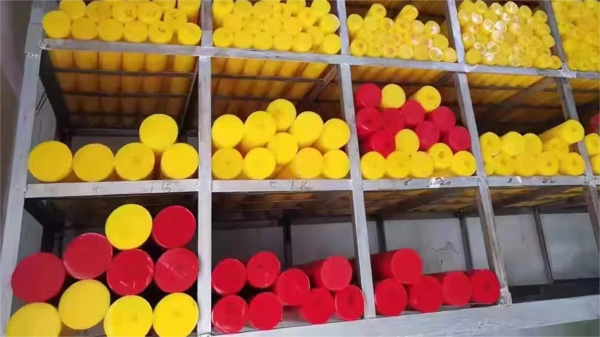
With hardness from Shore 90A to 75D can be milled successfully. However, we would not recommend the PU below 80A for CNC machining.
| Tool | Speed | Feed Rate |
| Two fluted end mills Single point fly cutter | 900-1300 | 15-20 inches/min |
When turning polyurethane, especially for large polyurethane parts, the key principle is to ensure that the lathe operates at high speeds. This is particularly crucial for PU with hardness below 90A. It is advisable to set the lathe to the maximum speed. The choice of cutting tools is also of utmost importance, and it is recommended to use high-speed steel tools.
Turning, facing, and boring tasks are executed on either a turret or engine lathe. The choice of tool configuration, geometry, placement, and speed is contingent upon both the hardness of the urethane and the specific operation chosen.
Nominal Turning Conditions:
| Shore A Hardness | Cutting Speed ft/min | Feed in./rev. | Tool Shape | Surface Roughness Microinches |
| 78A-88A | 1,000 – 1,650 | .004 – .008 | 12 53 25 | 50 |
| 89A-95A | 330 – 500 | .004 – .008 | 12 53 25 | 20 |
| 50D-60D | 330 – 500 | .004 – .008 | 12 53 25 | 10 |
PU machining-facing:
The guidelines for facing board parts align with those for turning. When cutting thin discs, it is recommended to use a cutting tool with a highly acute blade, approximately 15 degrees including angle. Due to the heat generated from friction, it is advisable to incorporate cooling during the process.
PU machining-boring:
For boring, standard tools are employed at cutting speeds ranging from 130 to 170 ft./min., with the feed kept as slow as possible (approximately 0.0004 to 0.0012 in./min.). A higher speed can be applied for harder materials. Hole depths up to one inch can generally be achieved without the use of coolant. For materials below 80 Shore A, the hole diameter will be up to 4% less than the drill diameter.
PU machining-knifing:
When precision-knifing urethane with close tolerances, it is crucial to utilize a tool that is razor-sharp and as thin as possible.
| Shore A Hardness | Tool | Turning Speed RPM | Feed Rate |
| 70A-95A | High Speed Steel | 600-1000 | Rapid,had |
| Below 70A | Ground Carbide | 600-700 | Moderate to rapid,hand |
A highly effective machine for cutting urethane is the band saw. Longer blades, ranging from 125 to 175 inches, contribute to cooler operation, preventing urethane from melting during the process.
A recommended blade type is the hook-type tooth blade, approximately 0.75″ wide by 0.030″ thick, featuring fourteen teeth per inch, which has demonstrated excellent performance. Surface speeds of 200 ft. per minute are suitable for all hardness levels.
For achieving a finer finish, it is advisable to use a blade with ten teeth per inch. When cutting urethane with a hardness of 90 Shore A and below, employing a spray mist of water-soluble oil proves effective in minimizing heat buildup and enhancing the final finish.
Slow spiral drills are recommended for drilling operations. This ensures the efficient discharge of chips with minimal binding and heat buildup.
Utilizing sharp cutting edges is imperative, and polished flutes improve chip clearance. Coolant is essential for optimal drilling performance.
To enhance drilling performance, the rake angle should be reduced to a 0-degree angle, and a generous lip clearance (approximately 16 degrees) should be provided for proper relief.
For heavy walls and large diameters, sharp points with angles of 90-10 degrees are ideal, while blunt angles (15 to 130 degrees) work better for thin walls. Achieving close tolerances requires feeds in the range of 0.004 to 0.006 inches per revolution (ipr).
Achieving smooth surfaces involves using carborundum grinding wheels with fine grain size, medium hardness, and a coarse texture. An effective choice is a 6″ x ¾” Simonds wheel with the specification C60-J-7B-3. Optimal performance is typically achieved within a wheel RPM range of 2,200 to 3,500.
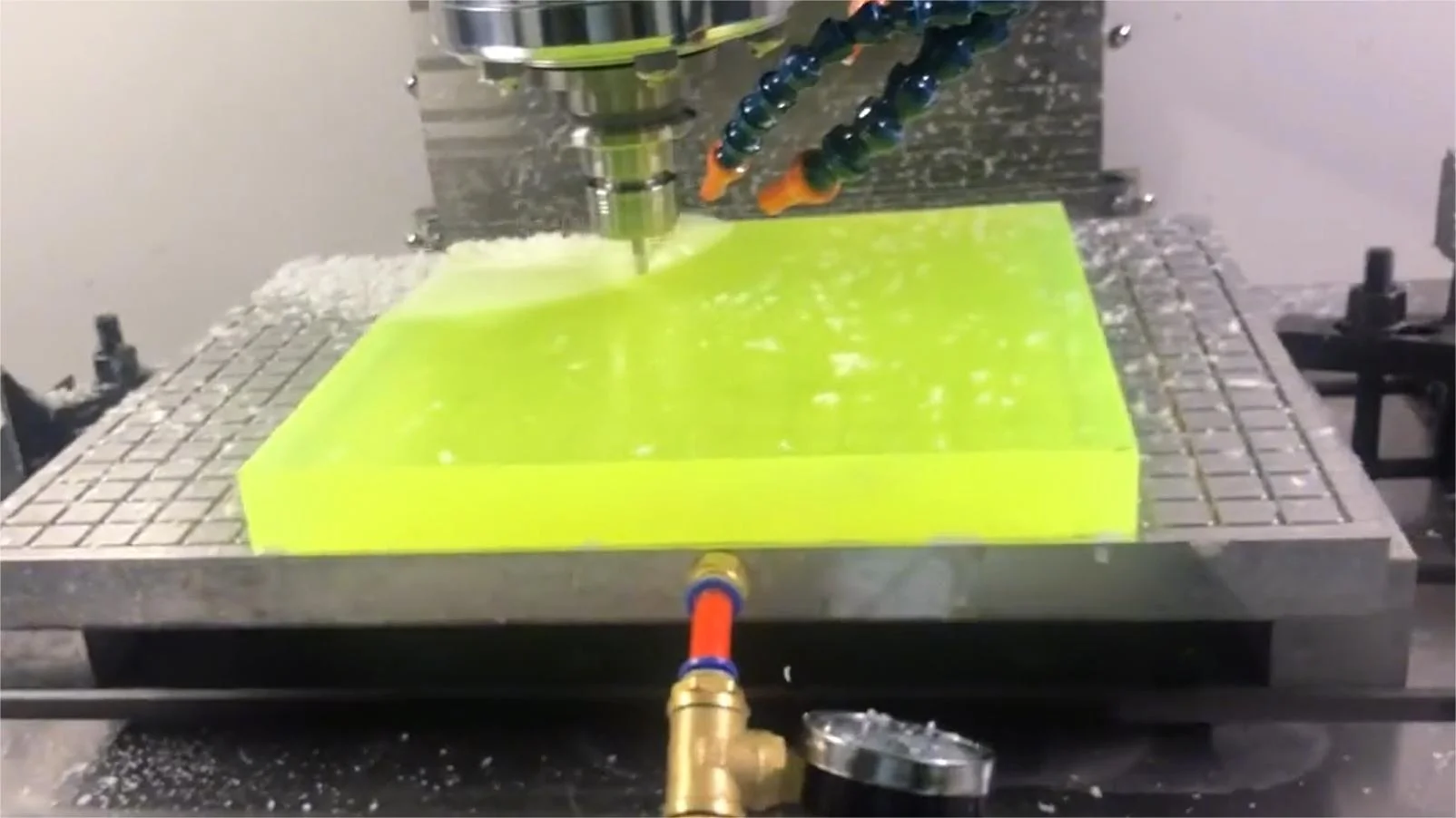
Above, we outlined the characteristics of each machining process for PU. At ECOREPRAP, we possess extensive experience in PU turning and milling on CNC machines. When machining PU, it is essential to consider the following aspects.
Tool Selection
Choose tools with sharp edges, good rigidity, and some level of toughness due to PU’s lower hardness and wear resistance compared to metals. This helps prevent rapid tool wear or chipping.
Optimal tool shapes and angles should be selected to minimize cutting resistance and heat generation. Given the moderate hardness of PU, sharp tools like high-speed steel or tools used for aluminum machining are commonly employed.
For air-cooling, recommended parameters include a speed of 6000 RPM, feed rate of 1500-3500, and a cutting depth of 0.5. These parameters are suitable for holes and features.
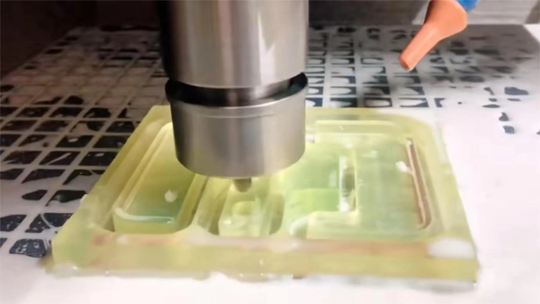
Water-cooling allows higher speeds, as efficient cooling aids in rapid part cooling. Machining is often performed in climb milling, leaving a bottom allowance of 0.3 during vacuum clamping to avoid cutting through.
PU machining generally does not require cutting fluids or oils.
Due to PU’s elasticity, careful attention is needed during clamping to ensure sufficient clamping force without causing material rupture or deformation.
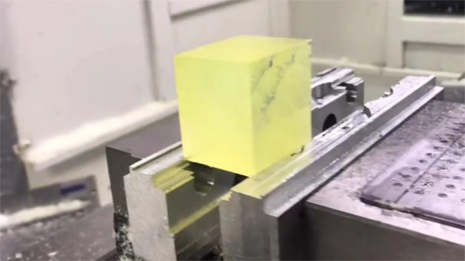
Various clamping methods can be considered, such as vacuum clamping for larger sizes, double-sided tape and screws for smaller sizes. Vise grips can be employed for clamping. When using vise grips, it’s essential to choose appropriate machining parameters based on the clamping force (small cutting depth and rapid feed).
For adhesive performance, when using double-sided tape, ensure that there is minimal residue of coolant and oil on the fixture. Electric wood adheres more securely than aluminum alloy.
To prevent material lift during machining, especially for thin walls, consider reinforcing the PU by applying hot melt adhesive or epoxy around the material’s outer edges.
After machining, residual chips can be removed using a brush or coarse sandpaper.
PU’s high material removal rate requires careful planning of toolpaths and allowances to prevent excessive tool loads or workpiece deformation.
Consider a two-step machining approach with a 0.5 allowance for roughing and a ball-end mill with a step distance of 0.15 for finishing.
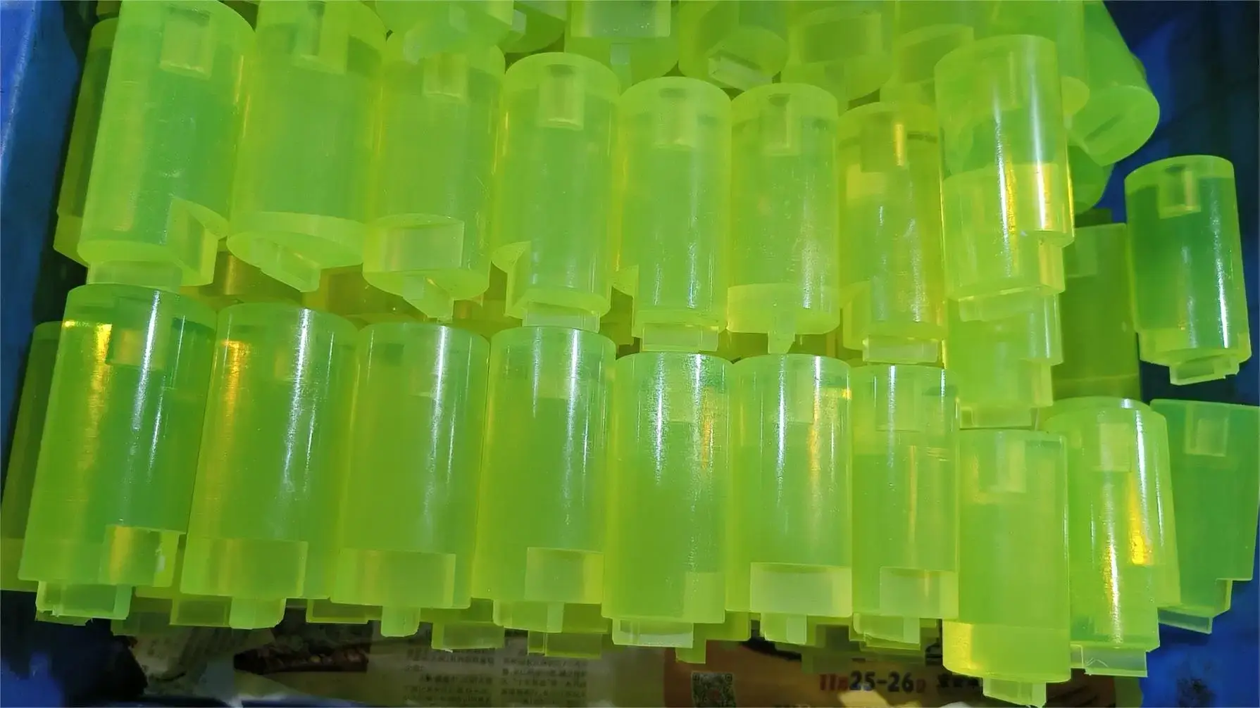
While machining PU poses certain challenges, by following the machining guidelines provided above, we believe that everyone can successfully CNC machine qualified PU polyurethane prototypes or batch parts. Alternatively, you can opt for experienced CNC machining services to assist you in completing the machining process.