 Below is a square corner in 3d model.
The geometric shape of the milling tool is the root reason why internal CNC corners cannot be truly square.
CNC milling primarily relies on End Mills for cutting. Since an end mill is cylindrical, its cutting edge is naturally round.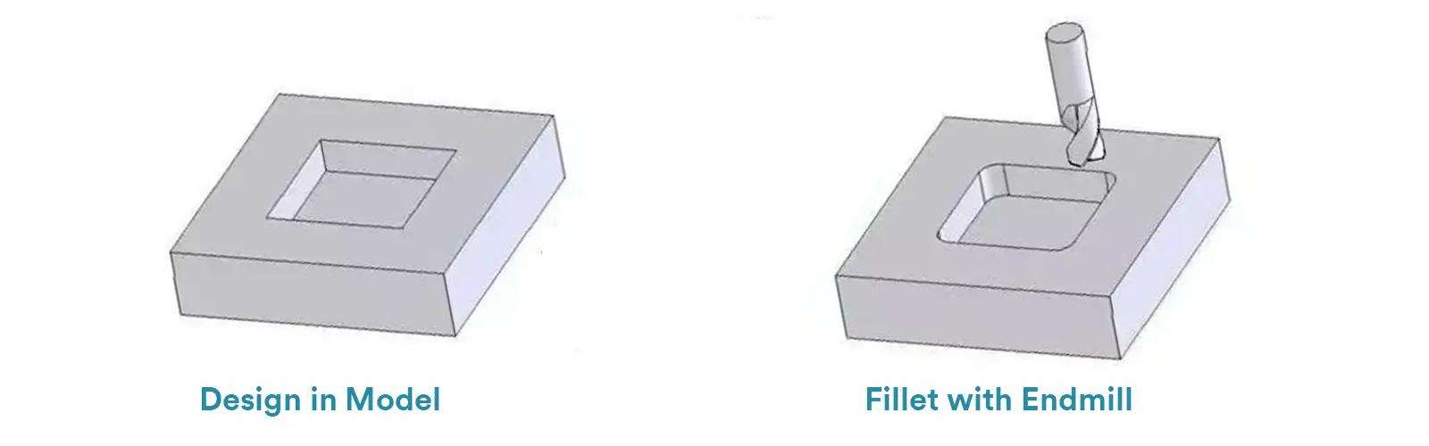
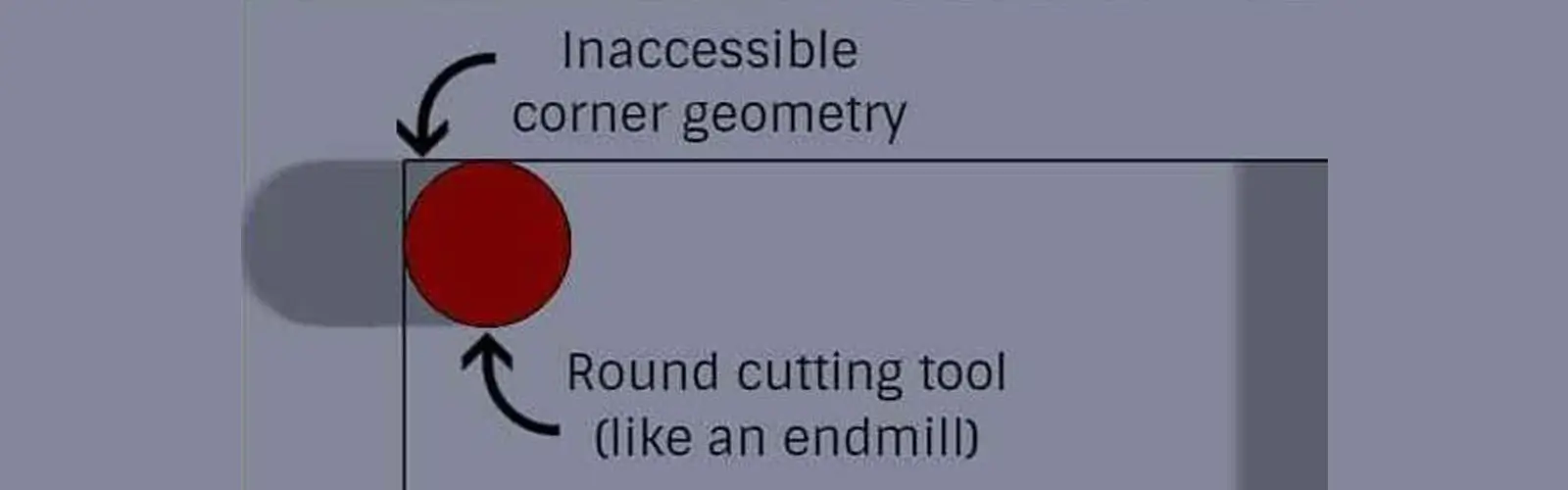 When a round tool cuts along two intersecting planes, it is physically impossible for the tool to reach the absolute corner. It will inevitably leave a circular arc (a fillet) in the corner with a radius equal to the tool’s own radius.
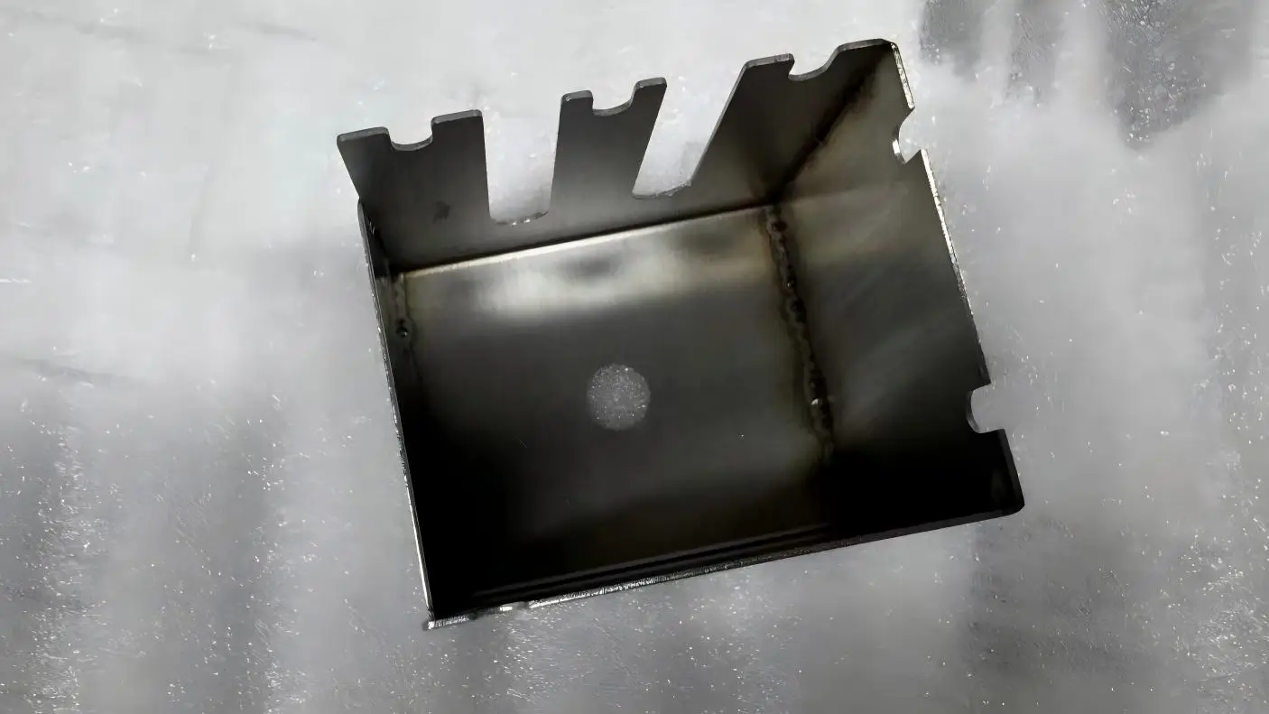
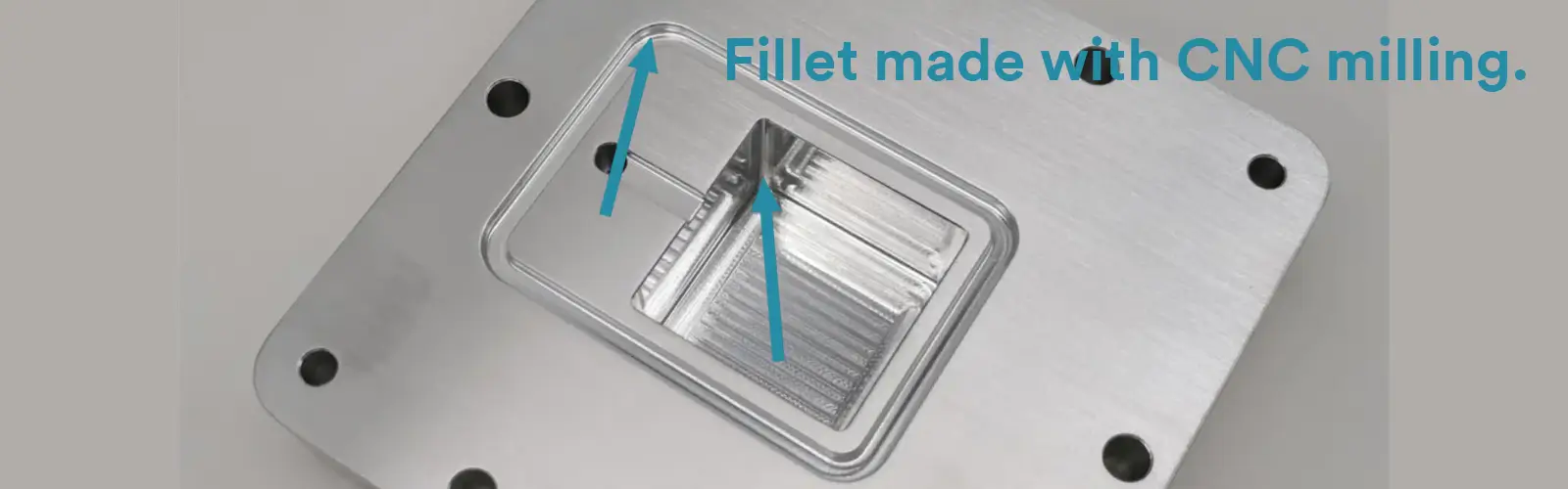
See a milled part with fillet below.
Attempting to achieve a near-sharp corner (e.g., R0.1 mm) requires using extremely small micro-tools. This path is financially prohibitive because:
Tools Break Easily: Micro-tools are highly fragile, leading to high scrap rates and wasted material.
Time and Cost Skyrocket: They must run at extremely slow speeds, which drastically increases the machining time and overall cost of the part.
Even if the physical challenge could be overcome, creating a sharp internal corner is structurally unsound from an engineering perspective.
A sharp internal corner (theoretically R0) acts as a geometric stress concentration point. When the part is subjected to a load, the localized stress at this corner increases dramatically (theoretically approaching infinity).
For critical parts that endure cyclical loading (fatigue), stress concentration is a recipe for disaster, causing cracks to initiate and the part to fail prematurely.
Therefore, rounding the corner with a Fillet is the optimal engineering solution. The fillet’s job is to smoothly disperse stress, allowing the high-stress area to transition uniformly to the adjacent surfaces, which significantly boosts the part’s fatigue life and overall reliability.
Related blog: Fillet vs Chamfer
While fillets are generally preferred in CNC machining, there are several critical situations where a sharp 90-degree internal corner is essential for functionality, precision, or safety.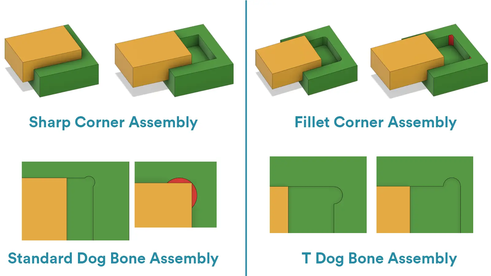
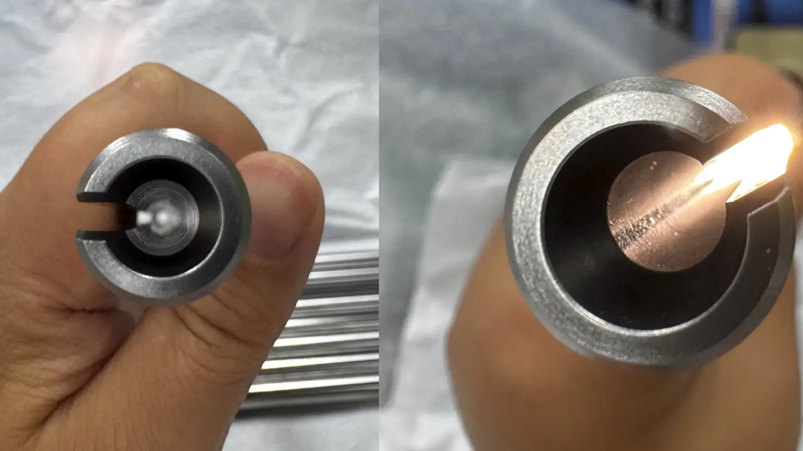
In applications requiring perfect mating between components—such as a square protrusion fitting into a corresponding cavity—sharp corners are indispensable. This precise, zero-gap assembly is crucial for:
For example, in mold bases or precision machinery where components like bearings, slides, or locating blocks must fit perfectly against flat surfaces, any fillet—no matter how small—would create a gap.
This compromises positioning accuracy, reduces stability, and can lead to premature wear or failure.
In tooling, fixtures, and measuring equipment, sharp internal corners often serve as datums—precise reference points that define the part’s coordinate system. A true 90-degree corner provides the most accurate and repeatable location from two intersecting planes.
A rounded corner introduces uncertainty and variation, making it impossible to meet strict Geometric Dimensioning and Tolerancing (GD&T) requirements. For high-precision applications where consistency is paramount, only a sharp corner ensures reliable and repeatable positioning.
Perhaps the most demanding application for sharp internal corners is in sealing systems. When a groove is designed to house a square- or rectangular-cross-section gasket, the groove must feature sharp corners to ensure:
If the groove has rounded corners, the gasket will not compress properly in those areas, creating potential leak paths. In applications involving pumps, valves, or battery housings, such leakage constitutes a critical functional failure.
When the design absolutely requires a sharp inside corner (square corner or 90°), traditional CNC milling tools alone won’t be enough.
In such cases, there are three main strategies: two involve specialized, high-cost machining methods to physically cut the corner, and one is a design workaround that avoids cutting a sharp corner altogether.
EDM is the ultimate solution for creating sharp corners, acute angles, or complex geometries in areas that CNC milling cannot reach.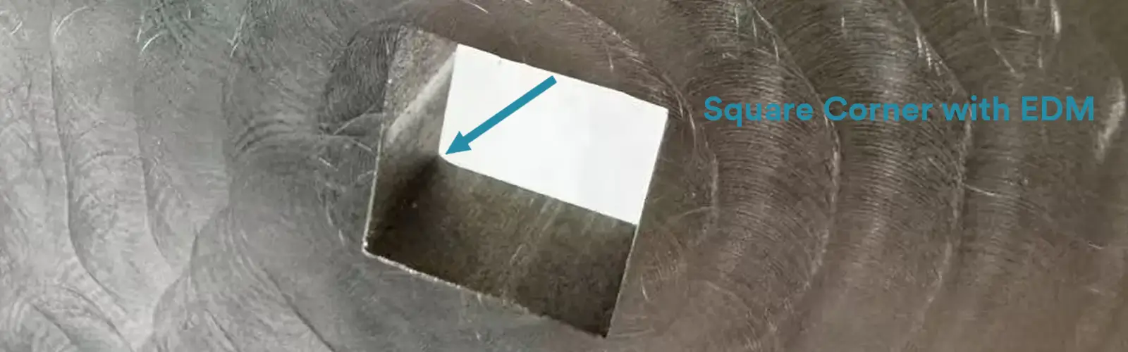
By using controlled electrical sparks to erode material, EDM can achieve precise, sharp features in areas inaccessible to milling cutters.
Both wire EDM and sinker EDM can make internal sharp corners.
The Difference Between Wire EDM and Sinker EDM for Creating Square Corners
| EDM Method | Principle of Operation | When to Use It | Advantages | Disadvantages |
|---|---|---|---|---|
| Wire EDM | Uses a thin copper wire (electrode) to erode conductive material via electrical discharge, essentially “burning” the material away. | For through-features (cuts that go all the way through the part). | Can cut a perfect 90∘ corner. The internal radius is only limited by the wire diameter (achievable down to R0.05 mm). | Can only process conductive materials. It’s a secondary process: the rough shape must first be milled by CNC before wire cutting is performed. It is extremely high cost and very slow. |
| Sinker EDM | Uses a precisely pre-machined graphite electrode tool (negative shape) that is submerged into the part to remove material via electrical discharge. | For blind-features (pockets or holes that do not go through the part). | Can create precise, difficult-to-mill blind square corners in pockets. | The electrode mold itself requires precision manufacturing. It is extremely high cost and very slow. |
If the corner goes all the way through the part, use Wire EDM. If the corner is in a blind pocket, use Sinker EDM.
This is a corner-cleaning technique used on a CNC milling machine, designed to minimize the fillet radius in internal corners.
When it comes to achieving sharp internal corners, traditional CNC milling often leaves a small fillet behind. Micro-tool corner cleanup is a clever way to minimize these fillets without resorting to expensive EDM.
How It Works:
After completing the main machining, a tiny end mill—sometimes as small as Ø0.5 mm—is used to carefully trace the internal corners. This removes leftover material and reduces the fillet radius as much as possible.
Advantages:
Cost-effective: Avoids the need for secondary EDM processing.
Precision: Can achieve very small fillet radii, for example, R0.2 mm, making it suitable for detailed, high-precision parts.
Limitations:
Fragile tools: The tiny end mills are delicate and require very slow feed rates, which can increase machining time.
Radius limitation: Only small fillets can be achieved; a perfect sharp corner (R0) is not possible.
When to Use It:
Micro-tool corner cleanup is ideal for projects that require high-precision, small-radius internal corners without the added cost of EDM. It’s especially useful in CNC machining for electronics, aerospace, and intricate mechanical components—just be mindful of the slower machining speed and the risk of tool breakage.
The Dog-Bone Fillet is the most common and most economical solution used by CNC engineers when a part must mate with an external 90∘ component.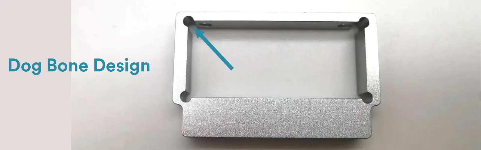
Instead of trying to force the internal corner into a 90∘ angle, the Dog-Bone method involves machining a small, circular recess outward from the corner where the two adjacent planes meet.
When an external 90∘ block is inserted into the cavity, the sharp tip of the block simply falls into the circular recess, bypassing the cavity’s natural fillet. This allows the straight edges of the block to contact the cavity walls completely, resulting in a zero-gap assembly.
Advantages: It is cost-effective, requiring only simple circular interpolation (G02/G03 codes) on a standard CNC mill, utilizing standard tools.
Drawback: The internal corner is not a true 90∘ angle. The visible circular recess is an engineering compromise that must be accepted in the final design.
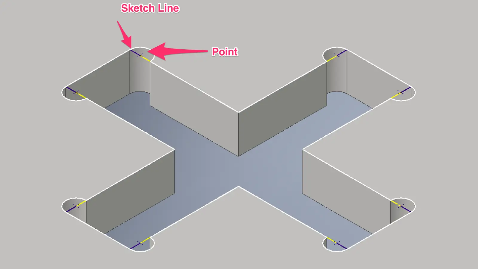
Key Design Considerations:
The radius of the Dog-Bone recess (RDog-Bone) must be greater than or equal to the radius of the original internal fillet (RFillet).
The depth of the recess must be sufficient to ensure the 90-degree tip of the external part clears the internal corner completely.
In practice, the term “Dog-Bone” is a catch-all for these corner-relief features. Engineers often break the design down into two main “forms” based on geometry and manufacturing goals: the Standard Dog-Bone and the Tangent Dog-Bone.
Standard Dog-Bone
This is the most common form, easiest to program, and simplest to inspect.

Simple Programming: Only requires standard G02/G03 circular interpolation.
Easy to Inspect: The recess is a full circle, making it simple to check with standard tools.
Reliable Function: Guarantees a zero-gap fit.
Tangent Dog-Bone
This form is more geometrically challenging but is designed to minimize material removal.
Aesthetic (Relatively): The recess is smaller, minimizing the visual impact on the geometry.
Strength Preservation: Since less material is removed, it theoretically weakens the surrounding structure less than the Standard Dog-Bone.
Choosing Between Standard and Tangent Dog-Bone
For most projects, the Standard Dog-Bone is the way to go. It gets the job done simply, reliably, and for the lowest cost.
But if your design is in the spotlight or every bit of strength counts, the Tangent Dog-Bone (T-Bone) is the smarter choice. It offers a more discreet and structurally sound solution.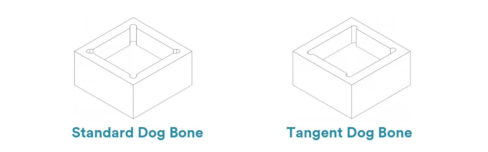
Dog-Bone Fillet Comparison: Standard vs. Tangent
| Feature | Standard Dog-Bone | Tangent Dog-Bone (T-Bone) |
|---|---|---|
| Primary Goal | The simplest and fastest way to eliminate interference. | To preserve as much material as possible, minimizing impact on part strength. |
| Visual Look | A full, circular notch at the corner—like a small, round hole. | A slender, crescent-moon shaped slot that hugs the side walls. |
| Key Geometry | The center of the circular notch lies on the extended lines of the walls. | The center is defined by the points where the arc tangently meets the walls (a bit more complex). |
| Assembly Fit | Perfect, zero-gap fit. The external part’s corner sits neatly in the circular space. | Perfect, zero-gap fit. Achieves the same functional result but with less material removed. |
| CNC Cost & Effort | Low. Simple to program with straightforward toolpaths. | Medium. Requires more precise programming to correctly machine the tangent points. |
| Impact on Strength | Slightly Higher. Removing a full circle of material has a modest impact. | Minimal. Theoretically weakens the surrounding structure the least. |
| Ideal Use Case | The go-to choice for most applications. Fast, reliable, and cost-effective. | Best for thin-walled parts or high-strength applications where every bit of material counts. |
Although not commonly used, there are two additional ways to achieve near-perfect right angles in internal corners:
This method uses a specialized tool with a cutting edge on its tip and side, allowing it to reach underneath and undercut the material. It can create a corner that is much closer to a true 90 degrees.
But this process puts more stress on the delicate tip of the tool and requires a very rigid machine setup. It’s a more advanced technique that demands greater skill and care.
This is a low-tech method that relies on skilled labor to achieve the desired result.
After the part comes off the CNC machine, a skilled technician manually removes the leftover corner material using files and deburring tools.
While cost-effective for a single prototype, this process is slow and not suitable for volume production. The quality and consistency of the corner depend entirely on the technician’s skill and patience.
This table details all the available options when a Fillet is not acceptable, ranging from expensive, high-precision machining to simple design workarounds.
| Specific Method | When to Use It |
|---|---|
| Wire EDM | When you need a perfect 90∘ corner for a square through-hole or slot, and cost is secondary to precision. |
| Sinker EDM | When you need a perfect 90∘ corner for a blind pocket or cavity, and cost is secondary to precision. |
| Micro-Tool Cleanup | When you must minimize the fillet in a high-value part, and EDM is too expensive or unavailable. |
| Pointed/Bullnose Tool Cleanup | When you need the corner visually close to 90∘ but don’t need the precision of EDM. |
| Standard Dog-Bone | In most situations where a square external part must mate with the internal cavity. |
| Tangent Dog-Bone | When mating is required, but material removal must be minimized (e.g., thin walls or high-stress areas). |
| Manual Corner Cleanup | For low-volume parts where cost must be kept low and precision is not micrometer-critical (e.g., prototyping or one-off parts). |
In CNC machining, internal corners are usually rounded with fillets due to tool geometry, manufacturability, and strength concerns. Fillets help distribute stress, improve fatigue life, and reduce cost.
However, when a design requires sharp 90° corners—for precision fit, assembly, or sealing—there are practical solutions: Electrical Discharge Machining (EDM), micro-tool cleanup, Dog-Bone fillets, or manual finishing. Each method has trade-offs in cost, complexity, and precision.
Understanding these constraints and choosing the right approach allows engineers to achieve accurate, reliable parts while balancing performance and cost.
Need help choosing? Start a conversation with your manufacturing partner—they’re your best resource for turning your design into a successful reality.
Share the link below to download a complete comparison table of Methods for Achieving a Square Internal Corner in CNC.
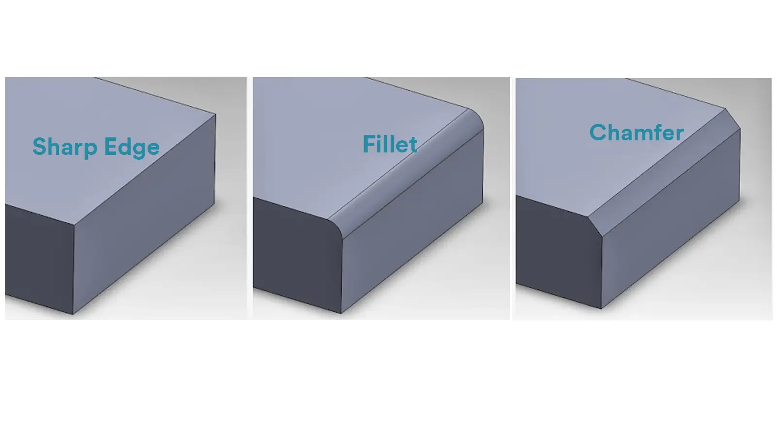
A fillet in CNC is a smooth, rounded transition applied to the corner or edge where two surfaces meet. A chamfer is a beveled edge that replaces a sharp 90° corner with a sloped surface, usually at a 45° angle.

China is the best country for CNC machining service considering cost, precision, logistic and other factors. Statistical data suggests that China emerges as the premier destination for CNC machining.

Selecting the right prototype manufacturing supplier in China is a critical decision that can significantly impact the success of your product development project.

Machining tolerances stand for the precision of manufacturing processes and products. The lower the values of machining tolerances are, the higher the accuracy level would be.