Updated: December 05, 2023
Generally, the surface quality of parts produced by CNC machining is good enough for most applications. However, some surfaces require additional finishing processes such as polishing. These operations can significantly increase production costs.
There are several ways to improve the quality of the finished part, Such as increasing the speed, reducing the feed, and so on.
In this post, you will learn how to measure the surface quality for CNC machined parts and tips about improving the surface finish in the CNC machining process.
Surface roughness is the shorter frequency of real surfaces relative to the thoughts. It’s quantified by the deviations in the direction of the normal vector. In this case, the ideal form of the finished surface is the referential value.
The logic is simple — if the deviations are large, the surface is rough. And vice versa, the lower the value of deviation, the finer the surface finish is. The parameter has a huge impact on wear resistance, motion accuracy, service life, and more.
Take a look at what the surface roughness is in the image below.
The measure of surface finish is Ra — average surface roughness. The deviation for the coarse surface of, for one, a cost iron is about 2,000 Ra. The ultra-smooth surface of the telescope’s mirror may be close to zero. The appropriate value is defined by the technical requirement for a particular part.
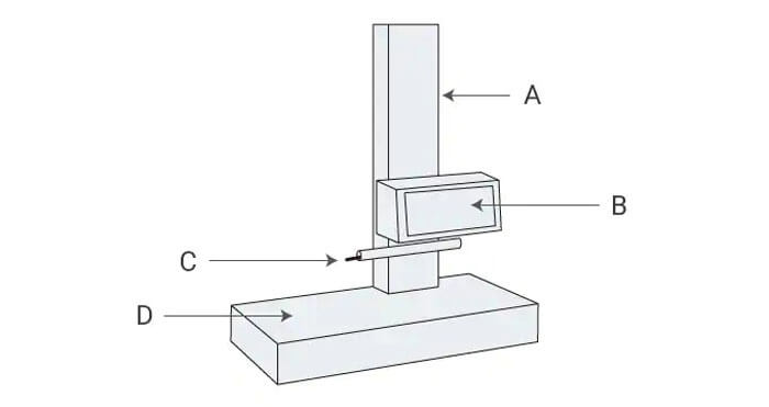
Roughness is measured by a surface roughness meter — an instrument that checks the smoothness of the surface. The main types of devices are probes or lasers. Some models measure both flat and curved surfaces.
Roughness meters trace the probe across the surface or emit a laser beam to detect the reflected light. The direction of the instrument is key. Typically, components that are measured perpendicularly show more reliable results. Measurements are repeated at gradually increasing speeds until there is no fluctuation in the measured values.
See what a surface measurement unit may look like in the image below.

Processes that affect surface quality are:
Now, let’s proceed with ways of improving the end surface condition. These are numerous yet should be given a good deal of thought to eliminate any risks to your best quality assurance.
Related Post: Difference Between Feed Rate and Cutting Speed in CNC Machining
Adjusting the mentioned above parameters is already one of the best tool recommendations. Here are some of the complementary advice.
As a rule, higher values of surface feet per minute (SFM) directly result in the reduction of built-up edge (BUE). It also prolongs tool life and reduces the risks of tool failure and damage to a component.
Just ensure that the coolant pressure is sufficient, raw material is not prone, and the tooling is appropriate.
Another rule is that a slower inch per revolution (IPR) or simply feed rate reduces flank wear and prolongs wiper insert life. It also helps to avoid poor finish outcomes and achieve a more accurate tool path.
When rouging, it’s especially vital to use a tool capable of high feeds, while when finishing, light depth of cut at high speeds works better. Although, you should be cautious about the phenomenon when the tool rub and not cut. Use the depth of cut of 0.0020 inches. It suits most applications.
Take angle is definite as a variable in the cutting tool insert’s design. Let’s take a 45-degree lead face mill as an example. If the cutting force acts downward with this tool, it; may cause a part to flex after the cutter passes over it.
On the contrary, a 90-degree cutter creates the parallel force and does not make it flex, resulting in better dimensional tolerances and an excellent finish. Play with both lead angle and the tool pressure to achieve the best outcomes.
Metal chips are the waste procedure in the process of machining. Tools are constructed in a way that helps chips evacuate. Yet, manufacturers experience problems with this waste on and off since it scratched the surface in the process.
Use a chip breaker to reduce cutting pressures and produce smaller or shorter chips that can be evacuated easily. Significantly, you deal with materials that produce long, stringy chips. A chip break will not let them interfere with high-end finishing.
See what chip breakers look like in the image below.
Every material is different, so choosing an appropriate chip breaker is not easy. Some options may work better for you, so give several of them a try.
Besides, pay attention to the setup stability, roughing application, and coolant usage. These factors combined together are what matters when choosing a chip breaker.
Besides, there is a direct dependency between the size of the insert’s nose radium and the type of surface finish produced. The interesting thing about this factor is that smaller nose radiuses decrease the pressure of tooling. Yet, they also limit the feed rate that can be set.
Any insert is capable of feeding only one-half of the nose radius. Basically, to avoid producing thread, you should use the largest radiuses possible. This would also eliminate chatter.
Another benefit of using a larger radius is a heavier cut that you can make. It’s useful when you have to process hard-to-cut materials. Such tooling is also less prone to wear.
Yet, larger nose radiuses take more materials from the workpiece. For example, using a 0.032-inch nose radius, you cannot finish there is only 0.01 inches to be removed.
Basically, using an insert with a wiper is the first piece of advice you may get from an experienced CNC mechanic. An insert with a wiper is capable of creating a much smoother surface in the milling pass.
It also makes it possible to increase feed rates without compromising the quality of the finished, as detailed in the above section. It qualifies when the speed of machining is crucial.
Besides, pay close attention to the tool diameter that you use. The cutter should be engaged somewhere between two-thirds and three-fourths of it for the best outcomes.
Unsurprisingly, the technique is crucial for achieving fine surface finishes. Thick-to-thin should be your very first rule to apply.
Arc-in and arc-out cutting ensures minimal impact on the insert edge due to the creation of a smooth transition. The same is for going into a corner.
Another piece of advice is to choose a cutter that is smaller than the radius. This way, you can program the cutter for the most smooth transition possible and eliminate sharp moves. This ensures the optimal tool path, deprived of deviations.
Well, some inserts may be used for routing, regular cutting, and finishing. You just change some parameters such as feed rate, speed, etc. Some manufacturers just utilize slightly used inserts for roughing.
Yet, it’s far not the most optimal way to get a smooth finish. Just because roughing should be done by using a large nose radius nose and a rapid feed rate. At the same time, the finishing tool with the desired angle should have a smaller nose, as described above.
Another vital consideration is the very material that inserts are made of. Cermet insert often produces better finishes, but it’s simply not applicable for heavy-duty roughing.
Remember, a light depth of cut should be equal to or more than the radius. Overview the tool will be just using the material forward.
Chip evacuation is a big deal, as you can see. It’s accompanied by a choice of whether or not to use coolant. Considerations here are the type of operation to perform, the material type, and the insert type.
You want to avoid applying coolant in milling operations and in turning applications involved with interrupted cuts.
On the contrary, with sticky materials such as aluminum or low-carbon steel, coolant will help you prevent material from sticking to the tool and, respectively, chips from not evacuating properly and damaging the surface.
When it comes to surface finishing, another overlooked factor is a tool holder itself. As an example, if the tool holder is old and it has a worn pocket, the insert may move. Fluctuations are minor, yet, they impact the end quality. Every uncontrolled movement results in a poor surface finish.
These fluctuations, called chatter, are caused by improper fixturing and tool holding. Another case is when a matching tool is not rigid, which is an essential problematic aspect.
Rigid workholding is also important. If both tooling and workpiece move uncontrollably, a good surface finish is absolutely cannot be achieved.

The first thing that specialists and users notice is the quality of the finish. Respectively, the reputation of every manufacturer is heavily based on the quality and consistency of the finishing process in place.
Basically, you have all good reasons to improve or not to let deteriorate your surface finish practices. To achieve this, pay attention to nose radius, chip evacuation, coolant, feed speed, rate and angle, the use of wiper, and a chip breaker, if necessary.