Updated: December 04, 2023
Today we are going to be talking about how to properly format a CAD file for CNC machining. This is an important step in the manufacturing process, as it ensures that your part will be cut accurately and efficiently.
In this post we’ll walk you through the process of setting up your file, and then discuss some specific tips for technical drawing. Let’s get started!
Start with preparing 2D or 3D designs of end components for CNC machining. Digital models perform the essential role — enabling engineers to visualize what shapes and forms a CNC machine should produce out of a workpiece.
Choose a CAD software to create your machinable design drawings — 2D or 3D files. Your options for producing them are the following:
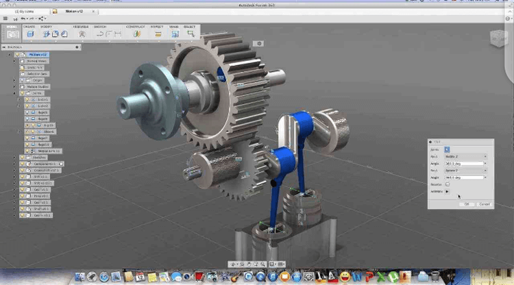
See what the finished designs of CAD models may look like in the image below.
Use such programs to convert 2D images (in PDF files) into 3D files. Or, as an alternative, to scan an image to form digital technical drawings out of it. You may create CAD drawings that would serve as blueprints as well.
But what are CAD files intended it for the semi-automated or manual creation of complex 3D technical drawings. Ones that have, for one, standard tolerances, types of material, and critical dimensions indicated. CAD programs naturally have sets of tools for creating forms and shapes for you to design any model your desire.
Once you have finished with your technical drawing, you may proceed with converting it to the CNC format.
CNC units like lathe or milling machines are incapable of reading CAD formats. In CNC machining, you always need to use a standalone CAM software or a CAM extension to a CAD program to transform a file with a digital model into a G-coded file type.
The latter is simply a text file in which all the operations that CNC machine units can perform are indicated. Examples are cutting operations such as moving a spindle along one or another axis or rotating a spindle (G-code). And there are indicated non-cutting operations such as start or stop, tool changing, coolant adding, etc. (M-code).
These coded commands, combined in one file, serve as instructions for a CNC machining unit. The latter performs every action specifically as per these commands to receive the repeatable, predictable result with each standardized workpiece.
Here are some of the fairly popular CAM programs:
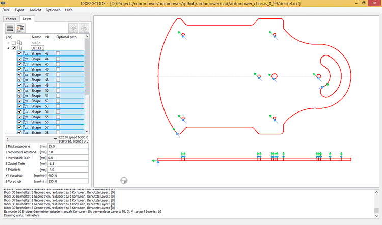
These programs automatically convert a CAD file into a CAM file. The latter can be in one of these formats: STEP, 3DM, DXF, IGES, DWG, and others (depending on the brand of the CNC machine supplier). To be exact, one of the end files in any of these formats it’s what engineers call CNC formats.
Take a look at what the CNC format file looks like in the image below.
An engineer may make manual adjustments to the finished files. Normally, a specialist has to fix mistakes raised from the automated conversion. It’s only the first circle of cleansing the mistakes of converting CAD files to CNC formats.
Now, you have a digital model in the form of a CAD file and a G-coded CAM file. Yet, both are rather for CNC programs than for engineers and machine operators. Humans need more traditional technical drawings to supervise CNC machining correctly. Think of those drawings as blueprints.
Here are some of the features that should be indicated in those technical drawings:
The idea behind such a drawing is to actually provide an engineer with a more traditional overview of a part for the machining. A CNC unit cannot read such files, but your employees can. They supervise your manufacturing lines, after all.
Staff use blueprints for inspecting machined parts, performing QA testing, indicating areas that must meet tight tolerances, and just for adjusting a CNC machining unit. Most adjustments to CNC files are made manually in this phase by labor.
Besides, the technical drawings must contain specific notes that cannot be conveyed in machine language. This concerns cross-sections for features that are not visible, materials, sizes of tooling, and many more.
See what such a drawing may look like in the image below.

After the challenges associated with preparing CAD and CAM files and blueprints are overcome, the time for sending the files has come. You should consider contacting a reliable CNC services provider to complete your project successfully.
Consider ECOREPRAP as your trusted manufacturer. We analyze the files you sent and generate a free quote quickly. We offer you superior customer support, fast turnaround time, close attention to your requirements, and the highest quality machining.
Once we start working on your files, our engineer team examines them and defines if there are any inaccuracies and if any other information is needed. We offer rapid prototyping services and CNC design assistance for you to receive a fully-fledged finished product that you keep in mind while submitting files to us.