What is CNC Face Milling?
Updated: December 06, 2023
Introduction
When you need to machine a perfectly flat surface, you typically have a number of options. One of them will necessarily be face milling. This popular manufacturing operation is a great addition to your scope of cutting processes.
So, let’s drive into the basics of face milling, review the required tooling, types of such operations, and how it is different from the peripheral CNC milling process.
1. What is CNC Face Milling?
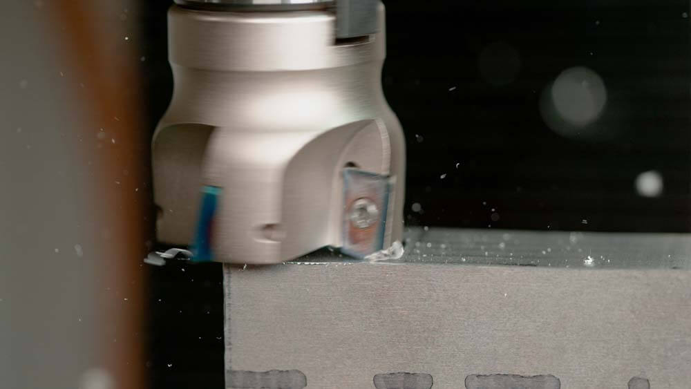
CNC face milling is a machining process in which a cutter is placed perpendicular to a workpiece – a “face down” position. When a mill is launched, the cutting edges remove material off the workpiece’s external surface.
Manufacturers use a rotating milling cutter to perform face milling. The working principle is moving a spindle in a horizontal direction from the outside of the stock. So, a cutter removes all the material at a specified depth.

2. Why is Face Milling Used?
Absolutely always, manufacturers need a workpiece to have a wide, flat, smooth surface that is suitable for performing other types of machining processes. In case face milling was omitted, the quality of, for example, drilling or taping would deteriorate significantly.
Another purpose of face milling is to eliminate an undesirable layer of material of a workpiece. It is a waste of metal rather than a functional operation but is performed regularly over unsatisfactory workpieces.
Finally, face milling may be used to simply separate or cut a workpiece into several sections or several smaller workpieces. There is specialized machinery for this purpose, but for example, rapid manufacturing allows machinists to show a certain degree of creativity.
3. What Types of Tools are Primarily Used to Perform Face Milling?
The selection of tooling for face milling is probably, the most interesting aspect of the entire process and has some nuances to consider. Let’s review common types of cutters and entering angles.
Types of Cutters
Here are the cutting tools you may choose from:
- End mill is a typically flat bottom, round, or radiused cutter that is much similar to a drill. It can cut axially, but from the perspective of face milling, it enables lateral cutting as well.
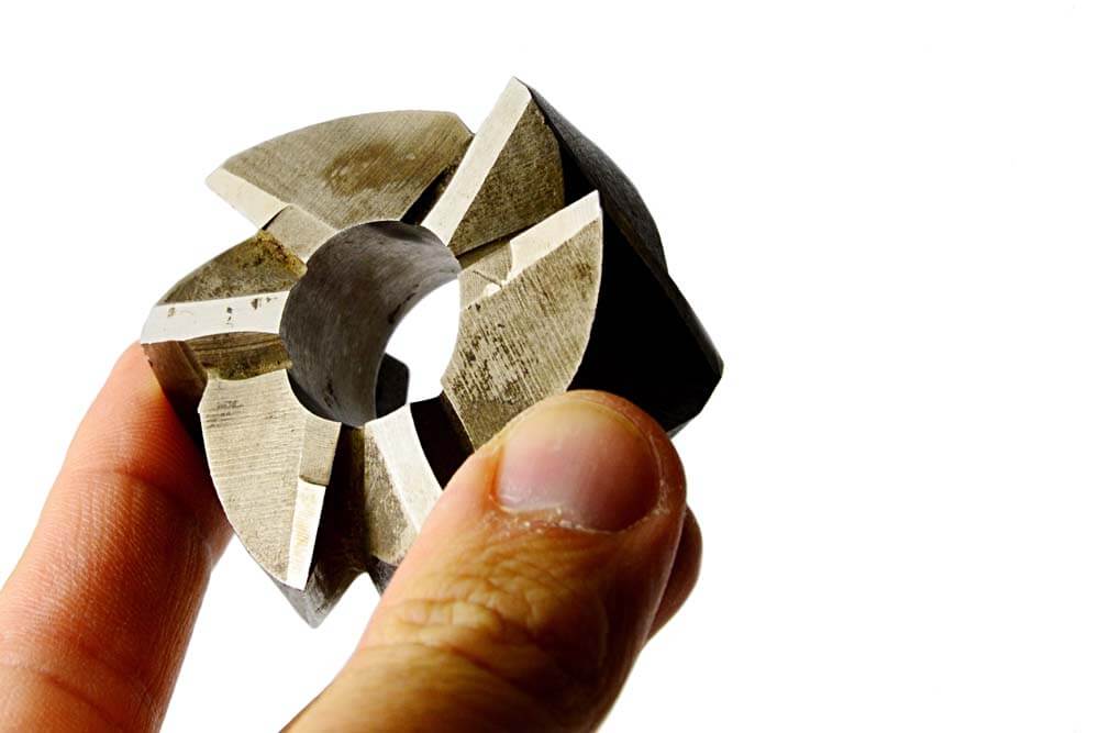
- Face/shell mill is conventional tooling that cannot cut axially but has cutting edges on its cutting head’ sides. These edges, or teeth, are replaceable inserts made of carbide.
- Ball cutter or ball mill is a tool with a hemispherical cutting tip. It performs perpendicular face cuttings due to maintaining a corner radius.
- Slab mill is a cutter that spins in a horizontal position between the spindle and the support while removing large amounts of material from a workpiece.
- Side-and-face cutter is an outdated version of the end mill. It has teeth around its circumference and enables performing highly effective but tough cuts.
- Fly cutter is an alternative to face mils. This cutter has a central body that holds together one or two tool bits. This type of toling is often DIY made for different purposes.
- Hollow mill is the opposite of the face mill, and it is being rotated while a workpiece is fed to it instead of vice versa. As a result, a cylindrical outcome is produced.
- Roughing end mill is the same end mill but with jagged teeth. It makes the process of cutting less precise but more effective. Another benefit of this tool is that metal chips are smaller than with a regular end mill, and they are easier to evaluate and clean off.
Among the mentioned tools, end mills, face mills, and fly cutters are used for face milling conventionally. Other types of tooling can be adapted to suit such purposes but only as complementary tooling.

Entering Angles
The second vital consideration after choosing a cutter is an entering angle, i.e., the angle between a leading cutting edge and the workpiece surface. It is also called a direction of cutting forces, and it majorly affects chip thickness and tooling life. You can see what cutters with different entering angles look like in the image below and the comparison of the angles in the table.
| 10° entering angle | 25-65° entering angles | 90° entering angle | |
|---|---|---|---|
| Advantages | High productivity High feed rate Favorable, for spindle stability, direction of axial cutting force | Optimal productivity Favorable for face milling Multi edge insert options Reduce vibrations and weak set-ups | The most versatile angle Favorable, for thin-walled components, the strength of axial forces Best for weak-fixture components |
| Disadvantages | Low depth of cut | Moderate depth of cut | Lower productivity |
| When to use | For intricate designs and large-sized batches of products | For medium-sized batches or when other two options are rather unsuitable | For small batches of products that changes frequently |
4. Types of Face Milling Operations
There are dozens of combinations of cutting tools and their entering angles, as detailed. But, only four milling operations can be distinguished:
- General face milling
It is a conventional process that is compatible with all the existing cutters and entering angles. Round insert and large radius cutters are used for this process. They are general-purpose cutters with strong cutting edges and are suitable for heat-resistant alloys, unlike other face milling operations on the list.
- High feed milling
When you machine aluminum and, for example, cast iron with ceramic inserts in your tooling, cutting speeds may reach as much as 1000 revolutions per minute. Such a case is considered an example of High-Speed Machining (HSM). Consequently, you can set a high feed rate to employ the increased efficiency fully. That’s what you may know as high feed milling.
Such a process requires using of a cutter with small entering angles, typically 10°, and round inserts. It will help to achieve a feed rate of as much as 4mm/tooth. Needless to mention that the depth of such a cut is limited to 2.8 mm only, but the feed rate makes the entire operation take seconds of time instead of minutes. So, in certain circumstances, you may achieve extremely high productivity.
- Heavy-duty face milling
It is rather a rough face milling process. It is typically applied to material blanks, castings, and welded structures. For heavy-duty milling, manufacturers use powerful machines that can withstand the increased stresses.
Since large amounts of materials are removed in the process, a large amount of energy is generated by high cutting forces. Consequently, both pressure and temperature applied to a cutter are high. It is essential to operate at full depth of cut to reduce the risk of tooling failing. So, not every cutter will suit heavy-duty milling.
10° and 90° entering angles deteriorate rapidly during the process. So, tooling with a 60° entering angle is optimal. It provides good cut capacity depth while not compromising the feed rate. Besides, the axial allowance of such cutters allows a parallel land that benefits the quality of face milling.
- Finishing with wiper inserts
This method provides the highest quality finishes. From a certain perspective, it is a general face milling with a standard insert in combination with one or more wiper inserts. The latter perform ideally at higher feed rates per revolution.
So, finishing with wiper inserts is a great way to modify your conventional milling. It increases the feed by 2-3 times without compromising quality. It also helps to achieve a “mirror finish.”
5. How to Choose the Right Face Milling Operation?
Since there are multiple options to combine particular tools and face milling operations, you may need some explanations on how to choose one. Here are some factors to pay attention to while making a decision:
- Workload. Some types of face milling operations, like finishing with wiper inserts, suit the manufacturing of large batches of products better. It is correct only when the milling operations go with a combination of proper cutters. General face milling is an ideal option for mixes of small batches of components.
- Your particular intent. For example, to remove large amounts of material rapidly and roughly or achieve the highest precision possible. Guide your choice accordingly.
- Type of workpieces. In case you ordered castings, be prepared to apply for heavy-duty milling first. But if you have already prepared components, you can go with bare general face milling.
- Design of a workpiece. It is highly inadvisable to mill over pre-drilled holes, for example. But the consistency of high feed machining consistency over the surface will severely deteriorate if applied to such a component. Heavy duty and general face milling are less demanding in this aspect.
- Design of a finished component and technical requirements. It is frequent that you cannot achieve high precision by using, for example, heavy-duty or high feed milling. So be sure the chosen method meets the requirements set to the finished component’s design. Also, thin-walled components can be produced only by means of general face milling or finishing with wiper inserts (ineffective).
- Material of a workpiece. Consider that high-feed milling can be performed over the thick sheets of durable metals by appropriate tooling. So, if you are unsure that a workpiece will withstand increased temperature and pressure, better go with general milling or finishing with wiper inserts.

You can decide on the choice of a face milling process alone. But do not forget to select an appropriate cutter with a sufficient entering angle as well as per the characteristics above.
6. Face vs Peripheral Milling What’s the Difference?
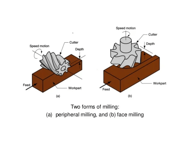
Peripheral milling is another machining process that can produce wide, flat surfaces. Unlike face milling, it requires a parallel tool positioning to grind material away at the top of a workpiece’s surface. The main difference is that peripheral milling engages the sides of a cutter rather than just its tip. So, peripheral milling is more effective for heavy-duty types of work due to a deeper level of material removal.
Here is a comparison of the face and peripheral milling based on several factors:
| Factor | Face milling | Peripheral milling |
|---|---|---|
| Placing of a cutter | cutter is positioned perpendicular to a workpiece | cutter is positioned parallel to a workpiece |
| Versatility | Superior, with the support of intricate designs | Moderate, as extremely limited in creation of designs |
| Productivity | Moderate to high level of efficiency | Superior level of efficiency |
| Precision | Can achieve a superior level of accuracy in some processes | Is rather a rough process, but still offers a good smoothness of flat surfaces made |
| Suitability for heavy-duty machining | Suitable enough | Extremely suitable |
| Suitability for machining thin-walled components | Suitable | Cannot be used for this purpose in the vast majority of cases |
| Compatible milling machines | Both horizontal and vertical spindle centers | Horizontal spindle centers only |
The point here is that these operations can hardly replace each other. So, you most likely will need to apply both procedures. Take a look at what they may look like in the image below.

7. Summary
You should go for face milling anytime you need a flat surface for making further manufacturing operations over workpieces. Such machining is considered one of the simplest ones but still offers multiple combinations of tooling and processes to choose from.
Pay attention to the workpieces that you machine, the intended design, and the required productivity. This way, you will find a best-fit face milling process and a cutter to your needs.