
1. What is CNC Machining?
CNC machining is a subtractive manufacturing process that involves using computer-controlled machines to shape, cut, and carve materials into precise components or parts. It stands for “Computer Numerical Control.”
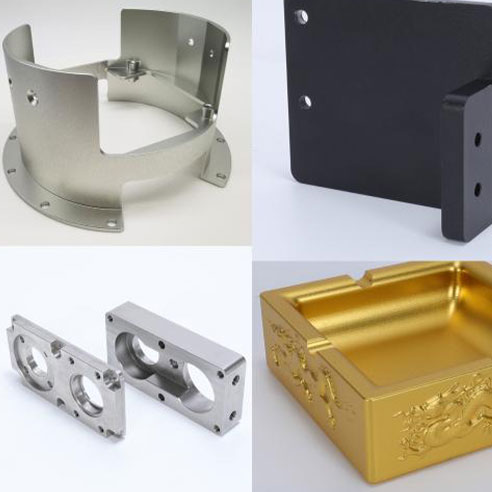

CNC Machining Metals CNC Machining Plastics
CNC machines can work with a wide range of materials, including metals, plastics, woods, and composites.There are some key advantages of CNC machining, including precision, repeatability, complex geometry and efficiency.
1.2 Types of CNC Machines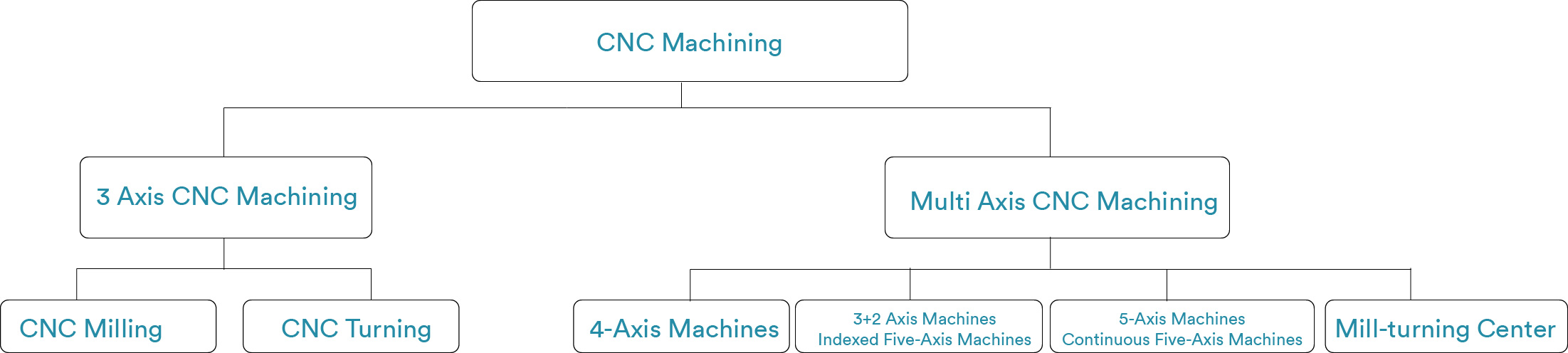
1.2.1 CNC Milling Machines:
CNC milling machines are versatile tools that use rotating cutting tools to remove material from a workpiece. They are perfect for 2D and 3D machining.Common applications include creating slots, holes, and complex geometries. Milling machines come in various configurations, such as vertical and horizontal mills.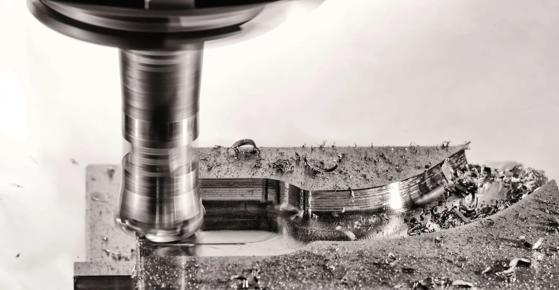
1.2.2 CNC Lathe Machines:
CNC lathe machines are designed for turning operations. They spin the workpiece while a cutting tool removes material to create cylindrical shapes.
Lathe machines are commonly used for producing shafts, pins, and other cylindrical components.
Variations of lathe machines include standard lathes, Swiss-style lathes, and multi-axis lathes for complex work.
1.2.3 Multi-Axis Machines
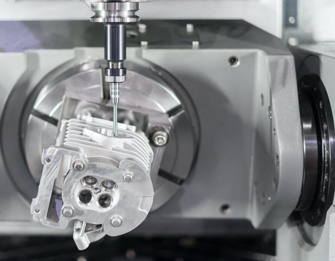
Multi-axis machining refers to CNC machines with more than the standard three axes (X, Y, Z). These machines often have additional rotational or tilting axes.Benefits of multi-axis machining include the ability to produce complex parts with fewer setups, reduced tool changes, and improved surface finishes.Applications for multi-axis machining include aerospace components, medical implants, and intricate molds for the automotive industry.
3+2 Axis Machines(Indexed Five-Axis Machines): These machines have three primary linear axes (X, Y, Z) and two additional rotary axes. The tool can be positioned at various angles, providing access to different sides of the workpiece. This is often used for complex part positioning.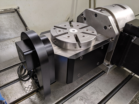
4-Axis Machines: In 4-axis machining, there are four primary axes (X, Y, Z) and an additional rotary axis, usually designated as the A-axis. This allows the workpiece to rotate around a specific axis, enabling more complex and precise operations.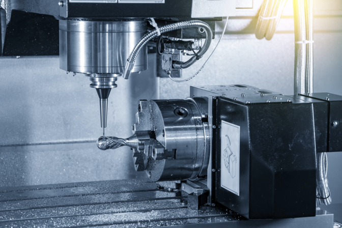
Mill-turn machine: The turning and milling processes in machining, is also known as turn-mill or mill-turn machining. This is a machining technique that combines the functions of a lathe (turning) and a milling machine (milling), allowing operators to perform both rotational and linear cutting operations on the same machine tool. In turn-mill machining, the workpiece is usually clamped on a rotating spindle, and then cutting is performed using tools or milling cutters. This technology enables various cutting operations to be executed on a single machine table, reducing the need for workpiece reclamping and repositioning.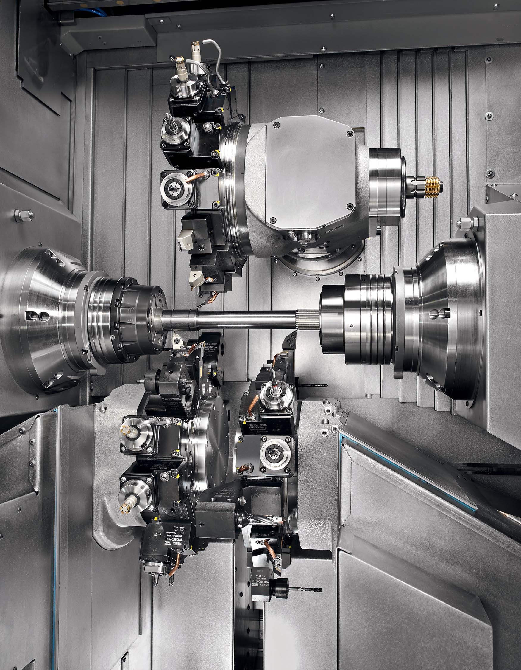
2. Basics of CNC Machining
2.1 CNC Machine Components
2.1.1 The Workpiece:
The workpiece is the raw material that will be machined. It can be a metal bar, plastic sheet, wooden block, or any other material suitable for the application.Proper selection and preparation of the workpiece are essential for successful machining.
2.1.2 The CNC Controller:
The CNC controller serves as the central intelligence of the CNC machine. It interprets the G-Code program and sends signals to the machine’s motors to control its movements.It manages toolpath planning, speed and feed settings, and safety functions.
2.1.3 The Cutting Tool:
Cutting tools are responsible for material removal. They come in various shapes, including end mills, drills, and inserts.Tool selection depends on the material being machined and the desired geometry of the part.
2.1.4 The Workholding Device:
The workholding device securely holds the workpiece in place during machining to prevent movement or vibrations.Common workholding methods include clamps, vises, chucks, and custom fixtures, depending on the part’s size and shape.
2.2 How CNC Machines Work
2.2.1 CAD/CAM Software:
CAD (Computer-Aided Design) software is used for designing parts in 2D or 3D. It allows engineers and designers to create a digital model of the part.CAM (Computer-Aided Manufacturing) software takes the CAD design and generates toolpaths. It considers factors like tool selection, toolpath optimization, feeds and speeds, and tool changes.
2.2.2 G-Code Programming:
G-Code is the language CNC machines understand. It consists of commands that instruct the machine on tool movements, spindle speed, tool changes, and other operations.G-Code is generated either manually by experienced operators or through CAM software.
2.2.3 CNC Machine Movement:
CNC machines have multiple axes (commonly X, Y, and Z) that can move the cutting tool in various directions.The G-Code program dictates the tool’s movements, controlling its path, depth, and speed during machining.
3. Material Selection
3.1.1 Metals:
Metals are a popular choice for CNC machining due to their durability and strength.
Common metals used in CNC machining include aluminum, steel, brass, copper, titanium, and stainless steel.Each metal has unique properties. Check all the materials ECOREPRAP provides for CNC machining.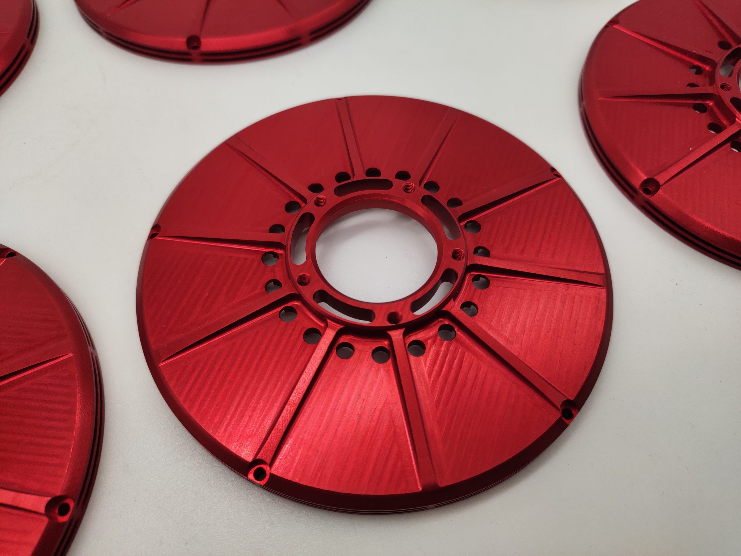
CNC Aluminum Parts
3.1.2 Plastics:
Plastics offer versatility and are often chosen for their lightweight and corrosion-resistant properties.Common plastics used in CNC machining include ABS, acrylic, polyethylene, and PEEK.
Different plastics have varying levels of hardness and thermal stability, making them suitable for specific applications.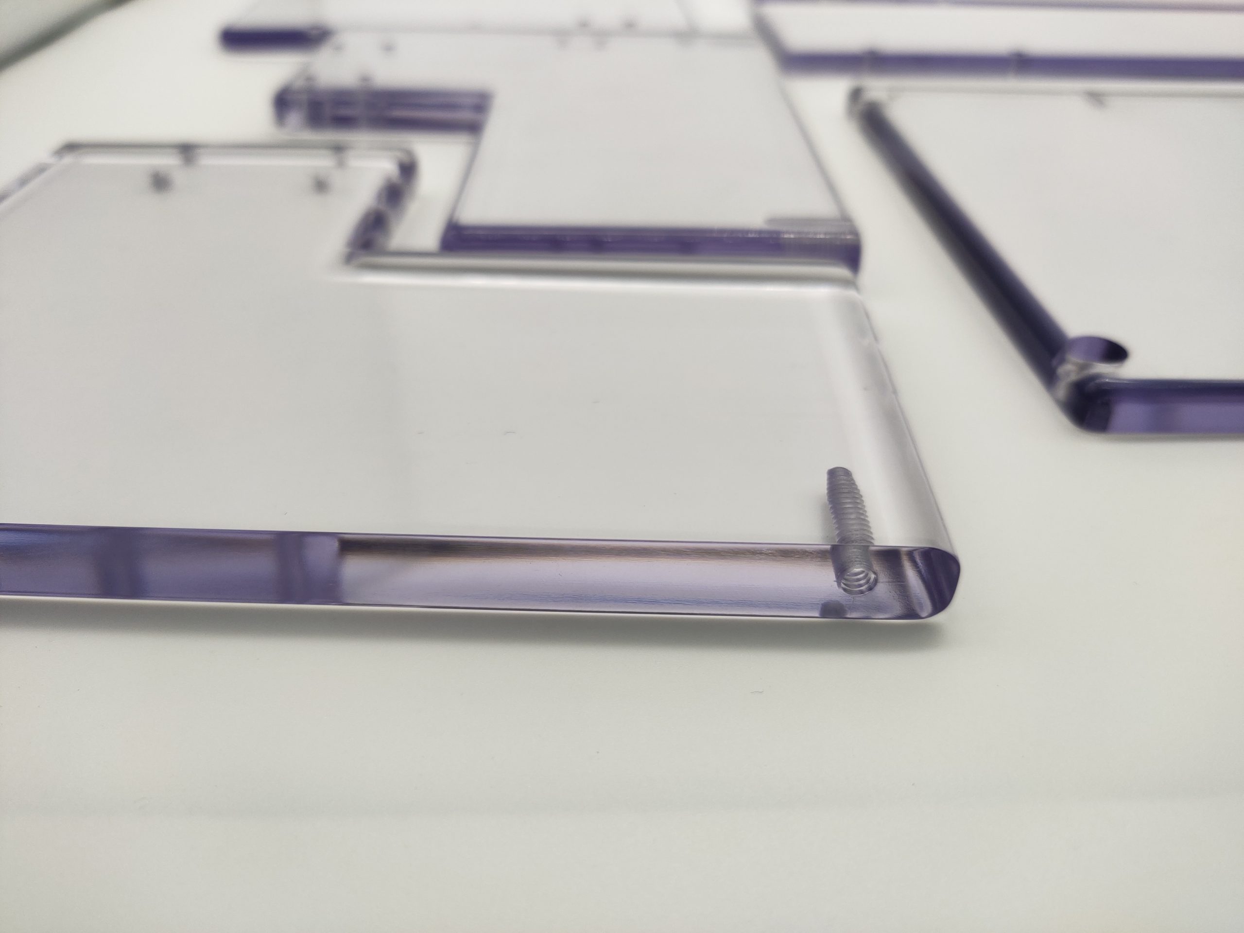
3.1.3 Woods:
Woods are favored for decorative and artistic CNC machining projects.Woods like oak, maple, and plywood can be carved and routed with precision.Each wood type has its own grain patterns and hardness, affecting the machining process and finished appearance.
3.1.4 Composite Materials:
Composite materials combine different substances to create materials with unique properties.
Carbon fiber composites, for example, are used in aerospace and automotive applications due to their strength-to-weight ratio.CNC machining of composites requires specialized tools and expertise to avoid delamination or damage.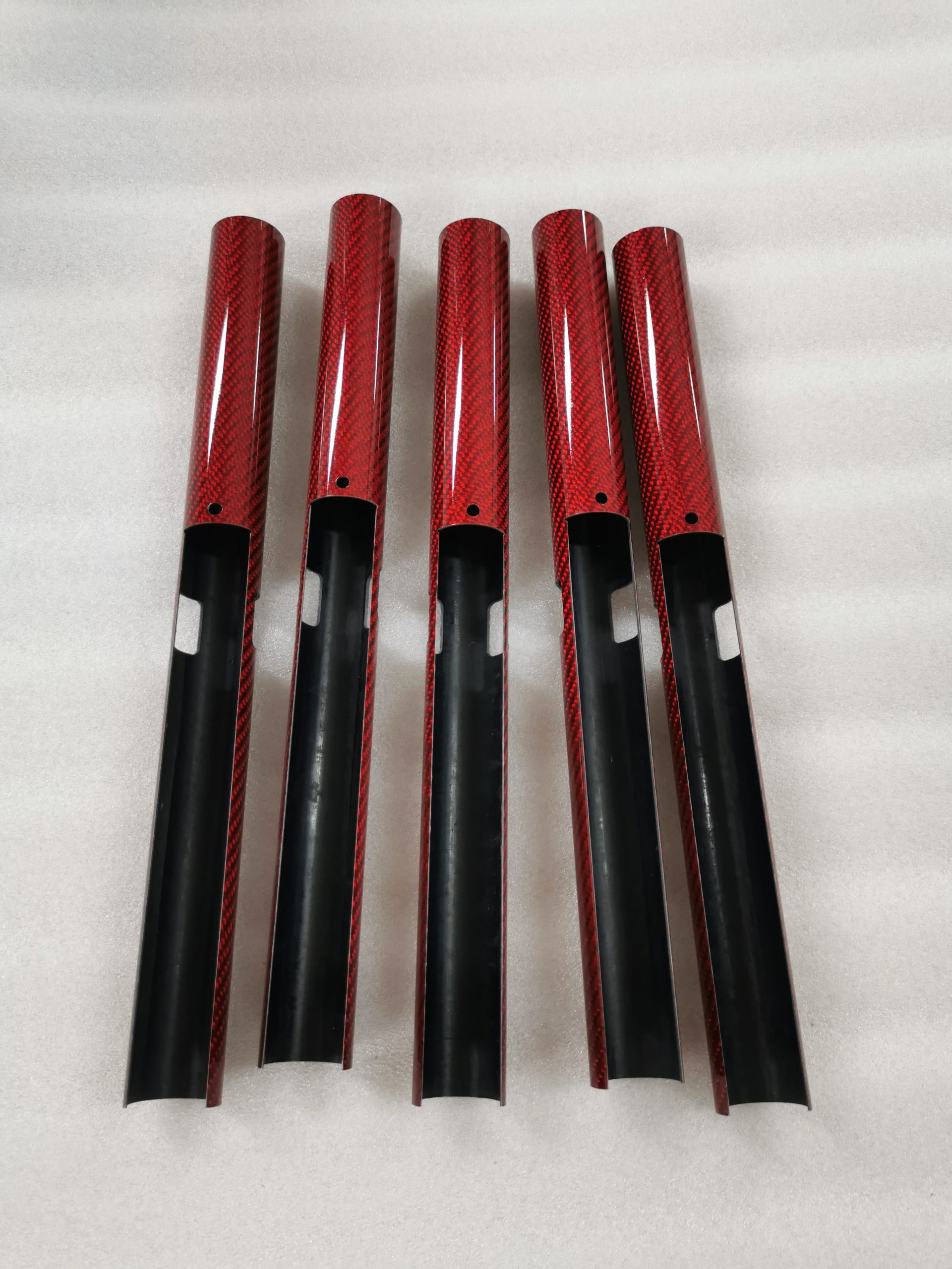
3.2 Tool Selection
3.2.1 Types of Cutting Tools:
Cutting tools come in various types to suit different materials and applications.
End mills are versatile tools used for many machining tasks, while drills are ideal for creating holes.Ball end mills are used for contouring, and chamfer mills create beveled edges.Specialized tools like reamers and countersinks serve specific purposes.
3.2.2 Coatings and Materials:
Tool coatings enhance tool durability and performance. Common coatings include TiN (Titanium Nitride), TiAlN (Titanium Aluminum Nitride), and DLC (Diamond-Like Carbon).Tool materials range from high-speed steel (HSS) to carbide. Carbide tools are more wear-resistant and suitable for high-speed machining.
3.2.3 Toolholders and Collets:
Toolholders secure cutting tools in the machine’s spindle.Collets grip the tools with precision and are used to accommodate different tool shank diameters.Proper selection of toolholders and collets is critical to ensure tool stability during machining.
4. CNC Programming
4.1 Introduction to CAD/CAM Software
4.1.1 CAD for Design:
CAD (Computer-Aided Design) software is a fundamental tool for CNC machining.
CAD software allows engineers and designers to create detailed 2D or 3D digital models of the part to be machined.Designers can precisely define the part’s shape, dimensions, and features using CAD software.CAD software often includes features for drawing, dimensioning, and creating geometric entities, making it a powerful tool for generating the digital representation of the part.
4.1.2 CAM for Manufacturing:
CAM (Computer-Aided Manufacturing) software complements CAD and is critical for CNC machining.CAM software takes the digital design created in CAD and translates it into a set of toolpaths that the CNC machine will follow to create the physical part.CAM software considers various factors such as tool selection, toolpath optimization, feeds and speeds, and tool changes.
It generates a CNC program (usually in G-Code) that guides the machine during the manufacturing process.
4.2 Writing and Understanding G-Code
4.2.1 G-Code Fundamentals:
G-Code is the language that CNC machines understand. It consists of a series of commands that direct the machine’s movements, toolpath, and operations.
Common G-Code commands include:
G00: Rapid positioning command for fast, non-cutting movements.
G01: Linear movement command for cutting or traversing between points.
G02/G03: Circular interpolation commands used for creating curves and arcs.
M03/M05: Spindle control commands to start or stop the spindle.
Operators or CAM software generate G-Code based on the CAD design and toolpath specifications.
4.2.2 Creating CNC Programs:
Creating CNC programs involves translating the toolpath instructions generated by CAM software into a sequence of G-Code commands.The CNC programmer or operator needs to consider factors like tool changes, tool offsets, work coordinate systems, and safety protocols.
CNC programs are typically loaded onto the CNC machine’s control unit for execution.
4.3 Simulation and Verification
4.3.1 Virtual Machining:
CAM software often includes simulation tools that allow users to visualize the machining process before it’s executed on the physical machine.
Virtual machining simulations provide insights into how the tool interacts with the workpiece, uncovering potential issues like tool collisions, over-travel, or inefficiencies.
This step helps avoid costly mistakes and optimize the machining process.
4.3.2 Debugging G-Code:
Debugging G-Code involves carefully reviewing the code to identify errors or potential issues.
Operators and programmers look for syntax errors, missing commands, incorrect tool settings, and logical inconsistencies.Debugging ensures that the CNC program runs smoothly and produces the desired part.Effective CNC programming is a crucial aspect of CNC machining, as it bridges the gap between the digital design and the physical part. CAD, CAM, and G-Code play integral roles in achieving precise and efficient machining results.
5. Setting Up the CNC Machine
5.1 Material Preparation
5.1.1 Material Dimensions:
Accurate measurement and specification of the material dimensions are fundamental in CNC machining.Precisely knowing the length, width, and thickness of the workpiece is crucial for setting up the CNC machine and planning toolpaths. Accurate material dimensions ensure that the CNC program operates as expected, preventing potential collisions and misalignment.
5.1.2 Material Fixturing:
Material fixturing is the process of securely holding the workpiece in place on the CNC machine table to prevent movement during machining.
Various methods are used for fixturing, including clamps, vises, custom fixtures, and vacuum tables.Proper fixturing is essential for maintaining workpiece stability and ensuring the accuracy of machining operations.
5.2 Tool Setup and Offsetting
5.2.1 Tool Length Offsets:
Tool length offsets are used to determine the precise distance from the tool tip to a reference point, typically the machine’s work surface.Accurate tool length offsets are vital for avoiding collisions and achieving consistent machining results.
CNC machines often have tool-length measurement probes to automatically set tool length offsets.
5.2.2 Tool Diameter Offsets:
Tool diameter offsets are critical for CNC machines to understand the exact size of the tool, including its radius.These offsets ensure that the tool follows the intended toolpath and maintains the desired part dimensions. Setting tool diameter offsets is typically done using a reference tool or manual measurements.
5.3 Work Coordinate Systems
5.3.1 Machine Zero and Part Zero:
Machine zero, also known as the machine reference point, is the fixed reference position defined by the machine manufacturer.Part zero, also known as the work offset, is the point on the workpiece where the CNC program considers as the starting reference.Accurate alignment between machine zero and part zero ensures that the CNC machine starts and operates in the correct position.
5.3.2 WCS Setup:
Work Coordinate Systems (WCS) are defined coordinate systems within the CNC machine’s software.WCS allows operators to establish part zero and align the workpiece with machine zero using the machine’s controller.Accurate WCS setup ensures that the CNC machine knows where to start machining and how to interpret the toolpath.Proper setup in CNC machining is the foundation for successful and precise manufacturing. Accurate material preparation, tool setup, offsets, and WCS configuration are essential to achieve consistent and high-quality results.
6.1 Machine Startup and Homing
6.1.1 Powering On:
The first step in running a CNC machine is powering it on. This involves turning on the machine’s control unit, which initializes the system.Safety checks, including emergency stops and door interlocks, should be functioning properly before starting the machine.
6.1.2 Homing Sequence:
Once the machine is powered on, it often goes through a homing sequence. During homing, the machine’s axes move to predefined reference positions.
This sequence helps establish known starting points for each axis and is essential for accurate machining.
6.2 Running a CNC Program
6.2.1 Loading the Program:
Loading a CNC program onto the machine’s control unit is the next step. The program is typically stored on a connected computer, USB drive, or network.The operator selects the desired program from the storage location and loads it into the machine’s memory.
6.2.2 Setting Feeds and Speeds:
Once the program is loaded, the operator configures the machine’s feed rates (how fast the tool moves) and spindle speeds (the tool’s rotational speed). These settings are based on factors like material, tool type, and machining requirements.
6.3 Monitoring and Adjustments
6.3.1 Real-time Monitoring:
During the CNC machining process, operators and CNC programmers often engage in real-time monitoring.They observe the machine’s operation, watching for any unexpected behavior or potential issues.Real-time monitoring might involve checking tool engagement, chip evacuation, and coolant flow.
6.3.2 Overrides and Corrections:
To ensure that the CNC machine produces accurate parts, operators can make adjustments in real-time.Overrides allow operators to adjust feed rates and spindle speeds on the fly, either to optimize the process or correct errors.Corrections might involve modifying the toolpath, making tool changes, or addressing unexpected issues like tool wear.
Running a CNC machine is a dynamic process that involves careful monitoring and management of various parameters. Ensuring the machine’s proper startup, homing, program loading, and real-time adjustments is essential for achieving precise and efficient machining results.
7. Post-Processing and Quality Control
7.1 Inspecting the Finished Part
7.1.1 Dimensional Accuracy:
Dimensional accuracy is a critical aspect of quality control in CNC machining. After a part is machined, it’s essential to check its dimensions against the design specifications.
Inspection tools such as micrometers, calipers, and coordinate measuring machines (CMMs) are used to measure the part’s features.
If there are deviations from the intended dimensions, adjustments or corrections may be required.
7.1.2 Surface Finish:
Surface finish refers to the quality of the part’s outer surface. Achieving the desired surface finish is essential, especially for parts that will interact with other components or for aesthetics.
Surface roughness is typically measured in Ra (average roughness) or Rz (maximum roughness). Measurement tools such as profilometers are used to assess surface finish.
Post-processing steps like sanding, polishing, or coating may be required to meet surface finish specifications.
7.2 Deburring and Surface Finishing
7.2.1 Deburring Techniques:
Deburring is the process of removing sharp edges, burrs, and unwanted material from the machined part. Various deburring techniques are used, including manual deburring using files or abrasive pads, automated deburring using machines, or chemical deburring processes.
Deburring ensures that the part is safe to handle and free from potential sharp edges that can cause injury.
7.2.2 Surface Finishing Options:
Surface finishing involves enhancing the appearance and functionality of the part’s surface.
Options for surface finishing include painting, anodizing, electroplating, powder coating, and more. ECOREPRAP provides 20 plus surface finishes.Surface finishes can provide corrosion resistance, improved appearance, or special properties like electrical conductivity. Check all the 20 plus surface finishes ECOREPRAP provide.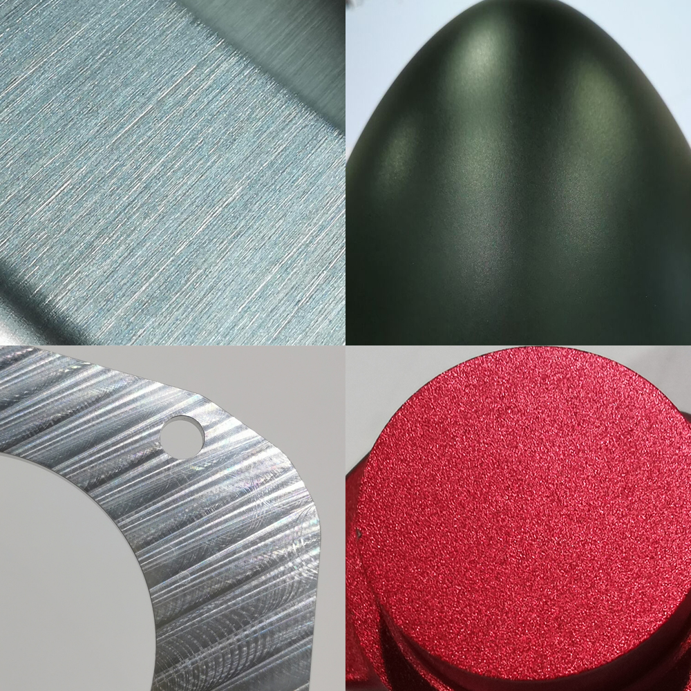
7.3 Part Marking and Identification
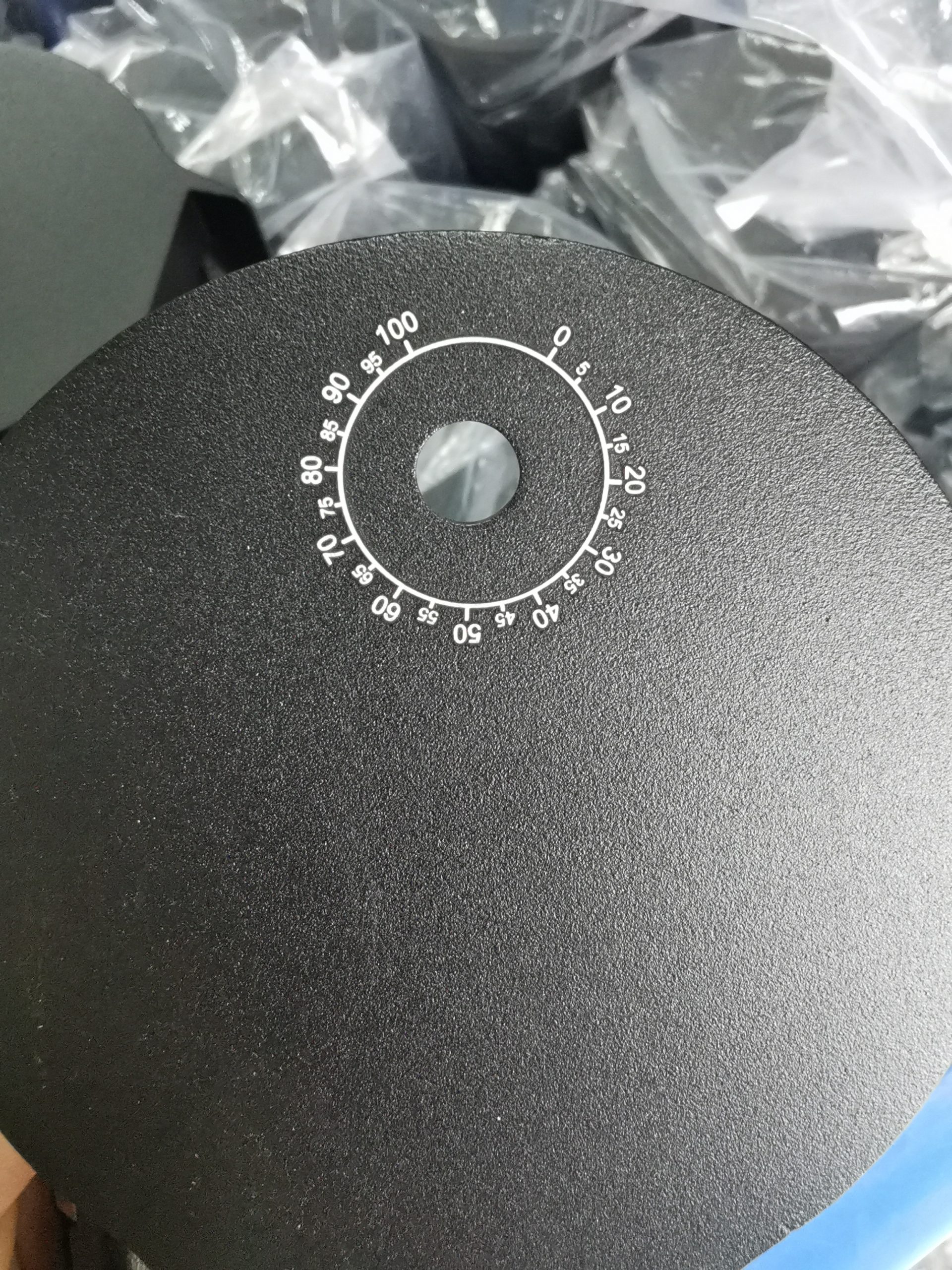
7.3.1 Engraving and Marking Methods:
Part marking and identification are essential for traceability and quality control.
Engraving methods include laser engraving, mechanical engraving, or chemical etching.
Parts may be marked with serial numbers, part numbers, logos, or other identification details.
7.3.2 Serialization and Identification:
Serialization involves assigning unique serial numbers to parts, allowing for easy tracking and identification.Serialization helps with inventory control, traceability, and quality assurance.It is crucial in industries such as aerospace, automotive, and medical devices.
Post-processing and quality control are integral parts of CNC machining. Ensuring the finished part meets design specifications, has the desired surface finish, is free from sharp edges, and is properly marked for identification are key aspects of delivering high-quality components.
8. Troubleshooting and Maintenance
8.1 Common CNC Machine Issues
8.1.1 Tool Breakage:
Tool breakage is a common issue in CNC machining and can result from various factors such as excessive cutting forces, improper tool selection, or poor tool maintenance.
Operators must monitor tool wear, use appropriate cutting speeds and feeds, and ensure tools are correctly installed to prevent breakage.
When tool breakage occurs, it can lead to costly downtime and potential damage to the workpiece.
8.1.2 Chip Problems:
Chips produced during machining can cause problems, including chip jamming, coolant blockages, and poor surface finishes.Managing chip evacuation is essential, and this can involve using appropriate chip removal equipment, adjusting toolpath strategies, and optimizing coolant flow.
Proper chip management contributes to efficient machining and minimizes disruptions.
8.1.3 Program Errors:
Program errors can arise due to issues in the G-Code, incorrect toolpath generation, or operator mistakes.Operators should review G-Code for accuracy and syntax errors. CAD/CAM software should generate correct toolpaths.Regular training and documentation can help minimize programming errors and prevent costly mistakes.
8.2 Preventive Maintenance
8.2.1 Lubrication:
Lubrication is crucial for maintaining the health of a CNC machine. Effective lubrication minimizes friction, safeguards against wear, and guarantees seamless functionality.CNC machines have various lubrication points that need regular attention, including ball screws, guides, and spindle bearings.Following the manufacturer’s recommendations for lubricants and maintenance intervals is essential.
8.2.2 Calibration:
Calibration ensures that the CNC machine operates accurately. It involves verifying and adjusting the machine’s components, such as linear guides and encoders.Regular calibration prevents errors and inaccuracies in machining and maintains dimensional precision.Calibrating critical components may require specialized equipment and expertise.
8.2.3 Periodic Inspections:
Periodic inspections are necessary to detect wear, misalignment, or other issues early.Inspection routines involve examining critical components, checking for loose fasteners, and verifying the condition of wear parts like belts and pulleys.Scheduling and conducting regular inspections can help prevent breakdowns and extend the machine’s lifespan.
9. Safety and Best Practices
9.1 CNC Machine Safety:
CNC machine safety is paramount to protect both operators and the equipment.Key safety measures include using personal protective equipment (PPE), installing machine guards, and implementing emergency procedures.Operators should receive training on safe machine operation and follow established safety protocols.
9.2 Best Practices:
Implementing best practices in CNC machining ensures efficiency and quality.Factors like workholding considerations, efficient toolpath strategies, and sustainable machining techniques are critical.Optimizing toolpath planning, minimizing tool changes, and selecting appropriate machining strategies help improve productivity.
Maintaining and troubleshooting CNC machines, while also adhering to safety and best practices, are essential for smooth and efficient operations. Preventive maintenance can extend machine lifespan and reduce downtime, while safety measures and best practices ensure a safe and productive working environment.
Chapter 9: Safety and Best Practices
9.1 CNC Machine Safety
9.1.1 Personal Protective Equipment:
Personal Protective Equipment (PPE) is crucial to safeguard CNC machine operators from potential hazards.Common PPE includes safety glasses, hearing protection, gloves, and appropriate clothing. The specific PPE required depends on the machine and materials used.
PPE helps protect against debris, coolant splashes, and noise-related issues.
9.1.2 Machine Guards:
Machine guards are physical barriers or enclosures designed to shield operators from moving machine parts and flying chips.They prevent accidental contact with rotating spindles, cutting tools, and other hazardous components.Proper machine guarding is a legal requirement in many industrial settings to ensure operator safety.
9.1.3 Emergency Procedures:
Establishing clear emergency procedures is essential for CNC machine safety.Operators should be trained on how to respond to emergencies like tool breakage, power failures, or fires.Emergency stop buttons and safety interlocks are commonly used to quickly halt machine operations in case of an issue.
9.2 Best Practices
9.2.1 Workholding Considerations:
Proper workholding is essential for the safety of both operators and the quality of machining.
Workholding devices should securely grip the workpiece to prevent movement, reducing the risk of accidents.Considerations like part size, shape, and material influence workholding methods, which can include vises, clamps, vacuum tables, or custom fixtures.
9.2.2 Efficient Toolpath Strategies:
Efficient toolpath planning can reduce machining time, tool wear, and energy consumption.
Techniques such as optimizing feed rates, minimizing toolpath air moves, and reducing rapid traverses contribute to sustainable and cost-effective machining.CAM software can automatically generate toolpaths that optimize machining efficiency.
9.2.3 Sustainable Machining:
Sustainable machining practices aim to minimize the environmental impact of CNC machining.
Reducing waste, optimizing tool usage, and recycling coolant are sustainable strategies.
Selecting eco-friendly cutting fluids and responsibly disposing of waste materials contribute to environmentally responsible manufacturing.
Ensuring CNC machine safety through PPE, machine guards, and emergency procedures is essential to protect the well-being of operators. Implementing best practices, including workholding considerations, efficient toolpath strategies, and sustainable machining, enhances productivity while reducing environmental impact and costs.
10. Future Trends and Conclusion
10.1 Industry 4.0 and Automation:
Industry 4.0 represents the fourth industrial revolution and involves the integration of digital technologies into manufacturing processes. In CNC machining, this translates to the adoption of smart factories and automation.CNC machines can be equipped with sensors and connected to the Internet of Things for real-time monitoring and data collection.
Automation in CNC machining includes the use of robotic arms for loading and unloading parts, as well as automated tool changing systems. These advancements improve efficiency, reduce downtime, and enable predictive maintenance to prevent breakdowns.
10.2 Conclusion and Resources:
In conclusion, CNC machining is a versatile and indispensable manufacturing technology with applications spanning various industries.
This comprehensive guide has provided insights into the basics of CNC machining, materials and tooling, programming, machine setup, operation, quality control, troubleshooting, maintenance, safety, and advanced techniques.
The future of CNC machining is marked by increasing automation, connectivity, and data-driven decision-making. Industry 4.0 is transforming the landscape of manufacturing, and CNC machining plays a vital role in this technological revolution. By embracing these trends, CNC machining will continue to be a cornerstone of modern manufacturing, offering precision, efficiency, and versatility in the production of a wide range of components and products