- Capabilities
-

CNC Machining
Tight tolerance and 20+ finishes 3, 4 , 5 axis, as fast as 2 days -

Sheet Metal Fabrication
High-precision, on-demand sheet metal cutting and bending. -
3D Printing
SLA, SLS,MJF,SLM, FDM 3d printing with post treatment. -

Vacuum Casting
Production quality parts without the tooling investment.
-
- Solutions

Rapid Prototyping
Fastest lead time of high-quality prototypes at minimal cost.

Low Volume Production
From one-off prototyping to low-volume production.

Mechanical Assembly
Custom assembly for project-specific needs.

Custom Package
Ready to help you prompt your brand.
- Sources

Materials
Select from 100 more types of metals and plastics.

Finishes
Select from 20 more types of surface fishes.

Industries
Providing precision machining and manufacturing solutions.

Cases
How we assist our clients in bringing their projects to fruition.
- Company

Quality Assurance
Consistent quality, every time.

About Us
Your go-to manufacturer for custom parts.

Newsroom
Learn updated news about ECOREPRAP.
Types of Toolpaths strategies for Optimize CNC Machining
Updated: December 03, 2023
Introduction
Optimizing CNC machining involves a range of factors and requires increasingly specialist knowledge. You can optimize your machining rate, improve surface quality, reduce tool wear and improve your quality of outcomes to achieve the highest professional standards. Techniques for optimization of tool path dramatically affect the productivity that can be achieved.
The programmers target is to generate an optimized tool path that removes feed challenges by various strategies. For example, achieving near net shape in the roughing process requires machine software that has awareness of changes in surface topology that happen between step-downs. The best machining addresses this between-the-layers stage, reducing the extent of semi-finish passes to reduce machine time.
In this post, we will explain several types of toolpath strategies about optimize CNC machining. You can learn this methods to improve the part quality and reduce the machining cost.
1. Face
The Face toolpath is the most basic approach and it is generally used for lowering large flat areas to prepare for detail extraction that follows. As a rule, this type of cutter vector is a simple zig-zag with cutting in both directions and tight, slower turns at the direction reversal points.
One common use is to rough a face of an uneven stock material, to provide a flat surface to sit onto the work table. The characteristic straight crossbars/ tangential end radius pattern can often be seen on resulting parts
2. Constant Stepover
This is perhaps the most basic and commonly used default pocketing toolpath strategy – so much so that in some systems it is not even given a name. It involves a toolpath in which the cutter follows the net-shape of a machining pocket, using parallel paths, separated by the constant stepover that the name suggests.
This is a very consistent and uniform toolpath strategy that results in regular cutter marks, but it involves an excessive number of turns and resultant slowdowns, so it is far from optimal in machine time, limiting productivity because of excessive corner loading influence. TrueMill is one of several strategies that overcome this limitation.
3. Pencil Milling
Pencil milling is the final stage toolpath for machining tight internal radii, using small diameter and often ball ended tools to machine residual material, as a last stage process. It is used in areas that are inaccessible with the larger tools that allow fast material removal. Named pencil milling for the way it follows radii like it’s drawing tham, it’s often referred to as the ’rolling ball’ toolpath.
Constant step-over path elements are often applied to pencil milling to create parallel pencil milling passes for the finish-cutting of corners and fillets.
In particular, pencil milling allows a cutter tool path and cutter selection where the feature to be cut is the same diameter as the cutter.
4. Contour
As the name suggests, this toolpath follows the contour of a part, either external or pocket/internal, in a series of 2D cuts that are not directly connected, but involve a move to a new path and a plunge cut to the next lower level.
Contours can be open or closed, for example in following one corner of an upstand, there is no closed path. However, since contour cuts make slots, only one side of an endmill is generally cutting. To avoid excessive tool deflection, because of this, the depth of cut and feed rate must be reduced.
5. Horizontal Machining
Horizontal machining can refer to the tool axis of rotation lying on the horizontal plane, so cutters generally protrude horizontally away from the machine and cut across the workpiece, rather than being oriented axially downwards. This results in specialist considerations in cutter path, although mounting the work side facing can essentially revert the function of the setup to the more common vertical axis in all major regards.
This setup has advantages such as easier integration of automation in toolchagers; considerably better chip flow, as gravity carries the chips away, rather than into the cutter pocket; and better utilization of spindle time. But it requires a shift in mindset in the operator/programmer.
Horizontal machining is also a cutter path strategy for a vertical axis cutter setup, whereby all the horizontal surfaces are cut as a group, generally first, to be followed by other strategies for curved and sloped surfaces.
6. Rest Machining or Rest Roughing
This toolpath system allows roughing processes with a large diameter tool to be completed as a first stage, before a tool change to a smaller tool is made to complete the cuts that require this. By this means, the passes of the larger tool are ‘rested’ and returned to with the required secondary cutter. The name also originates from programming needing to keep track of the ‘rest of the material’ to be removed.
The main advantage of this approach is that it reduces the number of toolchanges by aggregating work blocks for each tool, in essentially disconnected paths that will be connected by the secondary operation, generally with a smaller diameter tool.
7. Chamfer
Chamfer toolpaths are used to create flat and curved simple surfaces, either by angling a parallel cutter (on a multi axis machine) or by switching to an angled cutter.
The orientation of the spindle to achieve the angle requires fewer tool changes and allows unlimited angles to be used, as well as transitions between angles. It also imposes limitations because of the tip angle of the cutter (90° generally).
Use of an angled cutter requires more toolchanges but can reduce the tip restrictions in operation and ease the programming process by removing an axis of complication. Chamfer angles being set by the cutter, transitions are not possible and angle options are restricted.
8. Fillet
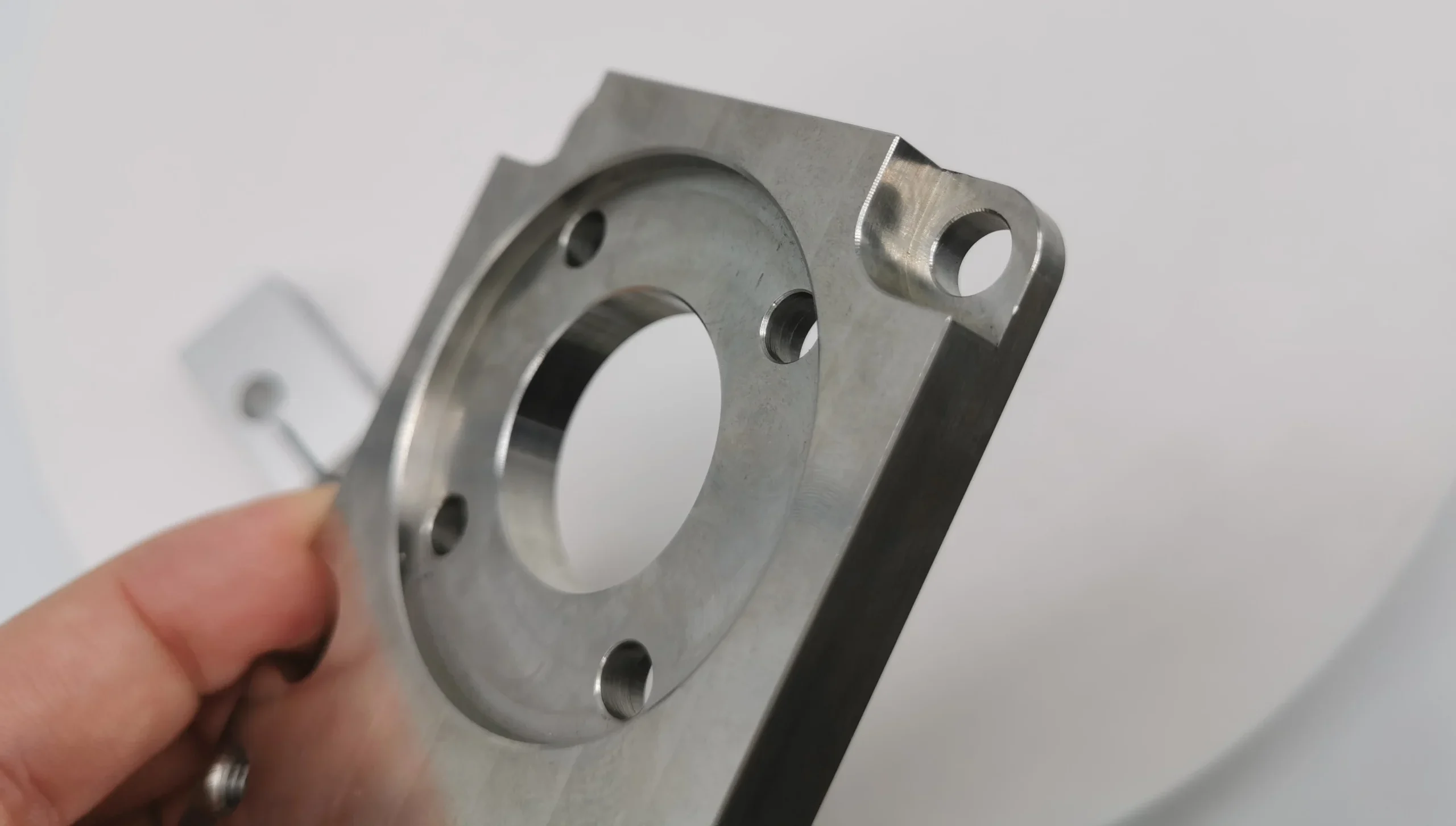
The filleting of toolpaths blends straight feeds together using smooth curves. This avoids the sudden stops of sharp corners and allows the maintenance of faster feed rates, overall. It also improves surface quality by removing the scuffing circles and cutter edge burnish lines that result from the stopped feed at the corners.
Virtually no aspect of cutter path definition has a greater impact on overall feed rates than the slowdown and stop cycle that automatically results from approaching a sharp corner. Obviating this wastage is a very valuable way to improve overall production efficiency, and filleting the tool path is among the most effective tools for this.
Related Post: Chamfer vs Fillet: What’s the difference?
9. Zig-zag Clearing
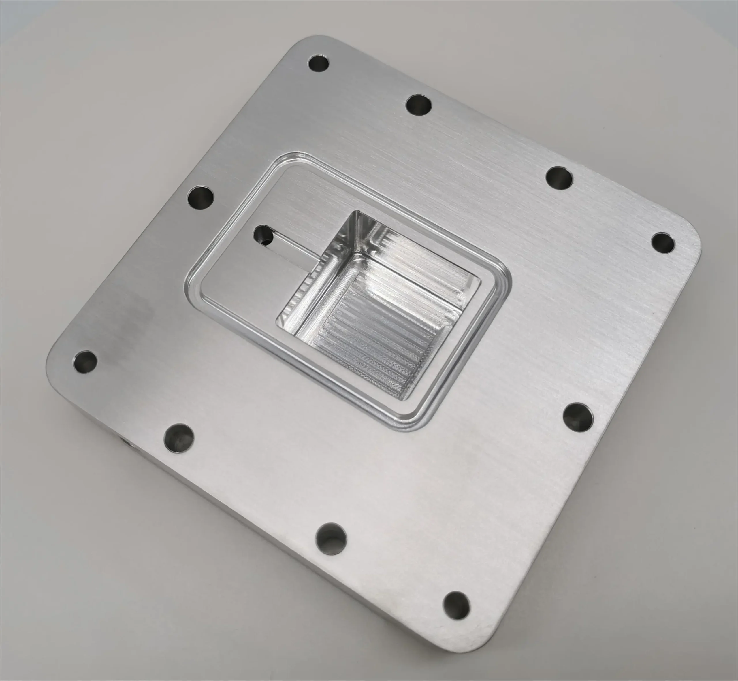
Zig-Zag clearing maximizes the use of straight line movement in the cutter path, and it’s widely employed in cutting sculptured and complex 3D surfaces. In operation, the tool zig zags back and forth over the workpiece, with the z-level varying as needed.
Zig-zag clearing can achieve better overall cutting rates than more basic tool path strategies, in particular when comparing with flatter toolpaths use a single direction of cut and traverse back to a start point to make the next cutter pass. However, this strategy can result in poor and irregular surface finish and shorter tool life.
10. Spiral
Spiral tool paths are the subject of current research and developing quickly. Essentially they approximate the form of an upstand or pocket and cut a single continuous path by following a shrinking or expanding contour and constantly varying the Z height to achieve a one-path result.
The mathematics of the approach to generating the spiral, the degree of stepover (overlapping of paths) and the nature and restrictions in approaches to curvature are all variables that are under development. Some approaches are even tending towards the NURBS and point cloud view if surface definition, to produce adaptive cutter paths for the machining of intricate sculptured surfaces.
11. 3D Plunge Roughing
Plunge Roughing and more recently 3D plunge roughing delivers roughing by cutting in only the Z direction – as if repeatedly drilling holes to a precise depth that comes close to the net-shape sought. This allows generally higher cut rates in roughing, because most CNC machines are considerably more rigid in the Z direction, allowing greater forces to be applied and the use of larger cutters.
This tends to result in complex roughed surfaces which need care in the finishing or finer roughing stages, as forces on the cutter can alter significantly as major steps are encountered at points that can cause cutter problems.
3D Plunge roughing is at its most effective when the cutter is subject to climb milling.
12. Advanced Z Level Finishing
This method is suited to operations for pre-finishing or finishing. The cutter essentially follows contour paths in 2D, i.e. fixed Z planes, stepping down/up between cuts. It is best suited to parts made primarily of steep walls, operating ball mills to achieve smooth transition results in fewer cutter passes.
The cutter can either maintain a climb milling mode, or a conventional mode, or alternate between the two as conditions suggest. This is another cutter path strategy that is the subject of fundamental research and optimization. This paper presents the effect of varying part parameters such as surface gradient, tool end radius and cutting methodologies such as direction and depth of cut, feed rate per cutter edge on surface finish and more.
13. Pocket
Pocket milling is a cutter path that commences with a plunge cut, usually to the shallower of required cut depths, and then either contour, spiral or zig-zag milling to remove all cuttable material from a pocket at the plunged depth. This is followed by a stepover or traverse to the next zig-zag or contour pattern start point and a repeat of the smaller, next level roughing cut.
Despite offering the opportunity for the roughing cut to be the final cut on vertical and horizontal surfaces, best practice dictates leaving material for a finishing cut, to avoid major disjoints in surface finish.
14. Slot Mill
Slot milling uses only side or face milling operations by the cutter. Cutting operations start from the side of the workpiece or the open side of an already cut cavity or contour. The X, (or Y or combined feed in a vertical axis machine) then runs the side of the cutter into the workpiece and proceeds on a single, cutter width course to cut a straight, simply curved or contoured path through the material.
Slots come in all shapes and sizes – and where they do not coincide with a tool size available, a second pass that is not strictly a slot milling pass will be required to produce the final slot width. Machine type and volume/length of slot inform cutter selection which can be end mill, edge cutter or slot cutter. Of these, slot cutters offer the highest cut rates, especially when used on a horizontal axis machine. For vertical axis machines, this option is possible but less practical as it requires more setup in the tool change. For this reason end mills are a more practical choice.
15. True Mill
True Mill is a proprietary technique limited to SurfCAM equipment, although most other manufacturers have their own interpretation of the approach – for example Volumill and Adaptive Clearing. These are all examples of what are collectively known as Constant Tool Engagement angle HSM toolpaths or CTA. This is an adaptive approach that varies the stepover distance dynamically as cutters approach sharp corners, with the intent of limiting the TEA to maintain higher and less interrupted feed rates.
This approach delivers high throughput, as the tool path has the cutter working close to its limits at all points, resulting in shorter machining time and increased tool life by reducing cutter stress. It is a development of the more primitive and now rarely used trochoidal path approach.
TrueMill cut parts appear strange and almost random to those not familiar with the approach, which can make a surface finish that is interpreted wrongly as imperfect and disorderly.
16. Conclusion
Nothing about cutter path selection is as simple as it seems, but with an advanced understanding of programming and tool choices, dramatic improvements in throughput, tool life, surface finish and profitability can be achieved, so it is a valuable area of study, for the professional and the home/hobby user.
It should be noted that this is a primer, not a complete review resource. There is more to study and more to put into action than can be covered in a short introduction. However, this article covers the basics and shows the directions the reader can follow to achieve deep expertise.


