[et_pb_section fb_built=”1″ _builder_version=”4.16″ _module_preset=”default” background_image=”http://ecoreprap.com/wp-content/uploads/2022/02/machining-tolerance.jpg” custom_margin=”-61px|||||” custom_padding=”100px||161px|||” global_colors_info=”{}”][et_pb_row _builder_version=”4.16″ _module_preset=”default” background_color=”rgba(0,0,0,0.44)” global_colors_info=”{}”][et_pb_column type=”4_4″ _builder_version=”4.16″ _module_preset=”default” global_colors_info=”{}”][et_pb_text _builder_version=”4.19.4″ _module_preset=”default” header_text_color=”#FFFFFF” header_font_size=”45px” custom_margin=”||7px|||” hover_enabled=”0″ global_colors_info=”{}” sticky_enabled=”0″]

CNC Machining Tolerances, the Complete Guide in 2023

[/et_pb_text][et_pb_post_title title=”off” categories=”off” comments=”off” featured_image=”off” _builder_version=”4.16″ _module_preset=”default” meta_font=”Lato||||||||” meta_text_align=”center” meta_text_color=”#FFFFFF” meta_font_size=”17px” global_colors_info=”{}”][/et_pb_post_title][/et_pb_column][/et_pb_row][/et_pb_section][et_pb_section fb_built=”1″ _builder_version=”4.16″ _module_preset=”default” custom_padding=”4px||29px|||” global_colors_info=”{}”][et_pb_row column_structure=”2_3,1_3″ _builder_version=”4.16″ _module_preset=”default” global_colors_info=”{}”][et_pb_column type=”2_3″ _builder_version=”4.16″ _module_preset=”default” custom_padding=”|5px||5px|false|false” global_colors_info=”{}”][et_pb_text _builder_version=”4.16″ _module_preset=”default” text_font=”Lato||||||||” text_text_color=”#292929″ text_font_size=”17px” custom_margin=”||17px|||” global_colors_info=”{}”]Picture this: you are an expert in CNC machining tolerances, and can hand-pick the most appropriate accuracy for any machining process and any material. Sounds much like a superhero power, doesn’t it?

To grant you such proficiency, we created a detailed guide for CNC machining tolerances. It covers everything from the basic definition of machining tolerances to descriptions of their common types. As a bonus, we outlined useful recommendations for choosing appropriate tolerances.[/et_pb_text][et_pb_text _builder_version=”4.16″ _module_preset=”default” text_font=”Lato||||||||” text_text_color=”#292929″ text_font_size=”17px” custom_margin=”||15px|||” global_colors_info=”{}”]

What is Meant by Tolerance in CNC Machining?

[/et_pb_text][et_pb_text _builder_version=”4.16″ _module_preset=”default” text_font=”Lato||||||||” text_text_color=”#292929″ text_font_size=”17px” custom_margin=”||15px|||” global_colors_info=”{}”]

How the Concept of Tolerance has Emerged from CNC Machining

[/et_pb_text][et_pb_text _builder_version=”4.16″ _module_preset=”default” text_font=”Lato||||||||” text_text_color=”#292929″ text_font_size=”17px” custom_margin=”||21px|||” global_colors_info=”{}”]

For starters, CNC machining is referred to as a process of manufacturing a part of a raw workpiece. It is done by automated equipment units, cutting tools of which follow the programmed path. It is how a particular shape or a design can be obtained.

Unfortunately, as none of the human beings can avoid mistakes, none of the CNC centers can operate with 100% accuracy all the time. It leads to the necessity to consider a certain degree of error as an appropriate one and just operate with it further.

[/et_pb_text][et_pb_text _builder_version=”4.16″ _module_preset=”default” text_font=”Lato||||||||” text_text_color=”#292929″ text_font_size=”17px” custom_margin=”||14px|||” global_colors_info=”{}”]

The Definition of CNC Machining Tolerances and Related Subconcepts

[/et_pb_text][et_pb_text _builder_version=”4.16″ _module_preset=”default” text_font=”Lato||||||||” text_text_color=”#292929″ text_font_size=”17px” custom_margin=”||21px|||” global_colors_info=”{}”]So, let’s get down to business. Machining tolerance is also well-known for dimensional accuracy. It is basically the amount of permitted variance in dimensions of a component crafted. In other words, it is how significantly a CNC machine is allowed to be mistaken. 

There always is a particular range within which a certain value of accuracy is acceptable. You may have heard of this range as a distance between a maximum and minimum dimensional limit for a distinct type of component. In quality assurance, these limits are known as admissibility criteria or acceptance criteria. 

There is also a concept of sub-quality products. In the context of CNC machining, it is any finished product the dimensions of which exceeds the criteria of acceptance.[/et_pb_text][et_pb_text _builder_version=”4.16″ _module_preset=”default” text_font=”Lato||||||||” text_text_color=”#292929″ text_font_size=”17px” custom_margin=”||14px|||” global_colors_info=”{}”]

The Way CNC Machining Tolerances Work in Real-life

[/et_pb_text][et_pb_text _builder_version=”4.16″ _module_preset=”default” text_font=”Lato||||||||” text_text_color=”#292929″ text_font_size=”17px” custom_margin=”||21px|||” global_colors_info=”{}”]Here’s how it goes: a manufacturer requires a hole in a part with a diameter of 45 mm. The given acceptance criteria are ±0.5 mm. Therefore, any part with a hole’s diameter that falls in the range between 44.5 mm. and 45.5 mm. is considered acceptable quality. In case a hole’s diameter has gone beyond the range, the part is considered sub-quality.

The range of acceptance detailed above is also referred to as the ‘tolerance band.’ The rule of thumb is the larger the difference between the maximum and minimum dimension limits, the looser the tolerance band, and vice versa.

While a manufacturer may have its own acceptance criteria for a part’s dimensions, a CNC machine unit always has a particular level of accuracy. A supplier cannot guarantee that its automated center will consistently produce parts with required dimensions if the requirements to these criteria are exceeded. It is so because a machining center is simply not designed for it.

The simple truth is that if a CNC machine unit’s tolerance, claimed by a supplier, is tighter than the acceptance criteria to a component, there is no problem at all. However, you will definitely need a new automated machine if a component should be manufactured with precision, a center is not designed for.[/et_pb_text][et_pb_text _builder_version=”4.16″ _module_preset=”default” text_font=”Lato||||||||” text_text_color=”#292929″ text_font_size=”17px” custom_margin=”||14px|||” global_colors_info=”{}”]

Why are Tolerances Important in CNC Machining?

[/et_pb_text][et_pb_text _builder_version=”4.16″ _module_preset=”default” text_font=”Lato||||||||” text_text_color=”#292929″ text_font_size=”17px” custom_margin=”||21px|||” global_colors_info=”{}”]We devoted the entire above section to create an initial understanding of how principles of machining tolerances emerged. Now you’re ready for a few examples that show the particular importance of tolerances in CNC manufacturing.

Picture this. You have bought a new phone. An exceptional and expensive one. You’d definitely want this precious piece of electronics to be protected from falls, fingerprints, and scratches. For this purpose, you have ordered a premium phone case, which was delivered to you in no time. And when you try to fit your new device in your even newer phone case, there are basically two scenarios.

The good one is when both phone and the case are completely compatible with each other and suit perfectly. You can see how tightly your phone is positioned inside the case, and all the cutouts have the same contours as your phone’s camera and fingerprint scanner. You are happy with your purchase due to the great precision this case had been manufactured with.

In the worst-case scenario, everything works the other way around. Your phone is way bigger or smaller than its case, and just cannot be well-positioned inside it. Your device’s camera and fingerprint scanner are partially blocked by cutouts placed inappropriately. And all that sort of stuff. 

Phone cases are not that essential. But imagine we are talking about microelectronics, aircraft components, or surgery tools. As you can see, it is always better when appropriate tolerances are chosen.[/et_pb_text][et_pb_text _builder_version=”4.16″ _module_preset=”default” text_font=”Lato||||||||” text_text_color=”#292929″ text_font_size=”17px” custom_margin=”||14px|||” global_colors_info=”{}”]

Common Types of Tolerances in CNC Machining

[/et_pb_text][et_pb_text _builder_version=”4.16″ _module_preset=”default” text_font=”Lato||||||||” text_text_color=”#292929″ text_font_size=”17px” custom_margin=”||21px|||” global_colors_info=”{}”]The next point to discuss is common types of tolerances in computer-controlled machining. Their understanding is vital not to be confused when someone’s beginning to speak about acceptance criteria and tolerance bands in a manner you are not used to.[/et_pb_text][et_pb_text _builder_version=”4.16″ _module_preset=”default” text_font=”Lato||||||||” text_text_color=”#292929″ text_font_size=”17px” custom_margin=”||14px|||” global_colors_info=”{}”]

1. Standard Tolerances

[/et_pb_text][et_pb_text _builder_version=”4.16″ _module_preset=”default” text_font=”Lato||||||||” text_text_color=”#292929″ text_font_size=”17px” custom_margin=”||21px|||” global_colors_info=”{}”]

Standard tolerance is also referred to as engineering tolerance. It is a variation with which an equipment unit can operate in a broad sense. In CNC machining, it is an error in a workpiece’s dimensions.

An International Tolerance grade provides a general classification of CNC machines, or their tooling, by the tolerance they are designed for. Here is the list of tolerances that can define the grade of a CNC machine (equipped with cutting tools or without).

  1. ±0.2″ or ± 5,08 mm.
  2. ±0.01″ or 0,254 mm.
  3. ±0.005″ or 0,127 mm.
  4. ±0.0005″ or 0,0127 mm.

As such, a supplier may claim that its automated machine has an accuracy of 0.1 mm. It is a typical variance, most CNC machine types, such as mills, lathes, etc., operate with. As you can observe, 0.1 mm. suits grade 3, based on the scale detailed above.

Specifications regarding the basis of tolerances, deviations, and fits, are detailed in the normative international guide called ISO 286-1:2010

Alternatively, you may use the scale detailed below that considers machine variances and the linear dimension. Linear dimension range is basically referred to as the dimensions of a part being machined.

[/et_pb_text][et_pb_image src=”http://ecoreprap.com/wp-content/uploads/2022/02/ISO-2768-1.jpg” alt=”ISO-2768-1″ title_text=”ISO-2768-1″ align=”center” _builder_version=”4.16″ _module_preset=”default” custom_margin=”||19px|||” global_colors_info=”{}”][/et_pb_image][et_pb_text _builder_version=”4.16″ _module_preset=”default” text_font=”Lato||||||||” text_text_color=”#292929″ text_font_size=”17px” custom_margin=”||21px|||” global_colors_info=”{}”]You should not take such classifications as modes while negotiating with a supplier. But, based on the above-provided grades, you can see some of the standard tolerances. It is useful for purchasing new equipment units. [/et_pb_text][et_pb_text _builder_version=”4.16″ _module_preset=”default” text_font=”Lato||||||||” text_text_color=”#292929″ text_font_size=”17px” custom_margin=”||11px|||” global_colors_info=”{}”]

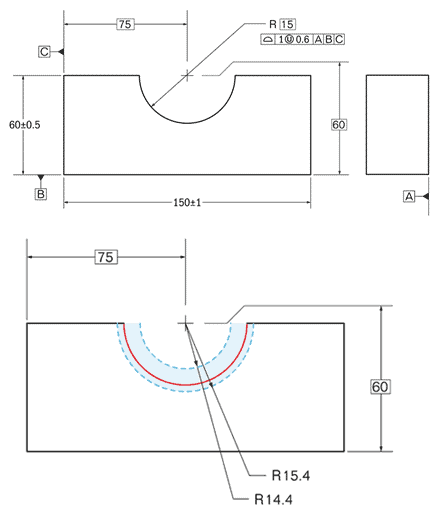
2. Bilateral Tolerances

[/et_pb_text][et_pb_text _builder_version=”4.16″ _module_preset=”default” text_font=”Lato||||||||” text_text_color=”#292929″ text_font_size=”17px” custom_margin=”||21px|||” global_colors_info=”{}”]This one is simple. Bilateral tolerance is the zone formed by equal distribution of the acceptable variance in both dimensions. In other words, it is the permitted error or deviance, which can be accepted regardless of the direction in which the error occurred. You can see the way it works in the infographics below.[/et_pb_text][et_pb_image src=”http://ecoreprap.com/wp-content/uploads/2022/02/Bilateral-Circularity-Tolerance.png” alt=”Bilateral-Circularity-Tolerance” title_text=”Bilateral-Circularity-Tolerance” align=”center” _builder_version=”4.16″ _module_preset=”default” global_colors_info=”{}”][/et_pb_image][et_pb_text _builder_version=”4.16″ _module_preset=”default” text_font=”Lato||||||||” text_text_color=”#292929″ text_font_size=”17px” custom_margin=”||21px|||” global_colors_info=”{}”]In the basic example, the manufacturer may give a workpiece to cut a hole. Dimension of the hole, i.e., diameter, is, for instance, equal to 30 mm. Criteria of acceptance is 0.1 mm. It means that according to bilateral tolerances, any diameters between 29.95 and 30.05 are acceptable.

The crucial point is that upper and lower limits are distributed from given dimensions equally.[/et_pb_text][et_pb_text _builder_version=”4.16″ _module_preset=”default” text_font=”Lato||||||||” text_text_color=”#292929″ text_font_size=”17px” custom_margin=”||11px|||” global_colors_info=”{}”]

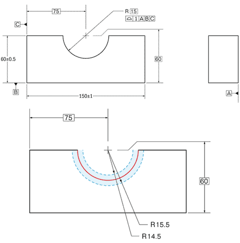
3. Unequally Disposed Tolerances

[/et_pb_text][et_pb_text _builder_version=”4.16″ _module_preset=”default” text_font=”Lato||||||||” text_text_color=”#292929″ text_font_size=”17px” custom_margin=”||21px|||” global_colors_info=”{}”]Such tolerances are directly opposite from the previous ones. They are variations from the given specifications (true profile) that are permitted in opposite dimensions unequally. You can see the way it works in the infographics below.[/et_pb_text][et_pb_image src=”http://ecoreprap.com/wp-content/uploads/2022/02/Unequally-Disposed-Profile-Tolerance.png” alt=”Unequally-Disposed-Profile-Tolerance” title_text=”Unequally-Disposed-Profile-Tolerance” align=”center” _builder_version=”4.16″ _module_preset=”default” global_colors_info=”{}”][/et_pb_image][et_pb_text _builder_version=”4.16″ _module_preset=”default” text_font=”Lato||||||||” text_text_color=”#292929″ text_font_size=”17px” custom_margin=”||21px|||” global_colors_info=”{}”]Typically, limits for each of the directions are indicated in specifications for a particular component. For instance, the diameter of a hole to be drilled is 30.0 mm. and the tolerance required is 0.1 again. Upper and lower limits may look like 29.99 and 30.09, or 29.93 and 30,03, respectively, or anything like this.

The crucial point is that the upper and lower limits are not distributed from given dimensions equally.[/et_pb_text][et_pb_text _builder_version=”4.16″ _module_preset=”default” text_font=”Lato||||||||” text_text_color=”#292929″ text_font_size=”17px” custom_margin=”||11px|||” global_colors_info=”{}”]

4. Unilateral Tolerances

[/et_pb_text][et_pb_text _builder_version=”4.16″ _module_preset=”default” text_font=”Lato||||||||” text_text_color=”#292929″ text_font_size=”17px” custom_margin=”||21px|||” global_colors_info=”{}”]Such errors represent the strict version of unequally disposed tolerances. Unilateral tolerances are variations from the given specifications that are permitted in one direction only. You can see the way it works in the infographics below.[/et_pb_text][et_pb_image src=”http://ecoreprap.com/wp-content/uploads/2022/02/Unilaterally-Disposed-Profile-Tolerance.png” alt=”Unilaterally-Disposed-Profile-Tolerance” title_text=”Unilaterally-Disposed-Profile-Tolerance” align=”center” _builder_version=”4.16″ _module_preset=”default” global_colors_info=”{}”][/et_pb_image][et_pb_text _builder_version=”4.16″ _module_preset=”default” text_font=”Lato||||||||” text_text_color=”#292929″ text_font_size=”17px” custom_margin=”||21px|||” global_colors_info=”{}”]Unilateral tolerances also should be mentioned in the specifications for a component, as any manufacturer sticks to bilateral tolerances within an equipment unit’s standard errors. Unless otherwise is not mentioned.

A respective example is the 30 mm. diameter hole. Tolerance is 0.1 mm one more time. In this case, upper and lower limits would be either 29.9 mm. and 30.0 mm., or 30.0 mm. and 30.1 mm., respectively.

The crucial point is that the entire distribution is allowed in one direction only, while in the other one any error is not acceptable et al. [/et_pb_text][et_pb_text _builder_version=”4.16″ _module_preset=”default” text_font=”Lato||||||||” text_text_color=”#292929″ text_font_size=”17px” custom_margin=”||11px|||” global_colors_info=”{}”]

5. Limit Tolerances

[/et_pb_text][et_pb_text _builder_version=”4.16″ _module_preset=”default” text_font=”Lato||||||||” text_text_color=”#292929″ text_font_size=”17px” custom_margin=”||21px|||” global_colors_info=”{}”]You may have heard of limit tolerances as of hole & shaft tolerances. Basically, this system divides standard errors into two categories: hole and shaft. They are given particular labels, with which you can familiarize yourself from the infographics below.[/et_pb_text][et_pb_image src=”http://ecoreprap.com/wp-content/uploads/2022/02/F1_S.S_Madhu_13.12.19_D1.png” alt=”hole and shift tolerance zone” title_text=”hole and shift tolerance zone” align=”center” _builder_version=”4.16″ _module_preset=”default” global_colors_info=”{}”][/et_pb_image][et_pb_text _builder_version=”4.16″ _module_preset=”default” text_font=”Lato||||||||” text_text_color=”#292929″ text_font_size=”17px” custom_margin=”||21px|||” global_colors_info=”{}”]
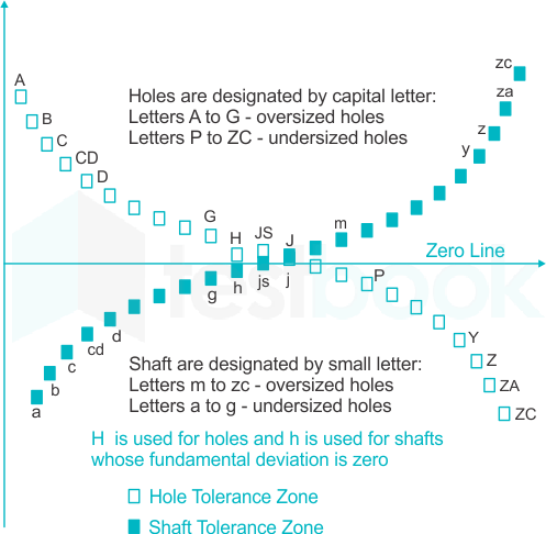
The thing is, these standards needed to fit parts in each other. For this purpose, the dimensions of a hole are always larger than the ones of shafts. For instance, it may be requested that the base dimension of a hole is 30.0 mm., and upper and lower limits are 30.0 mm. and 30.1 mm. only.

At the same time, a shaft required may be 30 mm. in diameter, and its upper and lower limits would be 29.9 and 30.0 mm only. It is done for the purpose that a shaft is always smaller than a hole because any machine unit is mistaken to a defined extent. But, this mistake will only help fit the shaft in a hole.

The crucial point is that a hole is always permitted to be slightly higher in size than basic requirements demand, while a shaft is slightly lower in size.[/et_pb_text][et_pb_text _builder_version=”4.16″ _module_preset=”default” text_font=”Lato||||||||” text_text_color=”#292929″ text_font_size=”17px” custom_margin=”||11px|||” global_colors_info=”{}”]

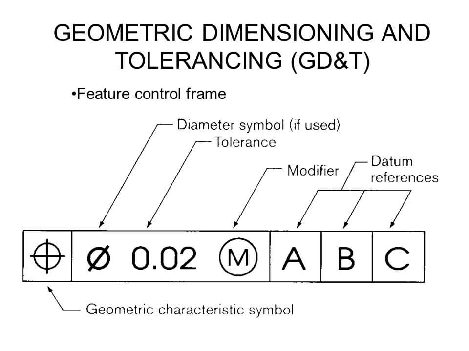
6. Geometric Dimensioning and Tolerancing

[/et_pb_text][et_pb_text _builder_version=”4.16″ _module_preset=”default” text_font=”Lato||||||||” text_text_color=”#292929″ text_font_size=”17px” custom_margin=”||21px|||” global_colors_info=”{}”]In common sense, geometric dimensioning and tolerancing (GD&T) do not define particular variances from the base dimension. It rather assists in indicating such tolerances in specifications. 

GD&T is a system that incorporates symbols that define geometric characteristics of a component, its modifiers, tolerances, and datum references (a particular line, point, or axis). You can see an example of a coded requirement to a component to manufacture in the infographics below.[/et_pb_text][et_pb_image src=”http://ecoreprap.com/wp-content/uploads/2022/02/Geometric-Dimensioning-and-Tolerancing.jpg” alt=”Geometric Dimensioning and Tolerancing” title_text=”Geometric Dimensioning and Tolerancing” align=”center” _builder_version=”4.16″ _module_preset=”default” global_colors_info=”{}”][/et_pb_image][et_pb_text _builder_version=”4.16″ _module_preset=”default” text_font=”Lato||||||||” text_text_color=”#292929″ text_font_size=”17px” custom_margin=”||21px|||” global_colors_info=”{}”]In case you have to read someone’s pieces of symbolic language, or you are required to write one yourself, you can always consult GD&T standards. You will be surprised how simple it is to write coded specifications when you have all the symbols listed and explained.[/et_pb_text][et_pb_text _builder_version=”4.19.0″ _module_preset=”default” text_font=”Lato||||||||” text_text_color=”#292929″ text_font_size=”17px” custom_margin=”||21px|||” global_colors_info=”{}”]

Reference Post: 4 Types of CNC Machining Offset You Need to Know

[/et_pb_text][et_pb_text _builder_version=”4.16″ _module_preset=”default” text_font=”Lato||||||||” text_text_color=”#292929″ text_font_size=”17px” custom_margin=”||11px|||” global_colors_info=”{}”]

Tips for Choosing the Tolerances

[/et_pb_text][et_pb_text _builder_version=”4.16″ _module_preset=”default” text_font=”Lato||||||||” text_text_color=”#292929″ text_font_size=”17px” custom_margin=”||21px|||” global_colors_info=”{}”]But here’s the interesting thing. We determined five major aspects that should be considered while deciding what of the described tolerances suit your purposes better. It is also correct for the selection of standard errors and determining criteria of acceptance for particular components.[/et_pb_text][et_pb_text _builder_version=”4.16″ _module_preset=”default” text_font=”Lato||||||||” text_text_color=”#292929″ text_font_size=”17px” custom_margin=”||11px|||” global_colors_info=”{}”]

1. High costs of tight requirements

[/et_pb_text][et_pb_text _builder_version=”4.16″ _module_preset=”default” text_font=”Lato||||||||” text_text_color=”#292929″ text_font_size=”17px” custom_margin=”||21px|||” global_colors_info=”{}”]Requesting tighter requirements than basic ones (0.1 mm. for CNC machining, for instance) is associated with high expenses in 100% of cases. The simple explanation is that stricter requirements trigger a sequence of actions needed to comply with given acceptance criteria.

Additionally, a manufacturer may not have a CNC machine precise enough. As it has been mentioned multiple times throughout the text, all automated centers have an error they had been designed with. The more expensive the equipment unit is, the higher its grade, and the lower variance can be supported respectively.

Even if a manufacturer has a CNC machine precise enough to fulfill your strict requirement, it will definitely require its settings to be adjusted. This process is time-consuming and also contributes to the final production costs.[/et_pb_text][et_pb_text _builder_version=”4.16″ _module_preset=”default” text_font=”Lato||||||||” text_text_color=”#292929″ text_font_size=”17px” custom_margin=”||11px|||” global_colors_info=”{}”]

2. Inspection

[/et_pb_text][et_pb_text _builder_version=”4.16″ _module_preset=”default” text_font=”Lato||||||||” text_text_color=”#292929″ text_font_size=”17px” custom_margin=”||21px|||” global_colors_info=”{}”]This aspect that impacts costs of tight tolerance requirements is based on the Quality Assurance policies. Basically, any component manufactured by CNC machines must pass a control that confirms or rejects their compliance with specifications.

The major difficulty with unjustified tolerances is that higher amounts of resources are required to check parts for their quality. Inspection machines should be adjusted as well, leading to the turnaround time deterioration.

In the worst-case scenario, a manufacturer may not have inspection machines with a suitable grade. Most precise equipment units are needed to find the slightest discrepancies between specifications and dimensions obtained.[/et_pb_text][et_pb_text _builder_version=”4.16″ _module_preset=”default” text_font=”Lato||||||||” text_text_color=”#292929″ text_font_size=”17px” custom_margin=”||11px|||” global_colors_info=”{}”]

3. Choice of manufacturing methods

[/et_pb_text][et_pb_text _builder_version=”4.16″ _module_preset=”default” text_font=”Lato||||||||” text_text_color=”#292929″ text_font_size=”17px” custom_margin=”||21px|||” global_colors_info=”{}”]It is a broad topic to discuss, but we tried to explain the key nuances briefly. Tolerances may depend on the manufacturing method chosen. For instance, drilling may be more precise than turning or milling.

Equipment units with a different number of axes fulfill distinct functions and also may have different basic tolerances. Additional operations such as finishing may impact the initial dimensions, which also should be considered.

In essence, there are numerous manufacturing operations, and for every distinct one, appropriate tolerances are chosen, which impact the costs of finished components.[/et_pb_text][et_pb_text _builder_version=”4.16″ _module_preset=”default” text_font=”Lato||||||||” text_text_color=”#292929″ text_font_size=”17px” custom_margin=”||11px|||” global_colors_info=”{}”]

4. Dependency between the tolerances and the material

[/et_pb_text][et_pb_text _builder_version=”4.16″ _module_preset=”default” text_font=”Lato||||||||” text_text_color=”#292929″ text_font_size=”17px” custom_margin=”||21px|||” global_colors_info=”{}”]Basically, the mechanical properties of a material to be manufactured also define what tolerances are more or less achievable. Hardness, density, abrasiveness, and heat stability, are the major factors that define the degree of a material’s responsiveness to stress applied.

You would be surprised if you knew how the costs of compliance with non-standard requirements for softer and harder metals differ. And, that is more confusing, there is no a certain dependency because any property of metal may make the material easier or harder to machine with a minor error.[/et_pb_text][et_pb_text _builder_version=”4.16″ _module_preset=”default” text_font=”Lato||||||||” text_text_color=”#292929″ text_font_size=”17px” custom_margin=”||11px|||” global_colors_info=”{}”]

5. Cases when the choice of tight tolerances is due

[/et_pb_text][et_pb_text _builder_version=”4.16″ _module_preset=”default” text_font=”Lato||||||||” text_text_color=”#292929″ text_font_size=”17px” custom_margin=”||21px|||” global_colors_info=”{}”]In some situations, you have no other option but to request a manufacturer to tighten the variances. It is mainly done for innovative prototypes that should be perfectly machined to be appropriately tested.

Alternatively, you will always need CNC machines to operate with extra small errors (±0.0005″) when you produce electronic components.

Finally, in some designs and machining operations, tolerances may be adjusted by the change of cutting tools. This way, you may select the tightest tolerances possible without being additionally charged, as a manufacturer does not waste resources to respond to your request.[/et_pb_text][et_pb_text _builder_version=”4.16″ _module_preset=”default” text_font=”Lato||||||||” text_text_color=”#292929″ text_font_size=”17px” custom_margin=”||11px|||” global_colors_info=”{}”]

Final Take

[/et_pb_text][et_pb_text _builder_version=”4.16″ _module_preset=”default” text_font=”Lato||||||||” text_text_color=”#292929″ text_font_size=”17px” custom_margin=”||21px|||” global_colors_info=”{}”]So, what does all this mean? Tolerances are a crucial aspect of CNC machining. The choice of these variances mostly depends on CNC machines’ capacities and requirements for a particular component.

You are highly recommended to justify tolerances before requesting the manufacturer to craft a component according to strict specifications. In many cases, basic CNC machining tolerances suit well, while unnecessary tightening of them leads to extra expenses. [/et_pb_text][/et_pb_column][et_pb_column type=”1_3″ _builder_version=”4.16″ _module_preset=”default” custom_padding=”5px|10px|5px|10px|false|false” sticky_position=”top” sticky_limit_bottom=”row” border_radii=”on|20px|20px|20px|20px” box_shadow_style=”preset1″ box_shadow_blur=”50px” box_shadow_color=”rgba(0,0,0,0.08)” global_colors_info=”{}”][et_pb_text _builder_version=”4.16″ _module_preset=”default” text_font=”Lato||||||||” text_text_color=”#292929″ text_font_size=”20px” header_3_font=”Lato|700|||||||” custom_margin=”20px||13px||false|false” global_colors_info=”{}”]

Need Any Services? Contact Us Now!

[/et_pb_text][et_pb_sidebar _builder_version=”4.16″ _module_preset=”default” body_font=”Lato||||||||” body_text_color=”#0C71C3″ body_font_size=”17px” text_orientation=”left” custom_margin=”||15px||false|false” custom_padding=”||0px||false|false” global_colors_info=”{}”][/et_pb_sidebar][dsm_contact_form_7 cf7_library=”10464″ _builder_version=”4.16″ _module_preset=”default” labels_font=”Lato||||||||” labels_text_color=”#292929″ labels_font_size=”17px” placeholder_text_color=”#292929″ placeholder_font_size=”17px” radio_checkbox_font=”Lato||||||||” radio_checkbox_text_color=”#292929″ radio_checkbox_font_size=”17px” custom_button_one=”on” button_one_text_color=”#FFFFFF” button_one_bg_color=”#0C71C3″ button_one_border_radius=”10px” button_one_font=”Lato|700|||||||” button_one_use_icon=”off” global_colors_info=”{}”][/dsm_contact_form_7][/et_pb_column][/et_pb_row][/et_pb_section]

Leave a Reply

Your email address will not be published. Required fields are marked *