Updated: December 04, 2023
hatter is an undesired effect during CNC machining that manufacturers have to deal with. It appears in multiple machining operations, including milling, turning, and drilling. Chatter negatively affects the quality of machining and the span life of a cutting tool.
Chatter is sometimes hard to spot. More than that, there are different types of it. Let’s find out what chatter actually is and how to reduce it.
Chatter is simply the unwanted vibration that appears during a cutting process. Chatter vibrations produce fluctuations on the surface of the components being processed. Multiple triggers, such as tool holders, cutting tools, part fixtures, and machine settings, lead to the effect. The end outcome of chatter is typically a poor surface finish.
There are two types of machine vibrations — resonating and non-resonating. The first normally appears when you use unevenly worn tools. They are nonconstant throughout the machining cycle.
You can make a machine to produce vibrations that are close to natural frequencies. The positive effect is achievable if you approach spindle speeds, feed rates, tooling, design nuances, and other aspects correctly. This way, only at certain points of machining, such as when you make concave corners, would the machine experience resonating vibrations.
Take a look at what chatter marks may look like in the image below.

If you switch from resonating and non-resonating vibrations, you’ll see that there are two major types of chatter:
Milling cutters are prone to vibrations in the first place. They start trimming and transferring the vibration to the workpiece. This way, the tool and the workpiece start slipping against each other, increasing the magnitude of chatter.
Occasionally, you have the workpiece incorrectly fixed on a milling machine’s worktable. It may cause some offsets and vibrations. But more than that, the workpiece’s thin wall may vibrate, transferring the chatter as well.
Some shatter is unavoidable. But in case you wonder to what extent it’s acceptable — consider 100μm your benchmark. If the vibration or fluctuations on the surface are less than this value, there will be no obvious scratches. If it’s more than 100μm, you should do something about your workpiece or tool chatter.
Every manufacturer knows how to approach their milling machines to reduce undesired vibrations. Let’s focus on the five most essential pieces of advice that heavily impact the end outcome of machining.
It’s probably the most important aspect in cutting to consider. Milling can be divided into downward and upward milling. If the direction in which you apply the cutting force is consistent with the clamping direction, the bent part and chatter can be reduced notably.
Besides, as far as you know, a CNC mill is equipped with a ball screw. Because of the specificity of this technology, it appears that vertical machining centers are more helpful in eliminating chatter.
The other aspect to consider is how the degree of the tool engagement varies in the machining. You need to know that using a constant meshing tool path alleviates the chatter instantly.
Usually, with conventional milling, the degree of cutter engagement is a variable. It happens that too much force is applied to the cutter from time to time as the tool goes along the path.
The best way to reduce chatter in this phase is to achieve a constant engagement toolpath. Or to reduce the depth of cut as an option.
Besides, you should reconsider the spindle speed setting. For one, if you find resonant chatter to be the use, try to increase or decree the RPM value by 5%. It’ll help to eliminate most of the resonant vibrations.
A quick tip: Some CAM software enables you to set constantly varying spindle speeds. Some manufacturers love this feature.
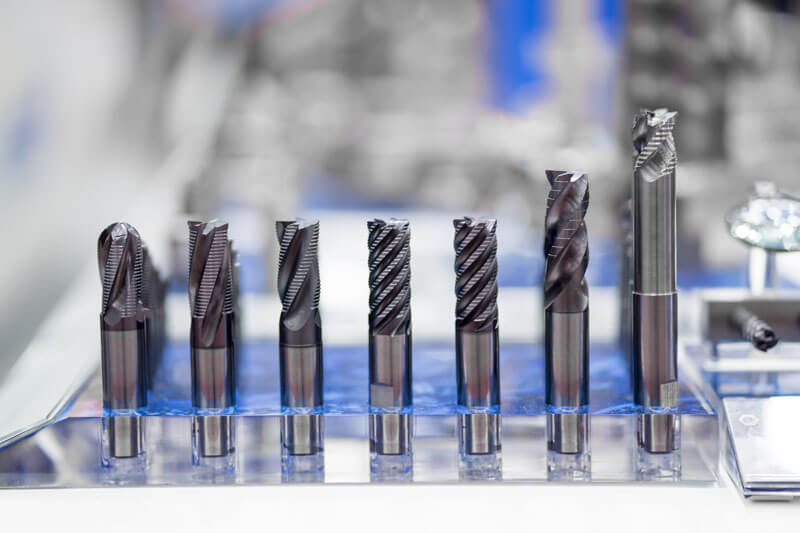
Tool chatter is harder to get rid of compared to workpiece chatter. Considerations in choosing the right tooling include:
Engineers tend to use the largest tool that can be accommodated as long as it meets the technical requirements. The thing that more solid a cutter is, the less it’s prone to chatter. Long, thin tools deflect the most, so consider choosing the shortest one with the largest diameter.
You should also minimize the number of tools protruding from the holder and ensure that they are fixed as tightly as possible. This way, they will be less likely to hang out and vibrate. An effective way to alleviate vibration is to combine different tools with variable groove shapes.
There’s another point you should be aware of. The use of sharp blades reduces the cutting force of the tooling. That’s why the timely maintenance of tooling, with the consideration of the processing environment, is due.
It’s also essential to apply the correct and continuous tool pressure so the chip load is consistent.
As mentioned multiple times, incorrect positioning and fixing of workpieces and cutters are the primary causes of chatter. for one, ordinary tool holders like side lock, double-angle chuck, and standard ER chuck cannot provide the required precision. They are unsuitable for high-performance machining.
A much better choice is the tool holder that would combine end face and taper contact to provide higher rigidity. Such a type of retainer engages with the precision ground surface of the spindle. The balance of tools should be evaluated for better adjustment. This way, the surface quality can always be improved even at the lowest RPM.
As for the work holder, you should check whether the chuck, vise, vacuum table, or another holding device can apply sufficient pressure to the workpiece and keep it firmly fixed. You may consider using a work fixture to apply clamping pressure as recently as it’s only possible.
But make sure to avoid clamping only one end of a long, thin workpiece. Use a tailstock or some form of a stable rest frame for such components.
With thin-walled parts, the shock-absorbing can be challenging. To alleviate chatter, you may use filler materials to increase the overall stiffness of the workpiece.
In case you never thought about it, the way your machine is arranged also shares a key role. As a rule, a CNC machine should be installed on a sol concrete floor without cracks or discontinuities of any other sort.
The issue is that soft, elastic, or damaged flow may aggravate the jitter of a CNC unit. Consider using anchors and adjusting feet properly to minimize chatter.

Chatter is the effect that is hard to deal with. It’s impacted by numerous factors starting from where you installed your machine and ending with what the toolpath is in a particular CNC design.
Should you experience undesired vibration, examine the issues thoroughly. Make sure the tool and workpiece are held correctly, and the settings chosen are appropriate. Play with RPM and ensure your cutters are not worn.