In Geometric Dimensioning and Tolerancing(GD&T), arc length symbol is used to control the length of a piece of arc on a curved line or surface.
The GD&T arc length symbol is commonly used in various parts with specific circular or cylindrical features. This article will provide a guide of GD&T arc length symbol.
Key Takeaways:
The GD&T arc length symbol (⌒) precisely defines curved distance measurements on engineering drawings per ASME Y14.5 standards.
Arc length ensures functional performance in curved assemblies, motion mechanisms, and fluid systems by controlling arc length accuracy.
Multiple measurement methods—from high-precision CMMs to production gauges—verify arc length compliance across different manufacturing scenarios.
The arc length symbol, also named as the arc modifier symbol in Geometric Dimensioning and Tolerancing(GD&T), is used to state that a dimension value indicated on the engineering drawing refers to the length of an arc on a curved outline, instead of the linear dimension between two points.
According to the ASME Y14.5 standards, the dimension value for the arc length would be commonly applied to the surface nearest to the dimensional indication by default.
However, it is particularly common that the arc length symbol would be usually used on the centerline of a part, especially those with a lot pipe bending. In such cases, the specific part where the arc length symbol is applied to must be clearly indicated on the drawing by specification.
In other words, as long as the GD&T arc length symbol is not used on the closest surface to the dimension value as default situation, it must be clearly specified on the drawing.
In Geometric Dimensioning and Tolerancing, the arc length symbol is indicated as a standard arc, like “ ⌒”.
In addition, as a dimension modifier symbol, the arc length symbol is not indicated within the feature control frame of the specific feature.
Instead, the GD&T arc length symbol is usually indicated directly above the specific dimension value on engineering drawings. The tolerance will be indicated after the dimension value.
More importantly, it is critical to indicate the beginning point and the end of the specifically controlled arc. Usually, two ends of the arc would be indicated out and be connected with dimension lines.
At the same time, the central angle of the arc can also be indicated on the drawing to specify more clearly.
The dimension lines of the arc length can be orthogonal or radial. It depends on the included central angle. If the included angle of the arc is less than 90°, orthogonal extension lines will be used.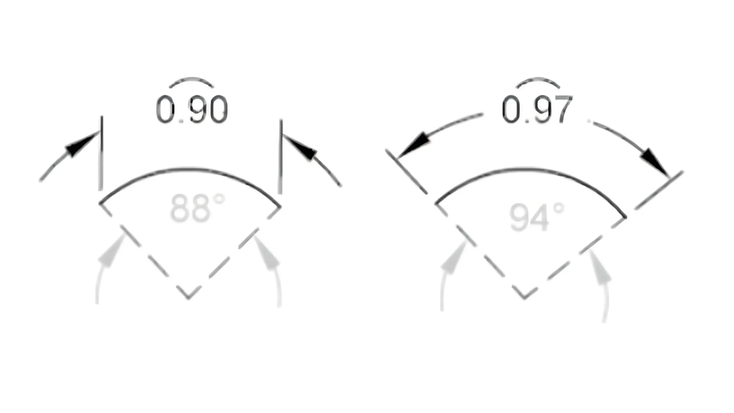
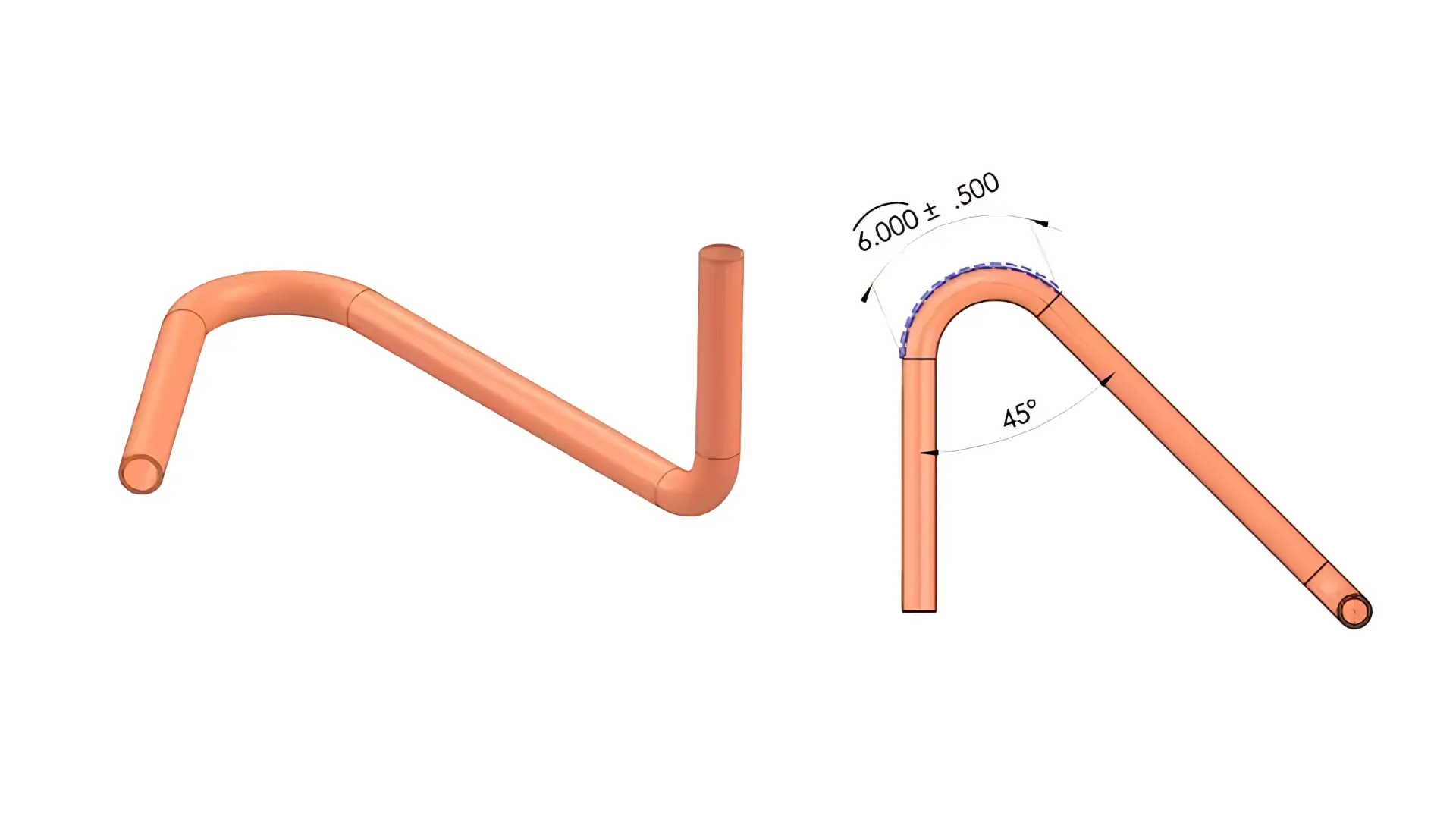
For instant, on the below model drawing, the arc length dimension is shown to be 6.000+/-.500. And a blue dashed line is indicated on this model to state the feature which the dimension is applied to.
In this case, the arc length dimension and its tolerance are applied to the surface closest to the dimension by default.
And the central angle is also indicated on the drawing. What’s more, as the central angle is 45°, which is less than 90°, orthogonal extension lines are used to indicate the specific arc.
The GD&T arc length symbol is particularly used on the components with curved surfaces, curved profiles, or arced features.
The functions of arc length symbol mainly focus on curved features, motion-related assemblies, and functional performance.
The GD&T arc length precisely controls the length of a specific arc, thus to ensure proper assembly, motion, and working performance as designed.
The concrete functions are as follows:
When two parts are required to assembled with each other on curved surfaces, like the arc-shaped contact between a bearing outer ring and its housing, arc lengths must match with each other to ensure sufficient contact area.
Mismatches would lead to excessive stress or loose fits, and would further accelerate localized wear or vibration.
For instant, if the arc length of a bearing housing groove is shorter than that of the bearing outer ring, the bearing would not be fully seated, while if too long, the bearing may wobble.
For parts relying on curved paths such as cams and rocker arms, the arc length directly corresponds to motion travel. By specifying arc length tolerances, the GD&T arc length symbol precisely controls the motion trajectory of components, thus preventing insufficient or excessive travel.
For example, if the designed arc length of a cam’s rise segment is 50mm with a ±0.05mm tolerance, an actual shorter arc length would prevent the follower from reaching the intended position, causing functional failure.
For fluid pathways like curved channels in pipes or valves, arc length determines the “path length.” An overly short arc length may cause abrupt velocity changes, thus leading to noise or pressure loss, while an overly long arc length would increase flow resistance, and then reduce efficiency.
For assemblies with curved profiles like nested arc-shaped housings, arc lengths must satisfy envelope requirements. In other words, the inner part’s arc length must be equal to or smaller than the outer part’s arc length for clearance fit, or tolerances must prevent interference.
For example, the arc length of a car steering wheel’s decorative trim must match that of the steering column cover. Excessive trim arc length may cause jamming, while insufficient length would create excessive gaps and compromises dust resistance.
Arc length is often combined with other geometric tolerances such as GD&T profile or GD&T circularity to jointly control the precision of curved features.
For example, specifying arc length 50mm with profile tolerance 0.02mm controls both length and form deviation (e.g., departure from the theoretical arc).
GD&T arc length is commonly used on parts with curved surfaces, curved profiles, or arc-shaped features. Below is the list of main applications of GD&T arc length symbol:
Cams and Followers: The arc length on a cam profile directly determines the travel and motion trajectory of the follower, like the arc lengths of the rise, dwell, and return segments.
Excessive deviation in arc length would disrupt the follower’s motion rhythm and then cause excessive speed or insufficient travel, affecting mechanism efficiency or even causing jamming.
Gears and Racks: The control of arc length in the curved segments of gear tooth profiles (e.g., the transition arcs of the addendum and dedendum circles) plays critical role in ensuring contact accuracy and reducing impact and wear during meshing.
Links and Rocker Arms: For parts with curved motion trajectories like the curved working surface of an engine rocker arm, the arc length determines the swing range and force distribution, preventing motion interference due to arc length deviations.
Pipes and Elbows: The arc length of the curved section in an elbow directly affects the flow resistance and path of fluid. For example, an overly short arc length in an HVAC pipe elbow can cause turbulence, increasing energy consumption, while an overly long arc length may lead to interference with other components.
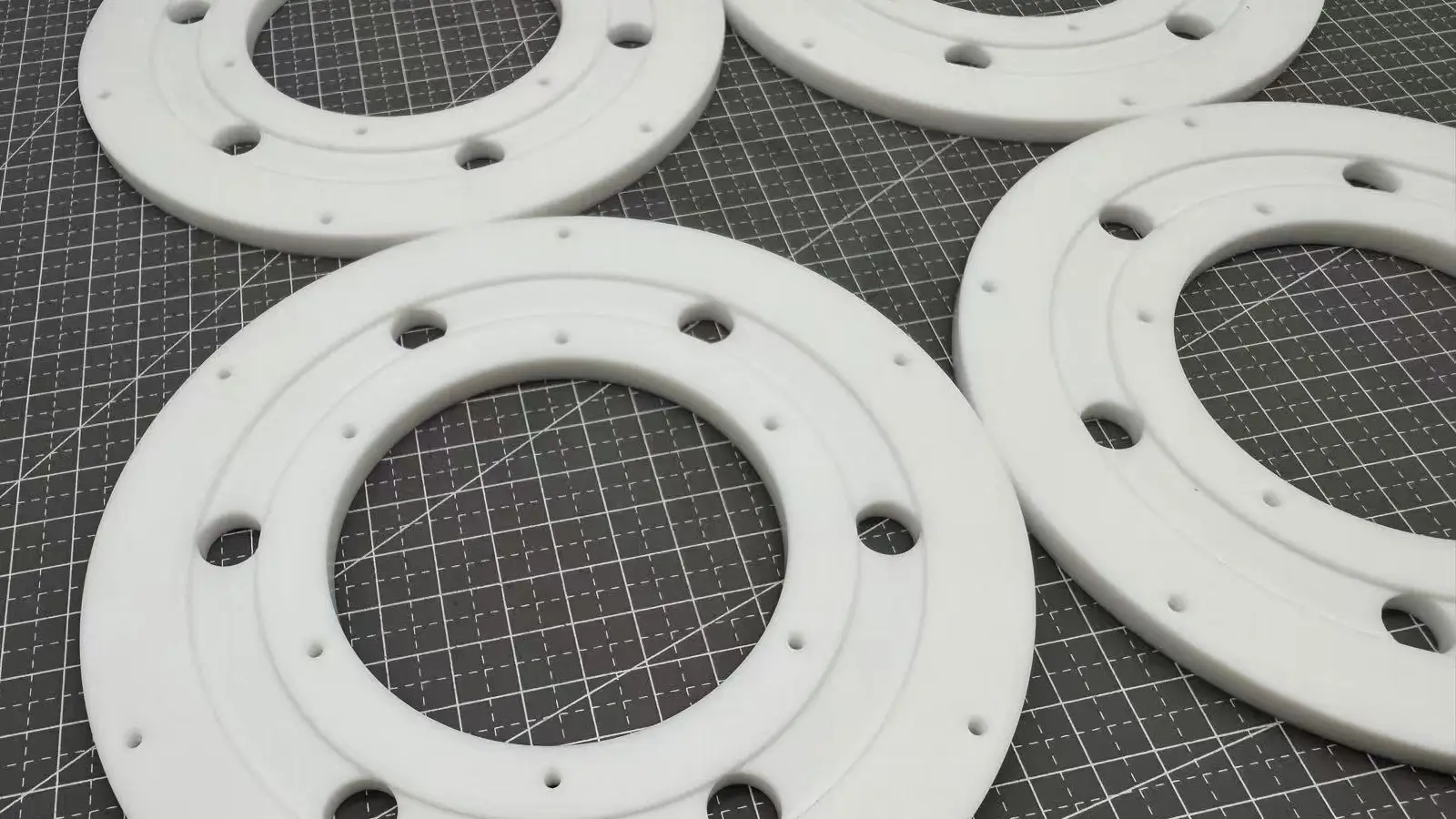
Seals and Flanges: The arc length of circular seals such as the cross-sectional arc of an O-ring or the sealing surface of curved flanges must match that of the mating part. Otherwise, leaks may appear due to insufficient contact area.
Bearings and Shaft Journals: Controlling the arc length of the curved transition section like the fillet arc of a shaft shoulder can reduce stress concentration and ensure proper fit between the bearing inner ring and the shaft, preventing bearing misalignment.
Molds and Stamped Parts: The arc length of the curved cutting edge in a stamping die (e.g., the curved edges of automotive body panels) determines the forming accuracy of stamped parts. Excessive deviations in arc length would lead to wavy edges or dimensional inaccuracies.
Cutting Tools and Blades: The arc length of curved tools such as radius end mills or ball-nose cutters directly affects surface roughness and shape accuracy (e.g., uniform machining allowances for curved parts).
Architectural and Aerospace Structures: The arc length of curved beams, domes, and other structural components must meet mechanical load requirements. Improper deviations would cause stress concentration and then increase safety risks.
In Geometric Dimensioning and Tolerancing(GD&T), arc length refers to the curvilinear distance between two points on a circular arc. The arc’s deviation directly affects the assembly and functional performance of parts.
The methods for inspecting GD&T arc length are selected based on factors such as precision requirements, production batch, and dimensional size. Common methods are as follows:
By collecting points on the arc through a contact probe, and fit the arc’s center, radius and central angle, CMMs can then measure arc length via arc length formula(arc length =radiusⅹcentral angle).
With high measuring precision and ability to output specific values, CMMs are suitable for measurements on high-precision part and complex structural parts.
However, the efficiency is low to some extent, so CMMs are often used for small batches or sampling inspections.
Steps:
As a kind of non-contact optical measurement, vision measuring machines can capture images of the arc surface through high-definition lens, which can prevent parts from being damaging.
With higher efficiency than CMMs and medium measuring precision, they are suitable for batch sampling inspections.
Vision measuring machines are also particular used on measurement for parts with small or medium size, or with smooth surfaces, such as electronic components and precision stamped parts.
Steps:
Laser scanners can collect large amounts of points on a single arc and is also a kind of non-contact measurement with high measuring precision.
Therefore, they are suitable for large parts and parts with complex curved surfaces. But the cost is certainly high.
Steps:
Standard gauges can be manufactured to inspect whether the part is qualified or not according to the designed arc length and its tolerance.
These special gauges usually include go gauges and no-go gauges. For go gauges, the arc length is equal to the upper tolerance limit. The part should fit the go gauge without clearance.
For no-go gauges, the arc length is equal to the upper tolerance limit. The part is required to not fit the no-go gauge.
With extremely high efficiency, they are recommended to be used on mass production such as standard parts or bearing outer rings. And they are simple to operate
However, they can only judge qualification but cannot output specific values. Meanwhile, gauges need to be calibrated regularly.
Arc length can also be measure simply by fitting the arc surface with a bendable flexible ruler such as a steel tape or a fiber tape.
The cost is extremely low. But the measuring precision is also certainly low(hugely affected by manual reading).
They are suitable for rough inspection on low-precision part or large parts like storage tanks.
The GD&T arc length symbol (⌒) is a fundamental yet powerful tool for precisely controlling the linear distance along a curved feature. As detailed throughout this guide, its proper application ensures not only dimensional accuracy but also functional performance in assemblies involving motion, fluid transfer, and curved surface contact.
By clearly defining the length of an arc—rather than a straight-line chord—this symbol helps eliminate ambiguity on engineering drawings, thereby improving manufacturing consistency and inspection reliability. From cam mechanisms and piping systems to critical sealing surfaces, the arc length tolerance plays a vital role in maintaining design intent across a wide range of industrial applications.
When applying the arc length symbol, designers should always:
Clearly indicate the start and end points of the arc.
Specify whether the dimension applies to the centerline, surface, or other features if not the nearest surface.
Combine with other GD&T symbols like profile tolerance where necessary to control both size and form.
For complete guidelines on usage and interpretation, always refer to the latest ASME Y14.5 standard.

Lucas is a technical writer at ECOREPRAP. He has eight years of CNC programming and operating experience, including five-axis programming. He’s a lifelong learner who loves sharing his expertise.

Cylindricity is to control the overall deviation of a cylindrical surface from a perfect geometric cylinder.

Parallelism GD&T is to ensure that the reference surface or axis is parallel to the datum surface or axis.

Perpendicularity GD&T is used to control the measured surface or axis, keeping 90° with the datum surface or axis.

GD&T angularity GD&T is used to control a particular angle between the specified feature and the datum feature