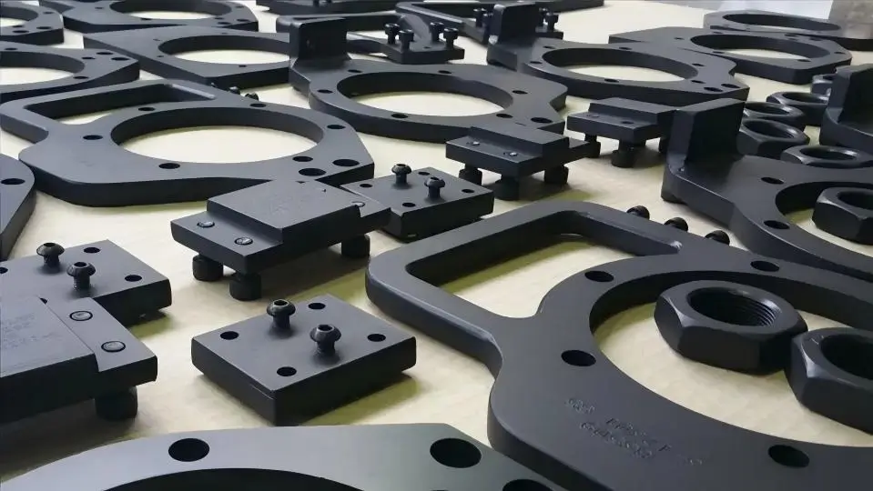
Anodized CNC machined drone parts are precision components produced by CNC milling or turning and enhanced through anodizing to meet UAV requirements for low weight, strength, and durability.
For manufacturers seeking CNC machining parts for uav, CNC machining ensures tight tolerances, complex geometries, and dimensional consistency, while anodizing forms a hard aluminum oxide layer that improves corrosion resistance, wear resistance, electrical insulation, and thermal stability with minimal weight gain.
Common materials include 6061 aluminum for cost-effective structures, 7075 aluminum for high-load components, magnesium alloys for ultra-lightweight designs, and titanium for critical aerospace applications.
Type II anodizing provides thin, dyeable coatings for general protection, while Type III hard anodizing delivers thick, steel-like surface hardness for high-wear environments.
Effective design must account for coating thickness, edge radii, hole geometry, and tolerance compensation.
Together, CNC machining and anodizing form a functional manufacturing system that directly determines drone reliability, service life, and performance across consumer, industrial, and military applications.
CNC machined drone parts refer to precision components manufactured using Computer Numerical Control (CNC) milling or turning processes, specifically designed for unmanned aerial vehicles (UAVs).
This manufacturing method enables extremely high precision, complex geometries, and excellent dimensional consistency, meeting the strict requirements of drones for lightweight construction, high strength, and long-term reliability.
Anodized surface finishing is an electrochemical process that forms a hard, dense oxide layer on the metal surface, significantly improving surface performance.
When combined with CNC machining, anodizing provides the following key advantages for drone components:
| Material | Characteristics | Typical Applications |
|---|---|---|
| Aluminum Alloy 6061 | Well-balanced mechanical properties, easy to machine, and cost-effective; widely used in commercial drones. | Frames, brackets, mounting components |
| Aluminum Alloy 7075 | Very high strength, close to steel, with excellent fatigue resistance; suitable for high-stress components. | Rotor arms, landing gear, high-load joints |
| Magnesium Alloy | Extremely low density (about 30% lighter than aluminum) with good vibration damping, but lower corrosion resistance, requiring strict surface treatment. | Racing drones, ultra-lightweight UAV structural parts |
| Titanium Alloy | Outstanding strength-to-weight ratio, excellent corrosion and heat resistance, but high machining cost. | Military UAVs, industrial long-endurance drones, critical load-bearing components |
CNC machining delivers the precise geometries required for drone components, while anodized surface treatment provides durable and reliable surface performance.
Together, they form an indispensable manufacturing combination for producing high-performance, long-lasting drones—whether consumer-grade, industrial, or military.
Optimal results depend on precise matching of materials, machining accuracy, and anodizing processes based on mission requirements, operating environments, and cost considerations.
From both engineering design and procurement perspectives, anodizing is far more than surface decoration—it is a core functional requirement.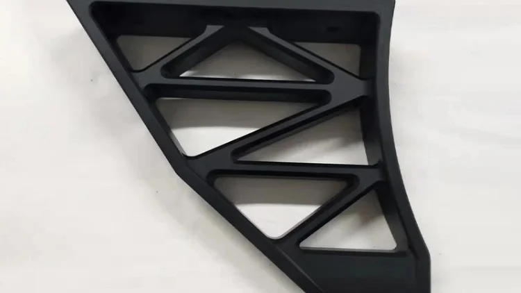
For high-precision equipment like drones that operate in demanding environments, surface treatment choices directly impact performance, reliability, and service life.
Requirement: Drones are extremely sensitive to weight. Even a 1-gram increase can affect flight time, maneuverability, and payload capacity.
How anodizing helps:
Requirement: Drones often operate in humid, salty, or dusty environments. Untreated aluminum is prone to corrosion, leading to structural degradation and electrical failures.
How anodizing helps:
Requirement: Drone components experience frequent mechanical contact—battery replacement, gimbal adjustments, propeller installation—all of which cause surface wear.
How anodizing helps:
Requirement: Drone motors, ESCs, and batteries generate heat during operation. Surface materials must withstand temperature fluctuations without degradation.
How anodizing helps:
Requirement: Drone airframes house sensitive electronic systems and must prevent short circuits and electromagnetic interference.
How anodizing helps:
Requirement: Drones require a professional appearance, clear part identification, and brand recognition. Traditional paint adds weight and is prone to peeling.
How anodizing helps:
| Surface Treatment | Initial Cost | Maintenance Cost | Total Cost of Ownership | Suitability |
|---|---|---|---|---|
| Anodizing | Medium | Low | Low | High |
| Painting | Low | High | Medium | Medium |
| No Treatment | None | Very High | High | Not Recommended |
Although anodizing increases initial manufacturing costs by approximately 15–30%, it delivers positive returns across the product lifecycle by:
Anodizing is not an optional “value-add” for CNC machined drone parts—it is a fundamental engineering requirement that ensures performance, reliability, and cost efficiency.
As drone applications expand from consumer entertainment into industrial inspection, agriculture, emergency response, and military reconnaissance, surface treatment requirements will only become more demanding.
Experienced engineers and procurement professionals recognize anodizing as an indispensable step in drone component manufacturing.
This is not an added cost—it is an investment in long-term product value, reliability, and competitiveness.
In an increasingly competitive drone market, that investment translates directly into superior performance, lower maintenance costs, and stronger market positioning.
In drone component manufacturing, the choice of anodizing process directly affects performance, service life, and application scope.
Type II (decorative anodizing) and Type III (hard anodizing) are the two most widely used processes, each offering distinct advantages and serving different operational needs.
| Feature | Type II (Decorative Anodizing) | Type III (Hard Anodizing) |
|---|---|---|
| Thickness Range | 0.005 mm – 0.025 mm | 0.025 mm – 0.1 mm |
| Durability | Moderate protection | Extremely high durability (file-hardness level) |
| Color Options | Nearly unlimited (red, blue, gold, green, etc.) | Typically dark gray, black, or bronze |
| Best Applications | Racing drones, branding, light protection | Industrial inspection and tactical drones |
| Hardness | Moderate (approx. 400–600 Vickers) | Very high (400–700+ Brinell, comparable to tool steel) |
| Corrosion Resistance | Good (enhanced with sealing) | Excellent (very low porosity, natural corrosion resistance) |
| Electrical Insulation | Good electrical insulation | Excellent electrical insulation |
| Impact on Machining | Minimal dimensional impact | Requires pre-allowance for dimensional tolerances |
| Cost | Cost-effective | Higher (more complex and time-consuming process) |
Type II anodizing uses a sulfuric acid electrolyte at room temperature (approximately 15–22°C) to form a relatively thin oxide layer. Its primary advantages are versatility and aesthetic flexibility.
Type III hard anodizing is performed at low temperatures (near 0°C) using high current density and specialized electrolytes.
This process sacrifices color flexibility in exchange for exceptional physical performance.
| Consideration | Choose Type II | Choose Type III |
|---|---|---|
| Weight sensitivity | Extremely high sensitivity | Minor weight increase acceptable |
| Environmental severity | Indoor or mild outdoor | Harsh or extreme environments |
| Expected wear | Light to moderate | Heavy or frequent wear |
| Color requirements | Multi-color or brand colors | Single-color or functional tones |
| Budget constraints | Limited budget | Performance-priority budget |
| Production volume | Small to large batches | Typically medium to large batches |
The choice of anodizing is not about “good versus better,” but about “appropriate versus optimal.” For drone applications:
As drone technology continues to evolve, anodizing processes are advancing as well. Understanding the strengths and limitations of these two primary anodizing methods—and aligning them with specific operational scenarios—enables engineers, designers, and procurement professionals to make informed decisions that balance performance, aesthetics, and cost.
Ultimately, successful surface treatment selection is based on a comprehensive understanding of mission requirements, environmental conditions, budget constraints, and long-term operating costs.
Whether it is the vibrant colors of a racing drone or the rugged protection required for industrial and military UAVs, the right anodizing choice is a decisive factor in ensuring drone performance, longevity, and overall value.
When designing and manufacturing CNC parts for drones, structural strength, weight control, surface treatment, and machining feasibility must be considered holistically.
Following the flight-ready design guidelines below ensures that parts not only meet performance requirements but also achieve excellent manufacturability and long-term reliability.
Remove non-load-bearing material. Drone performance is extremely sensitive to weight, making lightweight design one of the top priorities.
Remove internal material that does not carry loads while maintaining structural integrity.
Use CNC milling cavity operations to create recessed areas inside solid parts.
Maintain sufficient wall thickness to ensure stiffness, typically 1.5–3 mm depending on material and application. Grid or honeycomb pocket patterns are recommended to maximize material removal while preserving strength.
Internal areas of drone arms, non-critical regions of mounting plates, inner surfaces of housings.
Retain only the solid “islands” of material required for connections and fastening, while thinning or removing material elsewhere.
Identify all bolt holes, bearing seats, and interface locations. Create localized reinforced zones around these critical points. Connect islands using thin walls or ribs.
Motor mounting plates (thickened only around bolt holes), gimbal frames (reinforced at sensor and motor mounting points), battery trays (reinforced only at fixing points).
Target weight reduction: 30–50% in non-critical areas.
Wall thickness guidelines: aluminum alloys minimum 1.0–1.5 mm depending on alloy and part size; magnesium alloys minimum 1.2–2.0 mm considering brittleness; titanium alloys minimum 0.8–1.2 mm, enabled by high stiffness.
Transitions: avoid abrupt thickness changes; use smooth transitions to reduce stress concentration.
Anodizing adds an oxide layer to the part surface, which affects final dimensions and fit accuracy.
| Anodizing Type | Typical Thickness Range | Dimensional Increase (per side) |
|---|---|---|
| Type II (Decorative) | 5–25 μm | 0.005–0.025 mm |
| Type III (Hard Anodizing) | 25–100 μm | 0.025–0.100 mm |
| Chromic Acid Anodizing | 1.8–5 μm | 0.0018–0.005 mm |
Interference fits for bearings: after anodizing, bore diameters decrease, potentially preventing bearing installation. Solution: compensate for anodizing thickness during design.
Formula: machined bore diameter = target diameter + 2 × expected anodizing thickness.
Example: target bore 10 mm, expected anodizing thickness 0.025 mm→machined bore=10.05 mm.
Clearance fits for shafts: after anodizing, shaft diameters increase, potentially causing tight assembly.
Solution: reduce shaft diameter during design.
Formula: machined shaft diameter=target diameter−2 × expected anodizing thickness.
Example: target shaft 8 mm, expected thickness 0.025 mm → machined shaft = 7.95 mm.
Threaded features: anodic layers can interfere with thread engagement, especially for small threads.
Solution: M6 and larger threads usually require no adjustment; below M6, post-anodizing tapping or masking of threads is recommended.
Best practice is to clearly specify “tap after anodizing” or “mask threads” in the design.
Multi-part assemblies: account for cumulative anodizing effects across all related components.
Statistical analysis: apply worst-case or statistical tolerance stack-up analysis.
Key recommendation: confirm actual coating thickness capability with the anodizing supplier for precision fits.
Description: during anodizing, electric field concentration at sharp edges causes excessive or uneven oxide growth and rough crystallization.
Visual effects: darker edge coloration, uneven coating, or white spots.
Performance impact: reduced corrosion resistance, increased brittleness, and higher risk of coating delamination.
Minimum radii: external edges R0.5 mm minimum, recommended ≥ R0.8 mm; internal edges R0.3 mm minimum, recommended ≥ R0.5 mm.
Extremely sharp features should be at least R0.2 mm, which is the absolute minimum.
Design benefits: ensures uniform anodic coating; reduces stress concentration and improves fatigue life; enhances part safety; improves CNC machining efficiency.
Knife-like edges: if sharpness must be maintained, perform post-anodizing machining to restore the edge.
Thin-wall edges: increase fillet radius to at least match wall thickness to prevent deformation during processing.
Decorative edges: larger radii, R1.0–2.0 mm, can be used for improved aesthetics.
Air entrapment: trapped air during anodizing leads to missing or uneven coatings.
Chemical residue: retained electrolyte at the bottom of blind holes can cause corrosion or contamination.
Cleaning difficulty: post-process cleaning cannot easily remove residues from blind holes.
Full penetration: allows free flow of electrolyte and cleaning agents.
Uniform coating: consistent anodic layer on internal and external surfaces.
Ease of inspection: coating quality can be visually inspected.
Unavoidable blind holes: ensure diameter-to-depth ratio D:H ≥ 1:2, ideally 1:1. Blind hole bottoms must include a fillet of at least R0.3 mm. Add micro vent holes, 0.5–1.0 mm diameter, connecting to another surface or hole. Orient blind hole openings upward to allow air escape.
Through-hole guidelines: recommended minimum hole diameter ≥ 2 mm for adequate fluid flow. All hole edges should include chamfers, C0.2–0.5 mm. Maintain spacing between holes of at least 2× the hole diameter. Use appropriate countersink angles, typically 90° or 120°.
Threaded holes: post-anodizing tapping is recommended; alternatively, use threaded inserts installed after anodizing.
Precision locating holes: post-anodizing reaming for maximum accuracy, or masking to avoid anodizing.
Lightweight holes: use honeycomb or hexagonal patterns; all edges must be filleted.
Contact points: design dedicated fixture contact areas, typically on non-critical surfaces.
Masking: clearly specify areas requiring masking, such as electrical contact zones and threads.
Drainage: ensure part orientation promotes fluid drainage with no trapped liquid.
Verify all external edges have fillets ≥ R0.5 mm.
Verify all internal edges have fillets ≥ R0.3 mm.
Confirm all fit dimensions are compensated for anodizing thickness.
Confirm blind hole ratios meet D:H ≥ 1:2 or are converted to through holes.
Confirm minimum wall thickness meets material requirements.
Confirm all masking areas are identified and labeled.
Confirm part orientation during anodizing has been considered.
Confirm all critical tolerances have been reviewed with the manufacturer.
Aluminum alloys: note anodizing behavior differences between series such as 6061 and 7075.
Magnesium alloys: require special anodizing processes; confirm feasibility during design.
Titanium alloys: anodic layers are thin with minimal tolerance impact, but color control is critical.
Concept design phase: define material, surface treatment, and key dimensions.
Detailed design phase: apply all design guidelines and create complete 3D models.
Design review: jointly review with CNC machining and anodizing suppliers.
Prototype manufacturing: produce small batches to validate design and process.
Design optimization: refine based on prototype feedback.
Mass production: freeze the design and proceed to full-scale manufacturing.
Clearly mark all critical fit dimensions and tolerances.
Specify anodizing type and color requirements.
Identify areas requiring masking.
Provide expected production volumes to help suppliers optimize processes.
For CNC drone parts, excellent design goes beyond functional requirements and fully accounts for real-world manufacturing constraints.
Through carefully planned lightweight structures, precise tolerance control, proper edge treatment, and optimized hole features, it is possible to produce parts that are lightweight, strong, durable, and cost-effective.
By adhering to these design guidelines and maintaining close communication with manufacturing partners, you can ensure outstanding quality and performance from the first prototype through full-scale production.
In the highly competitive drone market, attention to these design details often distinguishes good products from truly exceptional ones.
The following technical specifications are based on industry best practices and commonly adopted aerospace manufacturing standards.
These parameters are intended to ensure optimal performance of CNC drone parts in terms of precision, strength, durability, and environmental resistance.
This is a general-purpose structural aluminum alloy offering an excellent overall balance of properties.
It has a typical tensile strength of approximately 310 MPa and a yield strength of 276 MPa.
The material provides good machinability, weldability, and corrosion resistance, along with a moderate strength-to-weight ratio.
After anodizing, the surface achieves excellent coating adhesion and a uniform appearance.
Typical applications include non-load-bearing or medium-load components such as airframe structures, housings, brackets, and electronic mounting plates.
For most consumer and commercial drones, 6061-T6 offers the optimal balance between cost and performance.
This is a high-strength, aerospace-grade aluminum alloy with tensile strength up to 572 MPa and yield strength around 503 MPa, approaching that of many steels.
It is specifically designed for high-stress applications, although its corrosion resistance is slightly lower than 6061, and both machining difficulty and cost are higher.
Anodizing effectively compensates for its corrosion resistance limitations.
Typical applications include critical load-bearing structures such as rotor arms, main frames, landing gear, and joints subjected to high dynamic loads.
It is the preferred material for racing drones and industrial-grade UAVs.
This tolerance level represents the typical capability of precision CNC milling and is suitable for most non-mating features of drone parts, such as external contours, non-critical mounting surfaces, and lightweight pockets.
It ensures dimensional consistency and interchangeability during assembly.
For features that directly affect transmission accuracy and motion performance—such as bearing seats, precision shaft bores, and gear mounting surfaces—much tighter tolerances are required.
Achieving these tolerances typically involves secondary finishing processes (e.g., reaming or grinding) and must be clearly specified during the design phase.
Beyond dimensional tolerances, geometric tolerances (such as flatness, perpendicularity, and concentricity) are equally critical to drone performance.
For example, flatness errors on motor mounting surfaces can induce vibration, while perpendicularity errors at gimbal interfaces can degrade image stability.
Typical geometric tolerance requirements range from 0.02 to 0.05 mm.
This value represents the ideal base surface roughness for high-quality anodizing.
It refers to the arithmetic average roughness and can be achieved through finish milling or light bead blasting.
Surfaces that are too smooth (e.g., below Ra 0.8 μm) may reduce anodic coating adhesion, while overly rough surfaces (e.g., above Ra 3.2 μm) can lead to uneven oxide layers, reduced defect masking, and potential fatigue crack initiation points.
During toolpath planning, the final finishing pass should directly target this roughness level, avoiding post-process manual polishing that may introduce irregularities.
This U.S. military specification for anodic coatings has become a globally recognized benchmark in aerospace and high-end industrial manufacturing.
It clearly defines the processes, performance requirements, and quality criteria for different anodizing types.
For drone components, the most relevant classifications include:
Compliance with this standard indicates controlled processes, traceable quality, and reliable performance. Qualified suppliers should be able to provide certificates of compliance or test reports.
Color selection serves not only aesthetic and branding purposes but also functional considerations.
The most common choice. Black anodized surfaces absorb heat effectively, which can aid thermal management for certain electronic components. It also provides a professional, uniform appearance and effectively conceals minor scratches from service use.
This finish presents the natural light-to-dark gray appearance of anodized aluminum without dye.
It highlights the metallic substrate and is suitable for components where brand color is not required, an industrial aesthetic is desired, or maximum functional performance of the anodic layer is needed without dye influence.
Typically selected to meet specific military or tactical appearance requirements. The color tone is designed to blend with outdoor environments for camouflage purposes. Achieving military green usually requires specialized dye formulations and precise process control.
Blue, red, gold, and other colors are primarily used for branding, subsystem differentiation (e.g., functional modules), or safety marking. It should be noted that some organic dyes may have lower UV resistance compared to inorganic coloring processes.
This specification set is optimized for the demanding requirements of drone applications.
In actual projects, these specifications should be directly referenced or further refined in drawings and technical agreements, with clear acceptance criteria for each requirement.
This approach ensures controlled quality throughout the entire supply chain—from supplier to finished product.
When materials, machining accuracy, and anodizing type are correctly matched to operating conditions, this process combination ensures consistent performance, reduced maintenance, and extended component lifespan.

5-Axis CNC machining is a manufacturing process that uses computer numerical control systems to operate 5-axis CNC machines capable of moving a cutting tool or a workpiece along five distinct axes simultaneously.

China is the best country for CNC machining service considering cost, precision, logistic and other factors. Statistical data suggests that China emerges as the premier destination for CNC machining.

Selecting the right prototype manufacturing supplier in China is a critical decision that can significantly impact the success of your product development project.

Machining tolerances stand for the precision of manufacturing processes and products. The lower the values of machining tolerances are, the higher the accuracy level would be.