If you are sourcing UAV aluminum parts, this guide helps you evaluate machining accuracy, anodizing quality, and supplier reliability.
In UAV manufacturing, precision determines performance. Each component—whether an arm, frame, motor mount, or bracket—must be lightweight, rigid, and geometrically consistent.
CNC machining is the process that guarantees these requirements. It provides accurate dimensional control within microns, stable repeatability across production batches, and compatibility with aerospace‑grade aluminum alloys.
Unlike casting or additive manufacturing, CNC milling delivers the surface flatness and structural integrity necessary for aerodynamic and vibration‑sensitive assemblies, which directly affect flight stability, endurance, and payload accuracy.
 The electrochemical oxide layer improves corrosion and wear resistance, ensures uniform surface hardness, and enhances adhesion for coatings or branding.
In outdoor and high‑altitude environments where humidity, UV, and temperature fluctuations are constant, anodized protection keeps parts both lightweight and durable—highly valued in industrial and commercial UAV fleets.
This article is written for buyers and engineers who need to make confident sourcing decisions.
It explains how to judge a supplier’s CNC machining capability, confirm anodizing quality through specification checks and visual standards, and understand cost drivers that affect quotation accuracy.
By the end, you’ll know what data to request in an RFQ, how to assess production readiness, and which quality indicators signal a truly reliable manufacturing partner.
Also read:Best cnc machining for drone parts in China
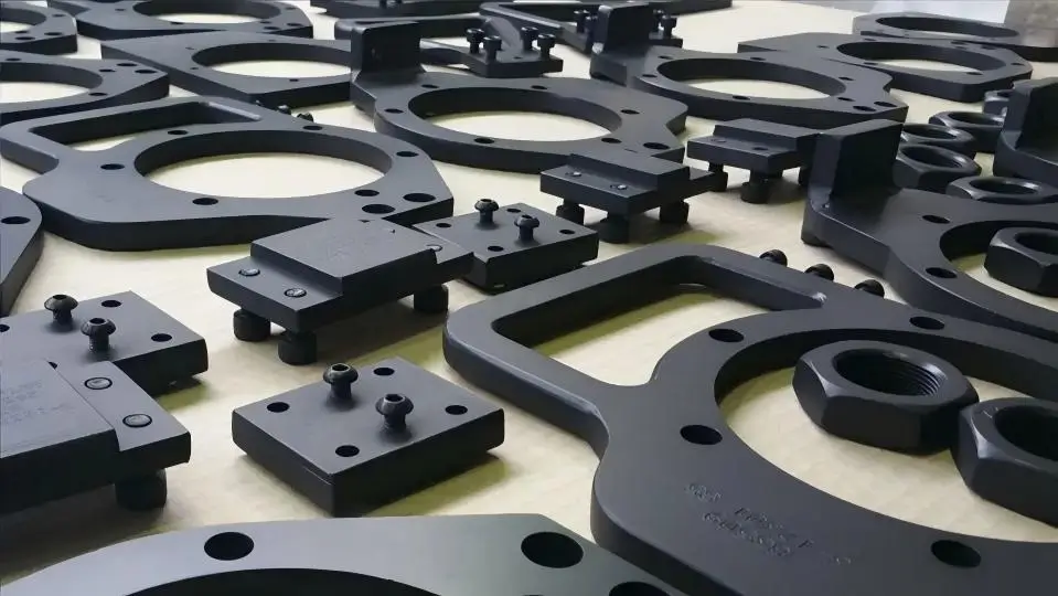
Most UAV structural and control‑critical components are CNC machined rather than molded. These parts operate under vibration, impact, and temperature changes where precision equals performance.
Motor mounts require CNC machining because they endure continuous rotational vibration. Tiny positional errors can cause propeller imbalance and motor bearing wear.
Gimbal brackets rely on planar accuracy and concentric bores so that cameras stabilize correctly. A minor distortion results in visible video shake.
Landing gear joints experience sudden impact loads. CNC aluminum blocks provide consistent grain structure and strength distribution, preventing fracture at stress points.
Avionics housings demand both dimensional precision and efficient heat dissipation. Machined aluminum offers controlled wall thickness and superior thermal conductivity compared to molded plastics.
These parts usually require tolerance‑controlled machining and consistent material properties to ensure structural stability and predictable flight performance.
Most UAV structural and control‑critical components are CNC machined rather than molded. These parts operate under vibration, impact, and temperature changes where precision equals performance.
These parts usually require tolerance‑controlled machining and consistent material properties to ensure structural stability and predictable flight performance.
UAV components often require tighter tolerances than general industrial parts because flight dynamics magnify any geometric imperfection.
Typical benchmarks include alignment surfaces within ±0.01 mm, rotating interfaces with concentricity below 0.02 mm, and flatness on camera mounting plates within 0.02–0.03 mm after finishing.
Threaded inserts, bearing seats, and arm interfaces all demand similar precision to ensure smooth assembly and silent operation.
Such tolerances are crucial because physical misalignment translates directly into flight instability. A tilted motor mount produces thrust asymmetry and vibration that degrades IMU accuracy.
Uneven load distribution along the frame accelerates motor wear and shortens bearing life. Twisted or warped structural parts shift the center of gravity, forcing the control system to constantly correct orientation—wasting power and reducing flight time. In aerial imaging drones, even a 0.02 mm error at the gimbal base can lead to visible horizon drift.
Sharing tolerance expectations early with your machining supplier helps prevent costly redesigns or rework after surface anodizing, ensuring final assembly precision matches design intent.
UAVs operate in constantly changing outdoor environments—exposed to humidity, dust, salt air, and temperature fluctuation.
For this reason, surface finishing on aluminum parts is not an aesthetic option but a functional requirement.
Open‑frame drones, payload mounts, and propulsion housings all face condensation cycles and UV exposure that rapidly oxidize bare aluminum.
Without a protective layer, even minor corrosion can degrade dimensional accuracy or add unwanted surface friction to moving assemblies.
The anodized surface directly addresses these operational stresses through three core benefits: corrosion resistance, electrical insulation, and surface hardness.
In coastal or marine‑survey drones, anodized protection prevents salt‑induced pitting and discoloration that would otherwise compromise joint integrity.
For UAVs carrying sensors or RF modules, the oxide layer’s insulating property minimizes interference and helps maintain clean signal performance—especially around EMI‑sensitive circuits.
And in gimbal mounts or arm joints, the micro‑hard anodized surface dramatically improves wear resistance, keeping fastening points tight over repeated flight cycles.
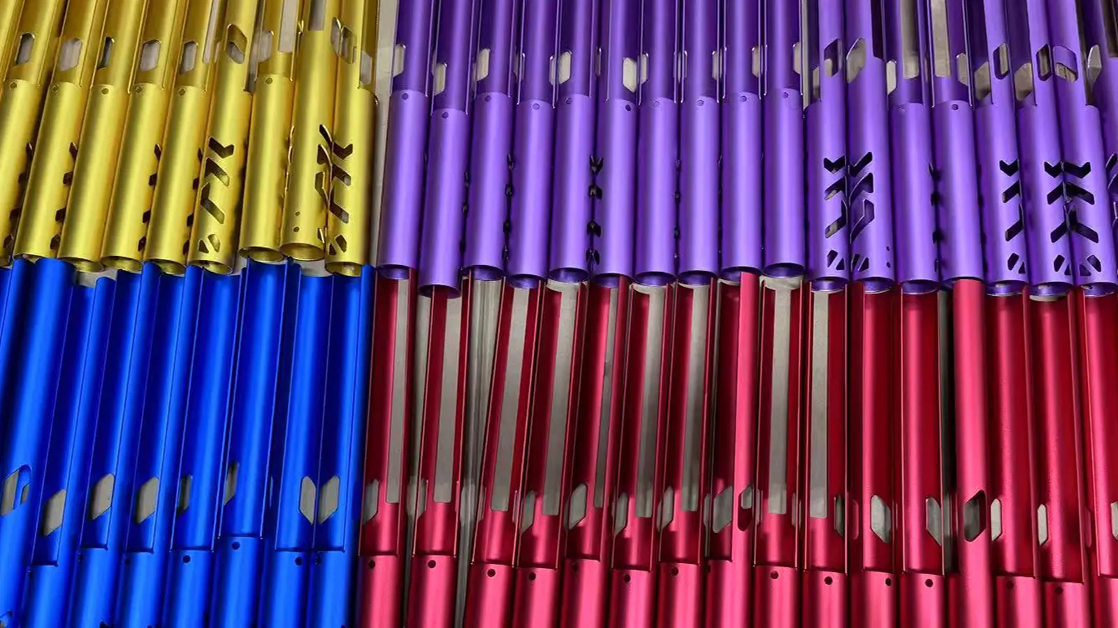
When comparing paint, anodizing, and plating, anodizing strikes the best balance for UAV applications.
Paint adds unnecessary weight and can chip under vibration or exposure, while plating increases density and risks uneven thickness on complex geometries.
Anodizing, however, forms a uniform oxide layer integral to the aluminum itself—lightweight, consistent, and long‑lasting.
The finish can also be dyed and sealed for color coding or branding without compromising performance.
For UAV aluminum components, anodizing is typically specified during the early design stage to ensure durability, consistency, and compliance with aerospace‑grade environmental standards.
Anodizing offers a unique combination of protective and functional advantages tailored to UAV use cases:
Such results make anodizing a go‑to specification when UAV designers seek a balance of strength, reliability, and lightweight precision.
Not all anodizing types provide the same durability. UAV engineers typically choose between Type II and Type III aluminum anodizing depending on part function and wear exposure.
Type II anodizing delivers decorative protection with a thinner oxide layer, usually 5–15 µm. It gives a smooth, uniform color and basic corrosion resistance suitable for structural housings, frames, and covers.
Type II offers easier dyeing, lower cost, and maintains tight fits on assembly features—ideal for components needing both protection and appearance but limited surface stress.
Type III anodizing (hard anodizing) creates a thicker, denser oxide layer, typically 25–50 µm, providing exceptional hardness and durability.
It withstands friction, temperature variation, and frequent mechanical contact.
Hard anodized surfaces suit wear‑intensive areas such as motor mounts, bearing housings, and tool interfaces, where even microabrasion could affect alignment or vibration levels.
As a selection rule: moving or load‑bearing parts → Type III hard anodize, enclosure or decorative parts → Type II standard anodize.
Adopting this approach during design ensures cost efficiency without sacrificing operational life or flight precision.
UAV parts should be designed for both machining and finishing—not just geometric shape. While 3D models define form and fit, surface finishing can subtly alter dimensions, textures, and even assembly performance. Anodizing, in particular, adds measurable thickness that slightly changes critical clearances.
Sharp edges create current density points that cause uneven oxide buildup, leaving visual streaks or pits.
Deep cavities and blind holes trap electrolytes during anodizing and dyeing, leading to inconsistent color or incomplete sealing.
A design that ignores these effects may meet theoretical CAD tolerances but fail in production reality once coating processes begin.
Considering finishing requirements early prevents costly rework and delivery delays. Common production issues usually stem from design oversight: anodized coatings unintentionally blocking threaded holes; post‑anodize hole diameters shrinking below tolerance and causing assembly interference; or visible color inconsistency across parts with different wall thicknesses.
These defects often appear only after surface treatment—forcing re‑machining, stripping, or full remake.
Specifying masking zones, controlled edge radii, and uniform wall geometry helps the CNC supplier maintain both machining accuracy and anodizing quality.
By treating anodizing as part of the design, not an afterthought, engineers ensure functional consistency across batches and reduce downstream variability. Early DFM review prevents costly redesigns later.
Material choice directly influences machining performance, structural strength, and anodizing result.
Two aluminum alloys dominate UAV production: 6061‑T6 and 7075‑T6.
6061‑T6 offers balanced strength, cost efficiency, and excellent machinability. Its moderate hardness allows smooth cutting, minimal tool wear, and predictable surface roughness.
The alloy’s chemistry also promotes uniformly colored anodized finishes, making it ideal for visible housings and general structural frames.
7075‑T6, on the other hand, delivers nearly twice the tensile strength of 6061—vital in high‑load zones such as arms, motor mounts, or landing gear joints.
However, its higher zinc content can cause slight color variation after anodizing, and machining it requires more rigid setups. The trade‑off is a premium in both material and tooling cost.
Selection logic is straightforward: structural or high‑load components → 7075‑T6, housings and general brackets → 6061‑T6.
This balanced approach keeps manufacturing practical while meeting mechanical and aesthetic requirements.
Anodizing adds thickness to aluminum surfaces, and that additional layer directly affects final dimensions.
Typical oxide buildup ranges from 10–30 µm—half growing outward, half inward. This can slightly tighten bearing fits or reduce clearance in precision assemblies.
For threaded holes and press‑fit joints, masking is usually required to prevent coating accumulation that would otherwise alter functional tolerances.
Designers should compensate for this by assigning pre‑anodize oversize dimensions to critical features.
Bearing seats, mating surfaces, and fastener holes often need explicit allowance in the drawing so the final coated parts meet fit tolerance without post‑adjustment.
Surface roughness should also be planned: smoother machining reduces visible anodizing variation and lowers sealing defects.
By integrating tolerance adjustments and finish planning into design documentation, UAV manufacturers achieve consistent dimensional accuracy after anodizing—saving time, cost, and uncertainty once production moves to scale.
UAV parts require both dimensional and coating inspection to confirm that the finished components meet design intent after machining and anodizing.
Precision geometry alone is not enough—anodizing can subtly alter part dimensions and surface texture.
Quality checks must therefore verify key aspects such as coating thickness uniformity, color consistency, and dimensional retention following surface treatment.
For example, ensuring all mounting holes maintain ±0.01 mm alignment after finishing is just as critical as verifying that the anodized layer stays within the required 20 µm thickness range.
Dual verification is essential because each error stage leads to distinct risks. Excess coating buildup can make tight-tolerance assemblies impossible to fit, damaging bearing seats or fastener threads.
Conversely, uneven anodizing—often due to current imbalance or poor cleaning—creates thin zones prone to corrosion.
Even minor color tone differences between assemblies can indicate inconsistent sealing or dye absorption, suggesting process instability.
By inspecting both machining and finishing, manufacturers ensure functional reliability and visual consistency across production lots.
Comprehensive inspection records—covering geometry, surface roughness, and anodizing parameters—give procurement teams confidence that each production run meets aerospace-grade repeatability.
Inspection reports help validate production consistency and support supplier performance audits over time.
Reliable suppliers use a combination of specialized tools to confirm machining and coating quality:
Together, these methods create traceable inspection data that buyers can review in first-article or batch quality reports.
The most frequent quality issues in anodized UAV parts include color variation, edge burning, and dimensional distortion.
Uneven color occurs when surface preparation or anodizing time varies, leading to inconsistent absorption of dye—especially visible on multi-part assemblies. Edge burning appears as darkened or rough zones where electrical current was concentrated on sharp corners.
Dimensional distortion can result from residual stress release during anodizing or improper masking that allows partial coating buildup in critical holes or joints.
These problems usually stem from insufficient process control, such as inconsistent electrolyte temperature, poor racking setup, or lack of pre-anodize cleaning.
Early supplier audits and first-article inspections can quickly reveal such weaknesses.
By partnering with manufacturers who combine precision CNC machining with disciplined anodizing line management, UAV buyers can avoid rework, improve reliability, and maintain a consistent professional finish across fleets.
In UAV component manufacturing, machining time is typically the biggest cost driver. The more complex the geometry, the longer the toolpaths and coordinate changes required, which increases spindle hours and setup efforts.
Multi‑axis parts such as gimbal mounts or lightweight frames often require several repositioning steps and fixture changes, all adding labor and programming overhead. Tool wear, coolant usage, and precision deburring also factor into total machining time.
Once parts leave the CNC stage, finishing steps such as edge smoothing, cleaning, and pre‑anodizing surface preparation add additional cost per piece.
Anodizing costs vary based on the specified type, batch size, and masking requirements.
Type III (hard) anodizing consumes more electricity, requires longer process time, and involves stricter temperature control, making it more expensive than Type II.
Small batches are inherently costlier per unit because tanks and fixtures must still be set up and cleaned regardless of volume.
Masking areas such as threaded holes or electrical contact points introduces manual handling and inspection, further increasing finishing costs.
Batch production helps reduce per‑part cost through setup amortization and process optimization. Once machining programs and anodizing fixtures are established, repeating cycles improve tool utilization, limit idle changeovers, and stabilize coating parameters.
Consistent orders also allow suppliers to bulk purchase materials and dyes, passing efficiency savings downstream. In short, predictable volume is the strongest lever for lowering unit cost without compromising aerospace‑grade quality.
Several key variables define pricing for CNC‑machined UAV components:
Understanding these drivers allows engineers to interpret quotes transparently and benchmark supplier efficiency.
Prototypes generally cost more per piece because programming, fixture setup, and operator attention are concentrated on a few units.
Machine downtime during first‑article verification and process validation also adds to the effective rate. Even minor design updates require re‑tooling or re‑anodizing, further inflating early‑stage costs.
In contrast, batch production spreads fixed costs—such as setup, fixturing, and scheduling—across many parts. Toolpaths are optimized, cutting speeds adjusted for consistency, and anodizing runs become more stable.
As volume grows, per‑unit cost drops significantly while maintaining traceable quality documentation.
For UAV buyers seeking long‑term supply, requesting quotes for both prototype and mass‑production stages clarifies true cost progression and helps align design revisions with manufacturing efficiency.
Precision, protection, and reliability define every successful UAV component project. CNC machining ensures dimensional accuracy and repeatable geometry across complex assemblies—keeping flight systems balanced and stable.
Anodizing adds durability, corrosion resistance, and professional surface uniformity essential for outdoor operation. And a capable supplier provides the consistency that ties them together, maintaining quality from prototype to scaled production through process control and traceable inspection.
When all three factors align, UAV manufacturers can achieve lightweight structures that perform reliably in demanding conditions, flight after flight.
Whether sourcing motor mounts, gimbal housings, or full airframe sets, choosing suppliers experienced in both machining precision and anodizing control minimizes redesign risk and improves turnaround efficiency.
Send your part drawings with required finish and tolerance to receive a manufacturability review. It’s the most effective way to confirm feasibility, optimize cost, and ensure your UAV components meet performance goals from the very first batch.

5-Axis CNC machining is a manufacturing process that uses computer numerical control systems to operate 5-axis CNC machines capable of moving a cutting tool or a workpiece along five distinct axes simultaneously.

China is the best country for CNC machining service considering cost, precision, logistic and other factors. Statistical data suggests that China emerges as the premier destination for CNC machining.

Selecting the right prototype manufacturing supplier in China is a critical decision that can significantly impact the success of your product development project.

Machining tolerances stand for the precision of manufacturing processes and products. The lower the values of machining tolerances are, the higher the accuracy level would be.