CNC machining of UAV parts with tight tolerance (±0.02–0.05 mm) ensures precise assembly, stability, and flight performance.
Critical components use materials such as 7075-T6 aluminum, Ti6Al4V titanium, or carbon fiber composites.
Design with GD&T, select 5-axis CNC and carbide tools, and apply stepwise cutting with thermal and vibration control to minimize deformation.
In-process inspection using CMM or micrometers confirms compliance, reducing assembly errors and ensuring consistent UAV performance, highlighting CNC machining parts for uav.
CNC Machining Requirements for UAV Parts
CNC machining of UAV parts with tight tolerances (±0.02–0.05 mm) ensures precise assembly, flight stability, and motor alignment. Critical materials include 7075-T6 aluminum, Ti6Al4V titanium, and carbon fiber composites. Minor deviations can cause vibration, misalignment, or frame warping. Tolerance stack-up analysis and CAD simulations predict assembly behavior, reducing errors. Tight tolerances are especially important for motor mounts and load-bearing UAV frame sections, ensuring functional and structural reliability.
The Meaning of Tight Tolerances in CNC UAV Parts
- Definition: In CNC machining, “tight tolerances” typically refer to extremely small allowable dimensional deviations. For critical aluminum components such as UAV frames, industry standards (e.g., ISO 2768-1:2022) require tolerances to be controlled within ±0.02 to ±0.05 mm. This is approximately one-third to one-half the diameter of a human hair and is key to ensuring high interchangeability of parts and assembly accuracy.
- Impact of Small Deviations on UAVs: Minor dimensional deviations can directly affect UAV stability, vibration levels, and flight performance. For example, a slight offset in the motor mounting hole can cause the motor shaft to be misaligned, resulting in abnormal vibrations, reduced motor efficiency, shorter flight time, and seriously affecting flight smoothness and control accuracy. Improper clearance between frame components may also cause extra deformation or noise under stress.
- Practical Advice: Before machining, it is essential to perform a tolerance stack-up analysis on the assembly. A single part may meet tolerance requirements, but errors can accumulate when multiple parts are assembled, potentially causing the final assembly to fail or malfunction. Early analysis helps optimize the tolerance allocation for each part.
Common Materials for High-Precision UAV Parts
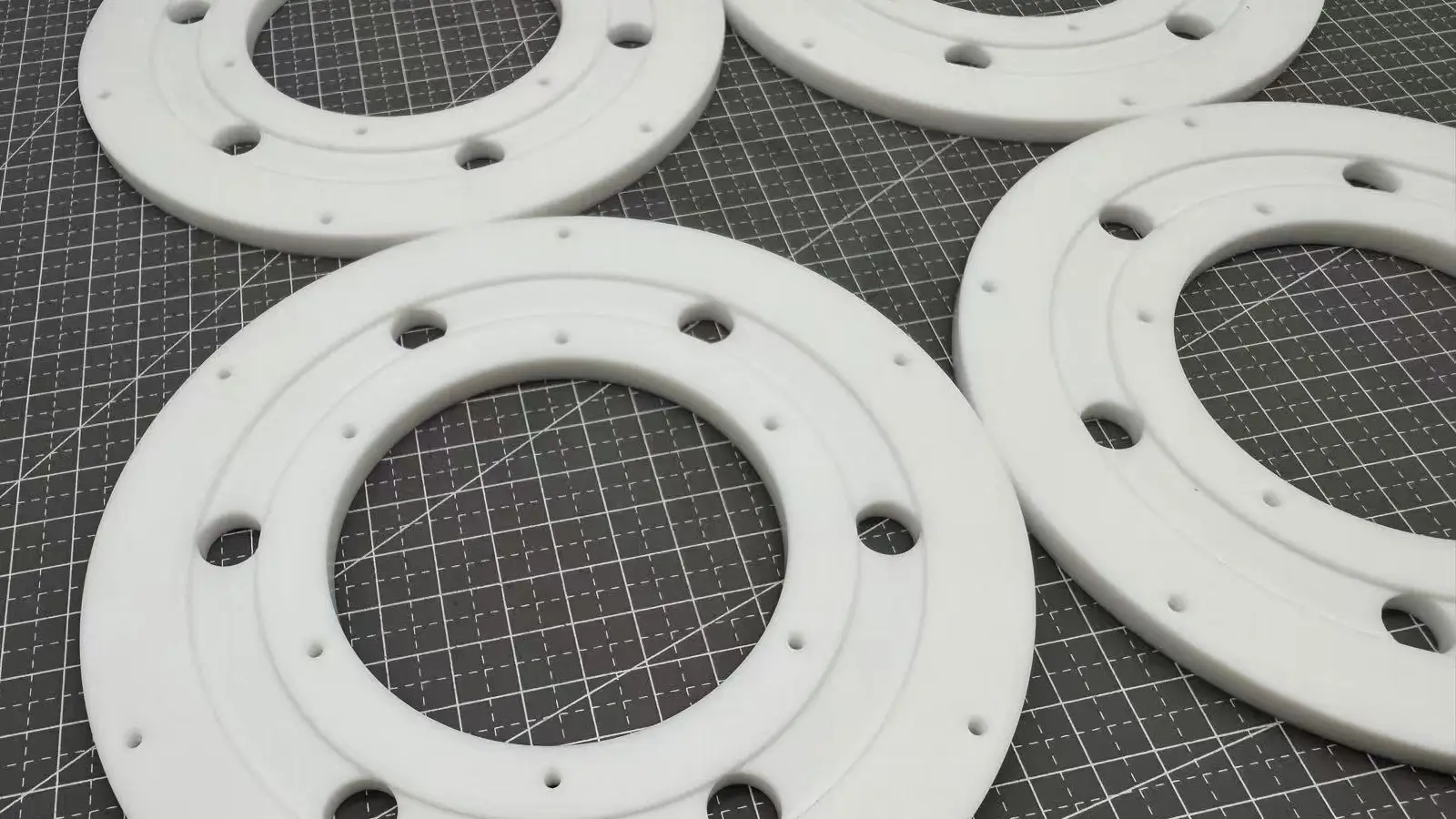
Typical materials include Aluminum Alloys (6061-T6, 7075-T6), Titanium Alloys (Ti6Al4V), and Carbon Fiber Composites, used for lightweight, stiff, or aerodynamic UAV parts. 7075-T6 aluminum can maintain ±0.03 mm tolerance over 200 mm under good CNC conditions. Softer alloys like 6061 reduce tool wear and deformation in complex geometries, making tight tolerances easier to achieve. For deep cavities, thin walls, or fine internal corners, softer alloys reduce cutting force stress and minimize dimensional deviation.
- Main Materials:
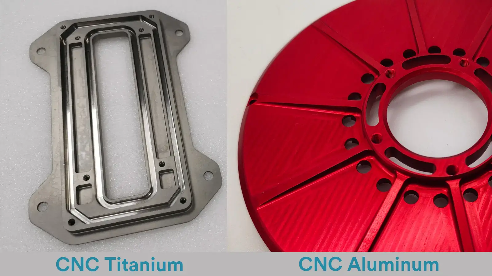
- Aluminum Alloys: 6061-T6 offers good overall performance, easy machining, and lower cost; 7075-T6 has higher strength, suitable for components with strict strength-to-weight ratio requirements.
- Titanium Alloys (e.g., Ti6Al4V): Used in critical areas requiring extreme strength, lightweight, and excellent corrosion resistance, such as landing gear or special connectors in high-end UAVs. However, machining is more difficult and costly.
- Carbon Fiber Composites: Typically in the form of carbon fiber prepreg boards, machined by CNC for cutting and engraving. Used for extremely lightweight, high-stiffness components with specific aerodynamic shapes, such as shells or arms.
- Quantitative Reference: For example, with 7075-T6 aluminum alloy under good CNC machining conditions, a 200 mm long part can usually maintain ±0.03 mm dimensional stability, making it ideal for high-performance UAV main frames.
- Professional Insight: For parts with complex geometries (e.g., deep cavities, thin walls, fine internal corners), it may be preferable to use softer alloys like 6061. This reduces tool wear and minimizes deformation or dimensional deviation caused by excessive cutting forces, making tight tolerances easier to achieve on complex structures.
Why Precision Is Critical for UAV Performance and Safety?
Exceeding 0.05 mm deviation can cause motor misalignment, frame warping, or sensor errors, seriously affecting flight safety.
In 2024, UAV assembly failures were frequently traced to CNC tolerance errors. Using CAD tolerance simulation helps predict assembly risks and reduces trial-and-error costs.
- Direct Consequences of Insufficient Precision: If the dimensional deviation of critical components exceeds 0.05 mm, it may trigger characteristic problems. For example, motor mounting surfaces may not be coplanar, or shafts may not be aligned, causing power imbalance; or frames may develop internal stress after assembly, leading to warping under temperature changes and seriously affecting flight safety.
- Historical Case Reference: Reviewing several UAV assembly failures or early failures in 2024, the root cause often traced back to tolerance control errors in CNC machined frame parts. For instance, flight vibration abnormalities caused by arm connection hole deviations, or flight controller sensor data distortion due to excessive flatness deviation of the central plate.
- Practical Advice: Before production, fully utilize CAD software tolerance simulation and analysis functions. By simulating tolerance ranges in the digital model, one can predict assembly conditions, interference risks, and potential performance impacts under extreme tolerance scenarios. This step greatly reduces physical trial-and-error costs and ensures product reliability and consistency from the design stage.
Step-by-Step Guide to Achieving Tight Tolerance CNC Machining for UAV Parts
Step 1: Design Tolerances for Manufacturability
During design, GD&T annotations define critical dimensions, flatness, parallelism, and concentricity, improving manufacturability and inspection efficiency. Critical mating surfaces require ±0.03 mm, while non-load-bearing areas can relax to ±0.05 mm. Thermal expansion during milling must be simulated, and high-speed cutting controlled to prevent undersized parts. Proper tolerance allocation balances machining cost and UAV performance, reducing assembly interference and enhancing consistency across multiple components.
- Core Method: During the design phase, use CAD software combined with the Geometric Dimensioning & Tolerancing (GD&T) system to precisely specify critical dimensions and geometrical features (such as flatness, parallelism, and concentricity). GD&T defines tolerances based on function and assembly relationships, providing a more scientific approach than simple linear tolerances and facilitating both manufacturing and inspection.
- Recommended Tolerance Values:
- Critical mating surfaces (e.g., motor mounting surfaces, arm joints): Recommended ±0.03 mm to ensure secure and precise alignment between power units and structural parts.
- Non-critical areas (e.g., some external surfaces, non-load-bearing structures): Can be relaxed to ±0.05 mm to balance machining cost and performance requirements.
- Practical Tip: Always simulate thermal expansion of aluminum parts during milling in the design stage. High-speed cutting generates heat that causes local expansion; machining at room temperature without compensation may result in undersized parts or distortion after cooling. Simulation allows prediction and mitigation through coolant control or stepwise machining strategies.
Step 2: Select High-Precision CNC Machines and Cutting Tools
High-precision CNC machining requires 3-axis or 5-axis mills depending on part complexity. 5-axis machines reduce repositioning errors for curved or high-value parts. Carbide end mills and micro-drills maintain dimensional stability and surface finish.Spindle radial runout should remain ≤0.01 mm, with annual calibration to sustain ±0.02 mm accuracy. Selecting appropriate machines and tools minimizes deformation and ensures tight tolerance UAV components meet design specifications consistently.
- Machine Selection:
- 3-axis CNC mills: Suitable for most relatively simple structural parts.
- 5-axis CNC mills: Critical for complex curved surfaces, multi-angle machining, or high-value parts requiring single-setup processing, significantly reducing repositioning errors. Essential for achieving ultra-tight tolerances at the ±0.02 mm level.
- Spindle precision (typically radial runout 0.01 mm) and overall rigidity are fundamental.
- Tool Selection:
- Carbide end mills: Popular for high hardness and wear resistance, maintaining sharpness for dimensional stability.
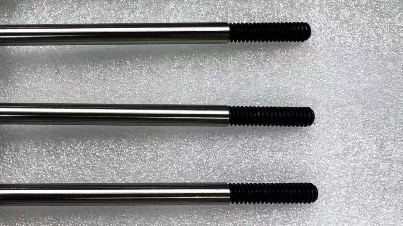
- Micro drills: Used for precision holes <1 mm in diameter (e.g., weight reduction or wiring holes), requiring high rigidity and concentricity.
- Professional Advice:
- Annual Calibration: CNC machines must undergo regular annual maintenance and precision calibration to ensure machining accuracy.
- Spindle Runout Verification: Before every critical machining task, use a micrometer to check spindle radial runout, ensuring it is strictly 0.01 mm, which is crucial for high-quality surface finish and dimensional precision.
Step 3: Adopt Deformation-Minimizing Machining Strategies
Stepwise cutting, soft jaws, and proper fixturing prevent warping in thin-walled or complex UAV parts. Mist cooling controls thermal expansion, while high-speed finishing with shallow cuts reduces residual stress. Aggressive roughing is avoided to prevent internal stress accumulation. Applying these strategies ensures UAV frames maintain ±0.02–0.05 mm tolerances, improving assembly accuracy and overall flight reliability. Experience shows careful cutting and fixture planning reduces post-assembly corrections by over 90%.
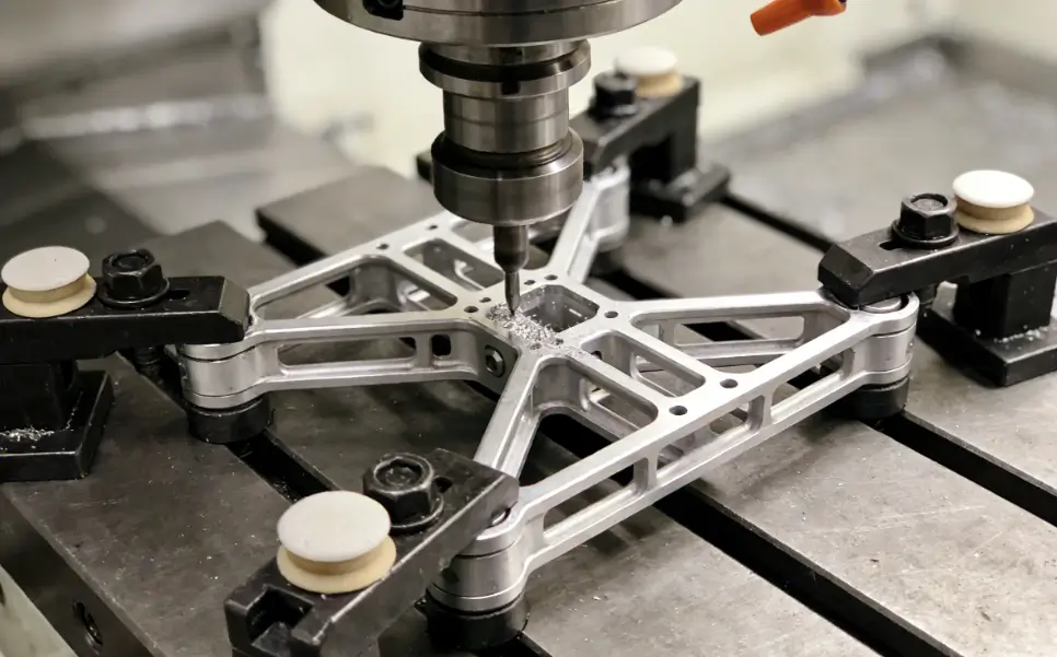
- Clamping Strategy:
- Use soft jaws (machined to match the workpiece shape) or dedicated fixtures to increase contact area and evenly distribute clamping force, preventing surface damage.
- For deep cavities or thin-walled parts, employ stepwise cutting rather than one-pass machining to gradually release internal stress and minimize deformation.
- Cooling Control: Apply continuous mist cooling or minimal lubrication to effectively remove cutting heat, which is key to controlling thermal warping in aluminum and similar materials.
- Insights from Experience:
- High-speed finishing: During final finishing, use high spindle speed, shallow cut depth, and high feed rate for light cutting. This reduces cutting force and heat, lowering residual stress on the part and achieving stable dimensions and superior surface quality.
- Avoid aggressive roughing: Do not use overly aggressive parameters during roughing. Excessive depth or feed creates large cutting forces and heat, embedding stress that may release during finishing or in service, causing deformation.
Step 4: Inspection and Quality Control of Tight Tolerance Parts
Inspection of UAV parts uses CMM, laser scanners, and micrometers to verify dimensional accuracy. Over 95% of critical aluminum components require ±0.03 mm post-machining inspection. Recording all data ensures ISO 9001:2015 compliance and traceability. In-process inspection allows micro-adjustments, preventing cumulative errors in assembly. Consistent application of these quality measures guarantees UAV flight stability, reduces misalignment, and ensures high batch-to-batch reliability, forming a foundation for high-performance UAV production.
- Inspection Tools:
- Coordinate Measuring Machine (CMM): The gold standard for complete dimensional and geometrical tolerance inspection, especially for complex surfaces and spatial dimensions.
- Laser Scanners: Quickly acquire full 3D point cloud data, suitable for free-form surfaces and reverse engineering inspection.
- High-precision micrometers and gauges: Used for rapid inspection of critical hole diameters, thickness, and other simple dimensions.
- Data Reference: Industry data shows that over 95% of core UAV aluminum parts require ±0.03 mm level inspection after machining to ensure batch consistency.
- Professional Advice: Meticulously record all inspection data and results. This ensures not only sorting of qualified parts but also builds a complete quality traceability record. Compliance with quality management systems such as ISO 9001:2015 requires traceability, enabling rapid identification of the processing batch, machine, or even operator in case of issues, facilitating root cause analysis and continuous improvement.
Tips and Best Practices for Ensuring High Precision
Controlling machining environment is essential: maintain 20°C ±2°C and vibration <0.05 mm. Multi-point fixtures and damping pads stabilize lightweight frames. Preheating raw materials for 24 h minimizes dimensional drift. Thermal, vibration, and clamping management directly affect tolerances and surface finish. Applying these best practices reduces errors caused by environmental factors, ensures precision, and supports reliable UAV assembly at the designed ±0.02–0.05 mm tolerance level.
Avoiding Common Errors in CNC UAV Part Manufacturing
- Primary Sources of Errors:
- Thermal Expansion: Material dimensions change due to cutting heat and environmental temperature fluctuations during machining.
- Vibration: Vibrations from the machine, tooling, or clamping system can reduce surface finish and dimensional accuracy.
- Improper Clamping: Poor fixture design or incorrect clamping force can cause part deformation or displacement.
- Quantitative Reference: For aluminum alloys, every 1°C increase in temperature may cause approximately 0.01 mm linear expansion per meter. For precision parts, even small temperature differences can result in dimensional deviations.
- Practical Advice: Before machining, allow raw materials to preheat or stabilize in the workshop environment for at least 24 hours to fully equilibrate with the ambient temperature, effectively reducing dimensional drift caused by temperature differences.
Key Considerations for Temperature, Vibration, and Fixtures
Stable machining environment and proper fixture design are critical for consistent ±0.02 mm tolerances.
- Machining Environment Control:
- Temperature: Ideal machining environment should be maintained at 20°C ±2°C. This is critical for achieving long-term, stable tolerances at the ±0.02 mm level.
- Vibration: Machine foundation and environmental vibrations must be controlled; vibration amplitude in critical equipment areas should be below 0.05 mm. Avoid placing machines near stamping equipment, frequently opened doors, or under overhead crane paths.
- Fixture Design Principles:
- Use multi-point contact support to ensure uniform and stable forces on the part throughout machining.
- For long or thin-walled components, avoid unsupported spans exceeding 50 mm to prevent chatter or deformation under cutting forces.
- Expert Tip: When machining lightweight UAV frames, use dedicated vibration-damping pads or malleable support materials between the part and fixture or under overhanging sections. This effectively absorbs high-frequency vibration, significantly improving machining stability and surface quality.
Case Study: Successful Machining of UAV Frames
In 2025, a UAV manufacturer machined a 250 mm 7075-T6 aluminum frame to ±0.02 mm using multi-step finishing, in-process CMM inspection, and strict equipment maintenance. Misalignment during assembly was reduced by 90%, flight stability improved, and batch consistency achieved. This demonstrates that disciplined machining, inspection, and environmental control are critical to consistently producing high-precision UAV parts and achieving reliable operational performance.
- Background: In 2025, a leading UAV manufacturer needed to machine a 250 mm long 7075-T6 aluminum main frame for a new model, targeting a tolerance of ±0.02 mm.
- Implementation Strategy:
- Multi-step Finishing: Followed a “roughing—semi-finishing—final finishing” process path, scheduling sufficient stress relief time between each step.
- In-Process Inspection: After semi-finishing, used a shop-floor CMM for in-machine measurement of critical dimensions. Machining programs were micro-adjusted based on measurements before final finishing.
- Strict Equipment Maintenance: Executed a comprehensive CNC machine calibration and maintenance program every 6 months to ensure optimal machine condition.
- Results: Using this systematic approach, the company successfully achieved batch production tolerance targets. Misalignment issues during assembly were reduced by over 90%, significantly enhancing flight stability and batch consistency while lowering post-assembly adjustment costs. This case demonstrates the decisive role of process discipline, in-process control, and equipment maintenance in achieving ultra-high precision.
Conclusion
Achieving tight tolerance in UAV CNC parts requires coordinated design, machining, and inspection. Multi-step finishing, careful fixturing, and thermal/vibration control maintain ±0.02–0.05 mm accuracy. Data shows over 95% of critical aluminum components need post-machining inspection. Consistent application of these practices reduces assembly misalignment, enhances flight stability, and ensures reliability, forming the foundation for high-performance UAV production.