Home » Blog » Continuous Feature GD&T

What is Continuous Feature GD&T?

By Lucas Lo

Published: Jul. 21, 2025

Updated: Oct. 04, 2025

Table of Contents

    Continuous feature symbol is an important modifier in Geometric Dimensioning and Tolerancing(GD&T). It makes particular effects on the tolerancing and measuring condition of features.

    Key Points:

    • The Continuous Feature (CF) symbol is a GD&T modifier used to treat several separate, adjacent features as a single, continuous feature for tolerancing and inspection. This ensures that geometric controls (like perpendicularity) and Rule #1 apply to the entire set as one unit.
    • The Continuous Feature is called out on engineering drawings with the letters “CF” enclosed in a hexagon, placed next to the relevant dimension or in the feature control frame. Extension lines can be used to specify which features are included.
    • The symbol’s application expanded significantly between the ASME Y14.5-2009 and 2018 standards. The 2009 standard restricted its use to “Features of Size” (e.g., cylinders), while the 2018 standard extended it to include surfaces (e.g., multiple planar faces), offering more design flexibility.
    • The primary function of the CF symbol is to guarantee that parts with interrupted features will perform as a continuous whole. 

    1. What is Continuous Feature in GD&T?

    This part will explain the definition of continuous feature GD&T and how to show it on engineering drawings.

    1.1. Continuous Feature GD&T Definition

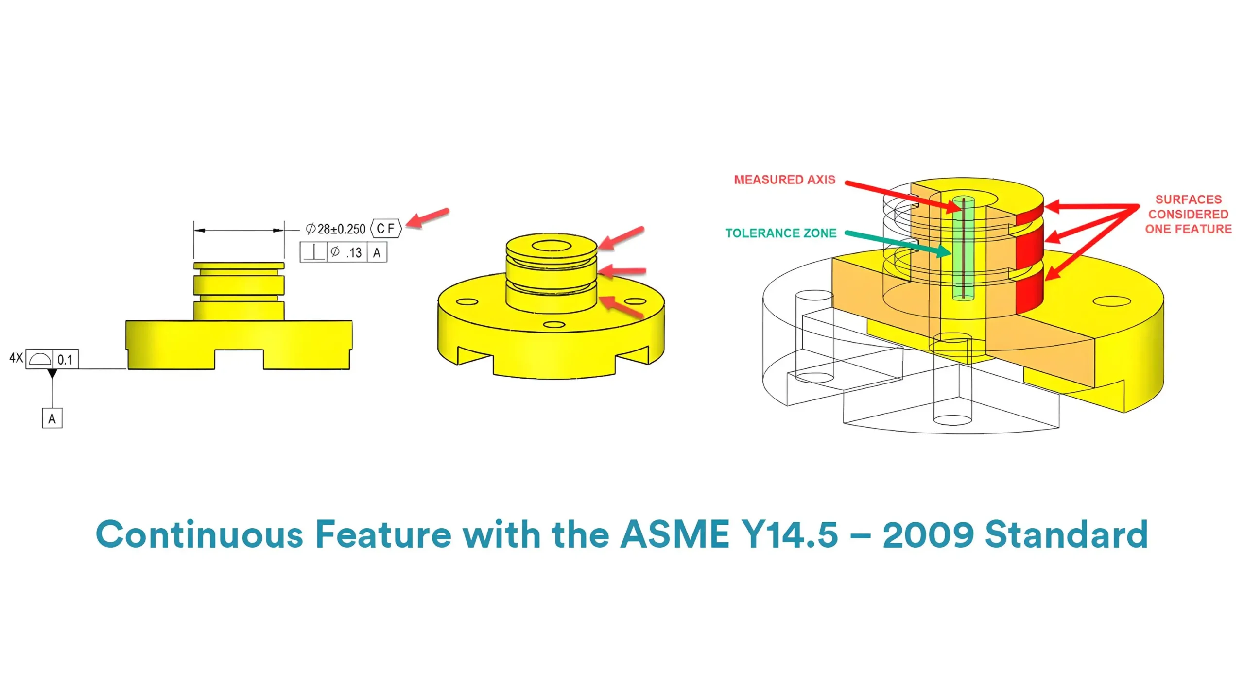
    In Geometric Dimensioning and Tolerancing, continuous feature symbol is a kind of modifier symbol. Continuous feature GD&T is used to indicate that multiple adjacent geometric features should be served as a single continuous feature.

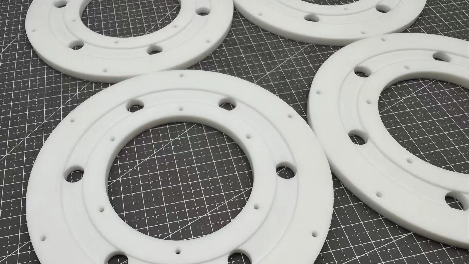
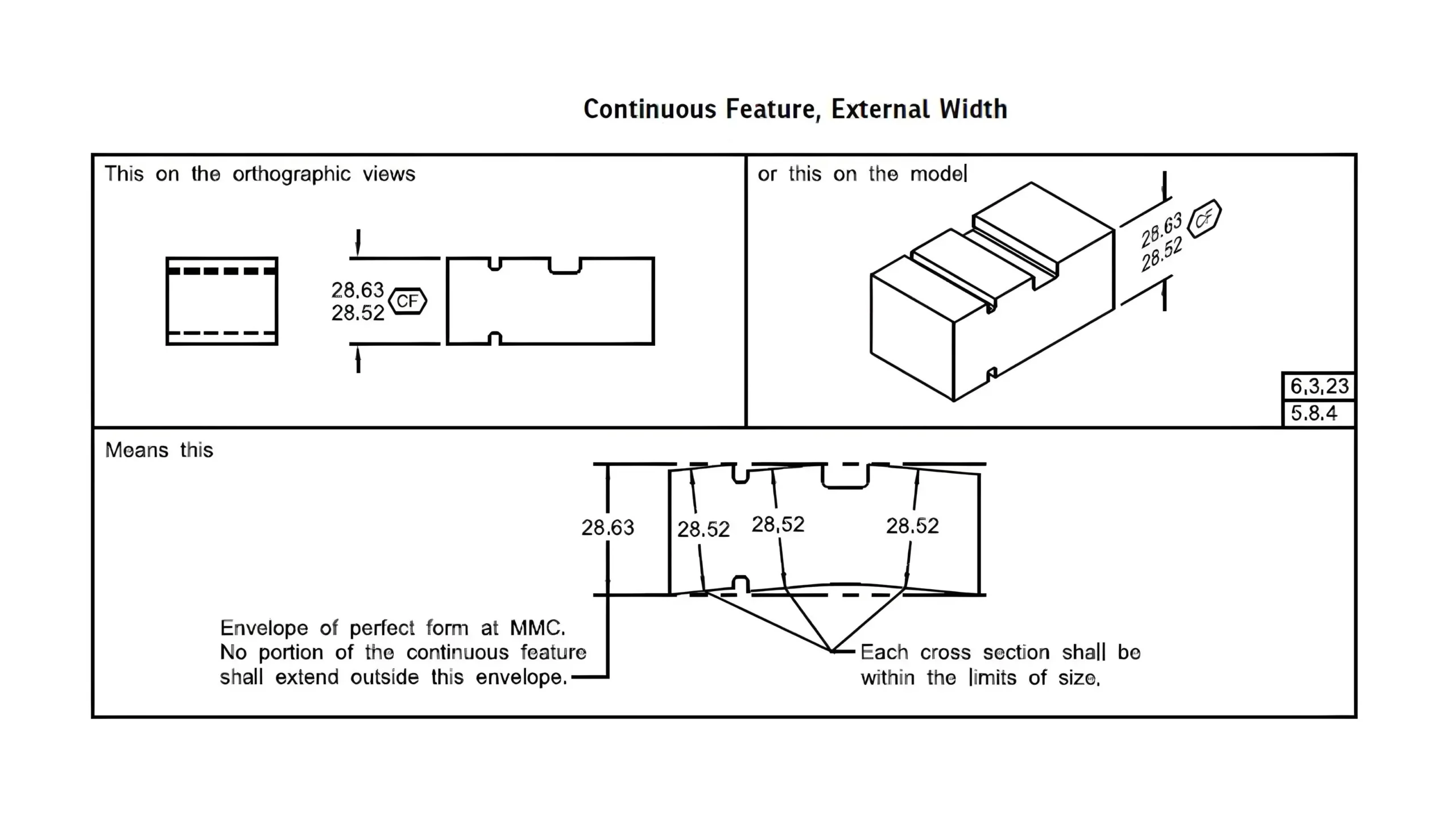
    These adjacent features are disjointed but will be considered as one continuous feature, meaning that they will be controlled as a whole by the Rule #1 or any other geometric tolerances.Continuous Feature GD&T

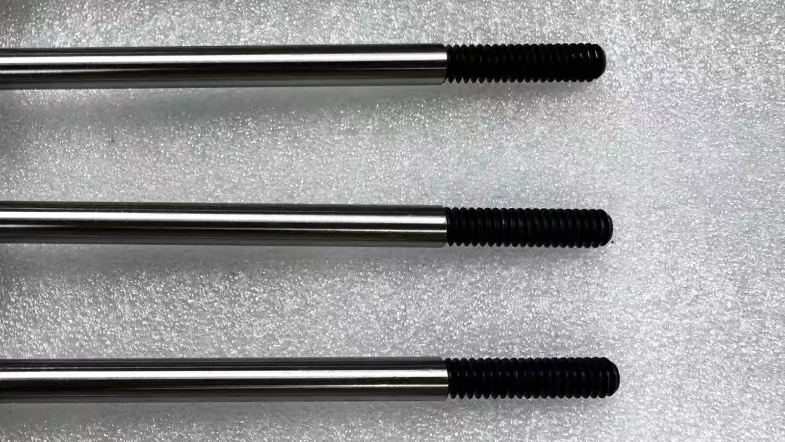
    And these disjointed features are usually within similar geometry, like segmented surfaces or multiple disjointed cylinders.

    1.2. Continuous Feature GD&T Callout

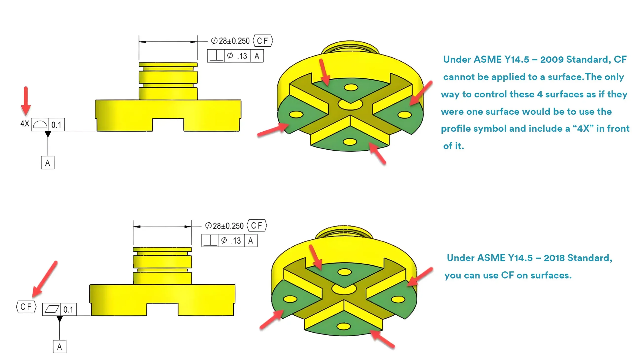
    In Geometric Dimensioning and Tolerancing, if you want to control multiple disjointed features as a whole, the continuous feature symbol should be indicated on the engineering drawing.

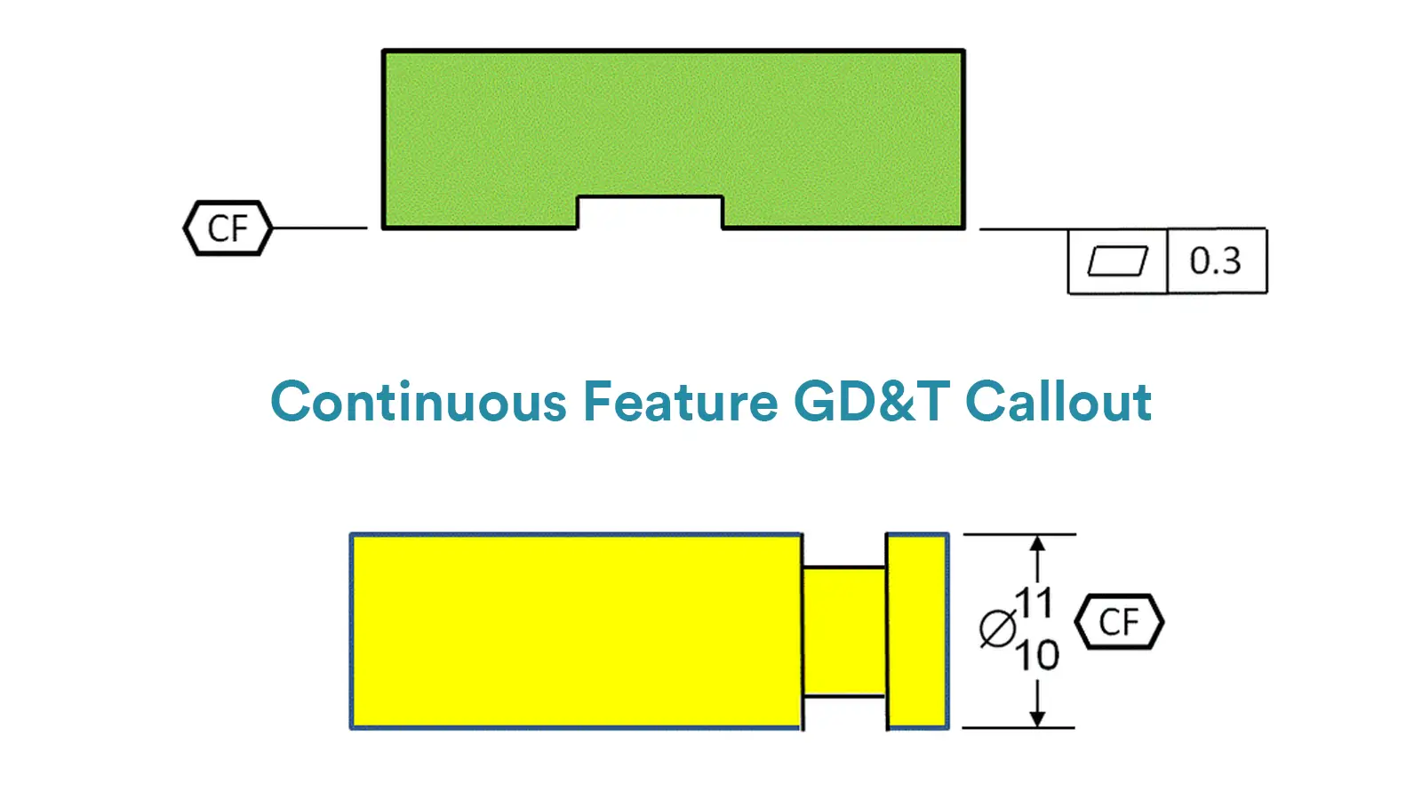
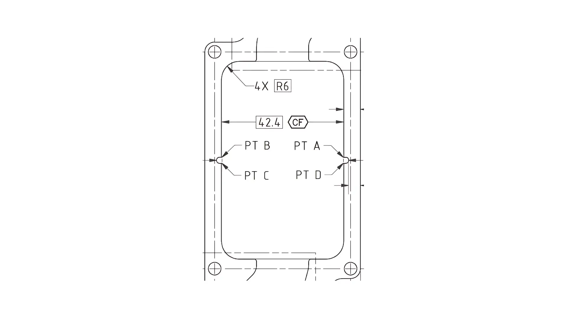
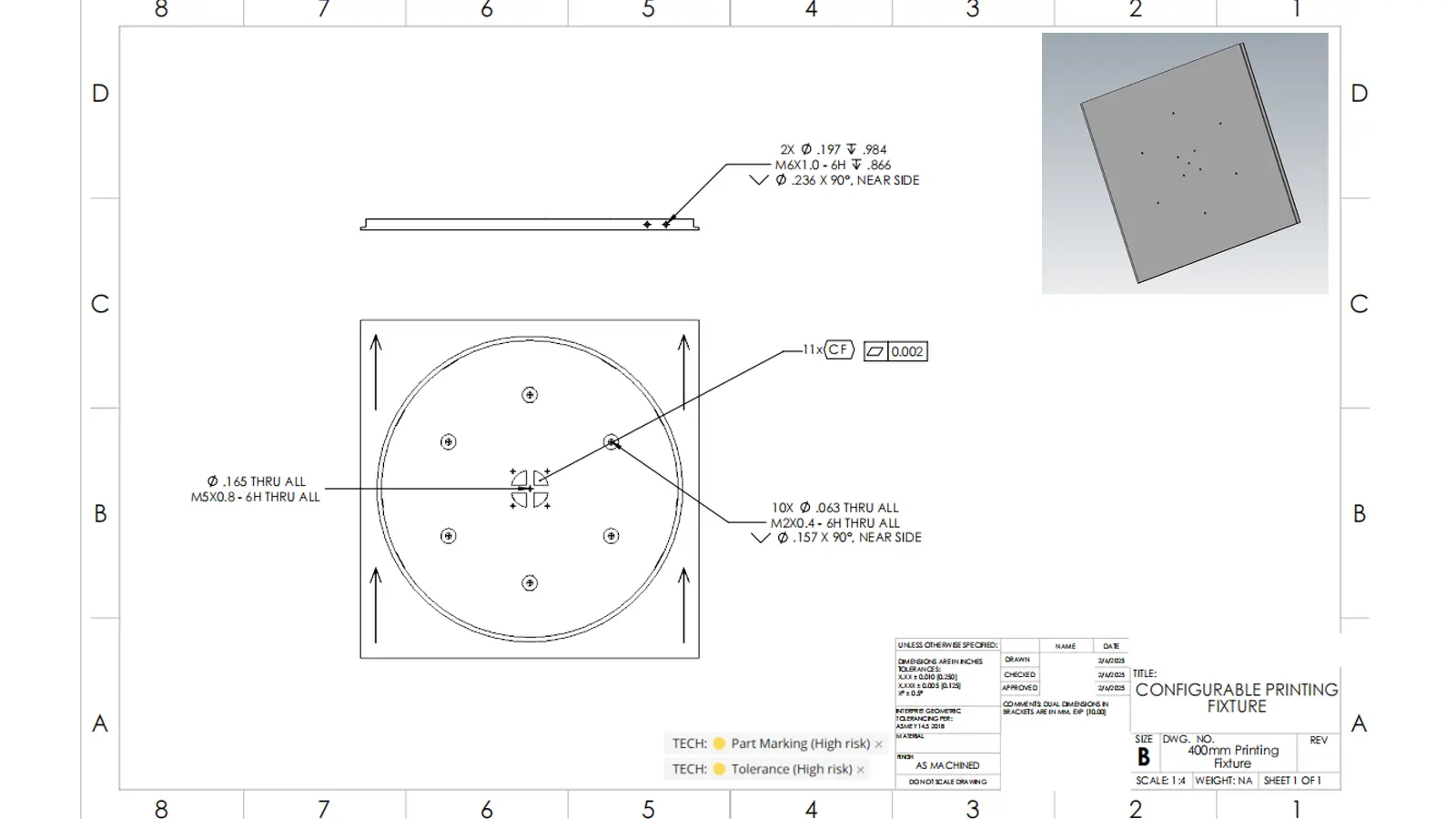
    The symbol of continuous feature is indicated as capital letters “CF” within a hexagon. “CF” refers to the abbreviation of continuous feature.

    And the continuous feature callout is shown through indicating the continuous feature symbol just after the size tolerance.

    2. Continuous Feature under ASME Y14.5-2009 Standard

    The ASME Y14.5-2009 Standard introduces the continuous feature symbol in Geometric Dimensioning and Tolerancing. However, the continuous feature could only be applied to features of size, like holes, shafts, or features within two parallel surfaces.

    This means that under control of continuous feature symbol, those features of size would be controlled as a single whole feature, like the boss apart by the O-ring grooves below.

    If continuous feature symbol is not indicated here, these three cylinders would be allowed to deform in differing directions in form and location within the maximum material condition under Rule #1, or the acceptable tolerance zone under any geometric controls placed on the feature.

    However, when these three cylinders are controlled by the continuous feature symbol, they would be constrained by the Rule #1 as a whole, as if there were no interruption between them.

    And if any additional GD&T Symbol is applied to the feature of size, the GD&T tolerance would be applied to all the three cylinders as if they were one single cylinder. For instant, the perpendicularity symbol indicated above would control the three cylinders as a whole at the same time.

    If required, extension lines can be used to indicate which features of size are under consideration.

    Additionally, please note that the continuous feature symbol cannot be used to a surface according to the ASME Y14.5-2009 Standard.

    The only way to control multiple disjointed surfaces as a whole is applying the GD&T profile symbol on them and indicate a “number X” in front of them. The “number X” refers to the number of those controlled surfaces.

    For instant, the GD&T profile symbol indicated in the below drawing would control the form of the four surfaces at the same time as if they are one single surface.

    3. Continuous Feature under ASME Y14.5-2018 Standard

    Compared with ASME Y14.5-2009 Standard, ASME Y14.5-2018 Standard allows the continuous feature symbol to take both features of size and surfaces under control.

    The continuous feature symbol can be indicated simply within the feature control frame of the controlled surface. It can also be indicated directly next to the datum feature symbol.

    For instant, the four highlighted surfaces on the below drawing would be under control of GD&T flatness symbol as a single continuous planar surface.

    There is no need to indicate “number X” in front of the geometric symbol anymore, but if required, extension lines or “number X” can be used to indicate which surfaces should be controlled as a whole.

    difference for CF under ASME Y14.5 – 2018 Standard and ASME Y14.5 – 2009 Standard

    4. What are Functions of Continuous Feature GD&T?

    There are varieties of crucial functions of continuous feature GD&T in designing and manufacturing.

    • To Ensure Functional Continuity

    It is important to know that although the features under control of continuous feature symbol are physically disjointed, they are usually to function continuously. Continuous feature GD&T plays an essential role in taking the multiple disjointed features under control of geometric or dimensional tolerances as a whole, thus making sure that those features will function continuously and smoothly.

    • To Simplify Tolerance Indication

    Usually, continuous feature GD&T comes into play when multiple disjointed surfaces or features of size of a part are designed to take on the same function, or to ensure the whole profile’s continuity. But indicating the similar tolerance for each single feature would make engineering drawings complicated.

    What’s more, in some cases continuous feature symbol can work as same as some complex composite tolerancing indications, which can convey the designing purpose simpler and avoid misinterpretation to some extent.

    • To Balance Function and Cost

    By making multiple features under control of GD&T Symbols as a whole, continuous feature GD&T can pretend each single feature from excessive control. In addition, multiple features would be measured as a whole but not one by one. Therefore, continuous feature GD&T benefits much on balancing function and cost.

    What is Continuous Feature GD&T
    Continuous Feature in Engineering Drawing Explained

    5. Conclusion

    Continuous feature GD&T is a critical symbol in the design and manufacturing process. It is essential to understand its definition thoroughly and use it accurately.

    Lucas

    Lucas is a technical writer at ECOREPRAP. He has eight years of CNC programming and operating experience, including five-axis programming. He’s a lifelong learner who loves sharing his expertise.

    Learn More about Lucas.

    Other Articles You Might Enjoy

    5 axis CNC machining equipment photo

    What is 5-axis Machining? A Complete Guide.

    5-Axis CNC machining is a manufacturing process that uses computer numerical control systems to operate 5-axis CNC machines capable of moving a cutting tool or a workpiece along five distinct axes simultaneously.

    simultaneous 5 axis machining aluminum

    Which Country is Best for CNC Machining?

    China is the best country for CNC machining service considering cost, precision, logistic and other factors. Statistical data suggests that China emerges as the premier destination for CNC machining.

    5 axis cnc milling machining services

    Top 5 Prototype Manufacturing China

    Selecting the right prototype manufacturing supplier in China is a critical decision that can significantly impact the success of your product development project.

    bladed disks (blisks) check by CMM

    CNC Machining Tolerances Guide

    Machining tolerances stand for the precision of manufacturing processes and products. The lower the values of machining tolerances are, the higher the accuracy level would be.

    Let's get your projects started, together!

    Get custom parts machined in high quality, delivery on time.