In the field of engineering manufacturing, the concept of Controlled Radius(CR) plays a vital role in ensuring the quality and functionality of parts.
This article will systematically introduce the definition of Controlled Radius, engineering drawing callout, application scenarios, machining guidelines, and compare it with related concepts to clear up any confusion that may arise.
A Controlled Radius is a specific type of radius control that requires an arc feature to have a smooth profile with no reverse curvature. It emphasizes the quality and consistency of the arc shape, ensuring that the curvature remains uniform throughout the arc.
This is in contrast to the general concept of Radius, where the Controlled Radius focuses on the smoothness of the contour, which is critical in many precision engineering applications.
It simultaneously guarantees of dimensional accuracy and surface continuity, as opposed to normal radius labeling, which only controls dimensional tolerances.
For example, whereas a normal radius allows for small localized undulations within the tolerance, CR requires that the entire contour must be perfectly rounded.
Ensure the functionality of a part in a precision fit scenario (e.g., hydrodynamic performance, uniform contact stress distribution) by constraining the surface morphology.
The labeling of controlled radii in engineering drawings follows specific rules, requiring integration of arc feature types, dimensional accuracy, datum correlation requirements, and other factors for hierarchical labeling.
The first line is used to indicate the feature type of the arc, the number of arcs, as well as the size and tolerance band:
Symbol: similar to the ordinary radius labeling, for the smooth contour of the arc, labeled as CR. For example, the two-dimensional Controlled Radius arcs directly labeled as CR; in the case of a three-dimensional spherical Controlled Radius surface, it can be labeled as SCR (Spherical Controlled Radius). ·
Quantity: When there are multiple identical Controlled Radius arcs, use “×” to connect the quantity and symbols. For instance, 4 × CR denotes four identical controlled-radius arcs.Basic Size: directly label the radius value and unit, e.g., CR25mm.
Tolerance Labeling: add a tolerance range after the radius value. For example, CR12 ± 0.05mm or CR18mm +0.03/-0.02.
The second line is used for datum correlation and geometric tolerance labeling:
Datum correlation: Datum symbols (e.g., Ⓐ, Ⓑ) are used to denote the positioning reference for arcs.The format is to place the datum symbol after the radius dimension.
For example, CR20mm Ⓐ indicates that a Controlled Radius arc with a radius of 20mm is positioned with datum A as the center.
Geometric Tolerancing: Since the use of CR already emphasizes the requirement for smooth contours, the additional shape control associated with maintaining smoothness may be less commonly used.
However, in some very high precision applications, further geometric tolerance boxes may be added to control other aspects of the arc shape.
Comparison Table of Labeling Examples
Scenario | Annotation Structure | Explanation |
Single 2D arc requiring smooth contour | CR15mm | A 2D controlled radius arc with a radius of 15mm, no tolerance or datum requirement, and a smooth contour |
Multiple spherical features requiring smooth contour | 5×SCR22mm ±0.04mm | Five spherical controlled radius features with a radius of 22mm and a tolerance of ±0.04mm, all with smooth contours |
Arc with datum positioning and smooth contour requirement | CR18mm Ⓑ | A controlled radius arc with a radius of 18mm, positioned centered on datum B, with a smooth contour |
Controlled Radius is widely used in many industries, especially in the field of strict requirements on the surface quality and shape accuracy of parts.
Ensure assembly precision:
By controlling the radii of key parts, such as shaft diameter, bore diameter, gear tooth top circle radius, etc., the precision of the fit between parts, such as clearance fit and interference fit, is ensured, so as to avoid assembly failure due to dimensional deviation.
For example, the engine piston and cylinder radius matching, need to be accurate to the micron level, to ensure the sealing and power transmission efficiency.
Optimize mechanical properties:
Control the radius of transition fillets, such as shoulder fillets and orifice chamfers, to reduce stress concentration and improve the fatigue strength of parts.
For example, if the radius of fillet at the root of gear teeth is too small, it is easy to lead to fracture; reasonably increasing the radius can disperse the load and prolong the service life.
In line with the processing requirements:
according to the processing equipment, such as lathes, milling machines, grinding machines, tool radius characteristics, the design of a reasonable radius of the part characteristics, to avoid processing interference or lack of precision.
For example, when using a milling cutter to process an internal arc, the minimum concave arc radius of the part should be larger than the tool radius, otherwise the processing cannot be completed.
Controlled Radius features are used in many industrial scenarios to enhance part performance:
Aerospace Parts: In the design of aircraft fuselage components and engine parts, control radii are used to ensure smooth airflow around the part, reducing aerodynamic drag and noise. For example, the curvature of an aircraft engine air intake is precisely controlled by the Controlled Radius to optimize air intake and combustion efficiency.
Automotive Design: In automotive body panels and engine components, the application of control radii enhances vehicle aerodynamics and reduces wind resistance. The smooth curves of the body controlled by the Controlled Radius also help improve fuel economy. ·
Medical devices: In medical devices such as surgical instruments and prosthetics, the use of control radii ensures smooth surfaces, which not only facilitates cleaning and sterilization, but also reduces the risk of tissue damage during use.
There are similarities and differences between the concepts of Controlled Radius and ordinary radius, and it is important to understand these for proper application in engineering.
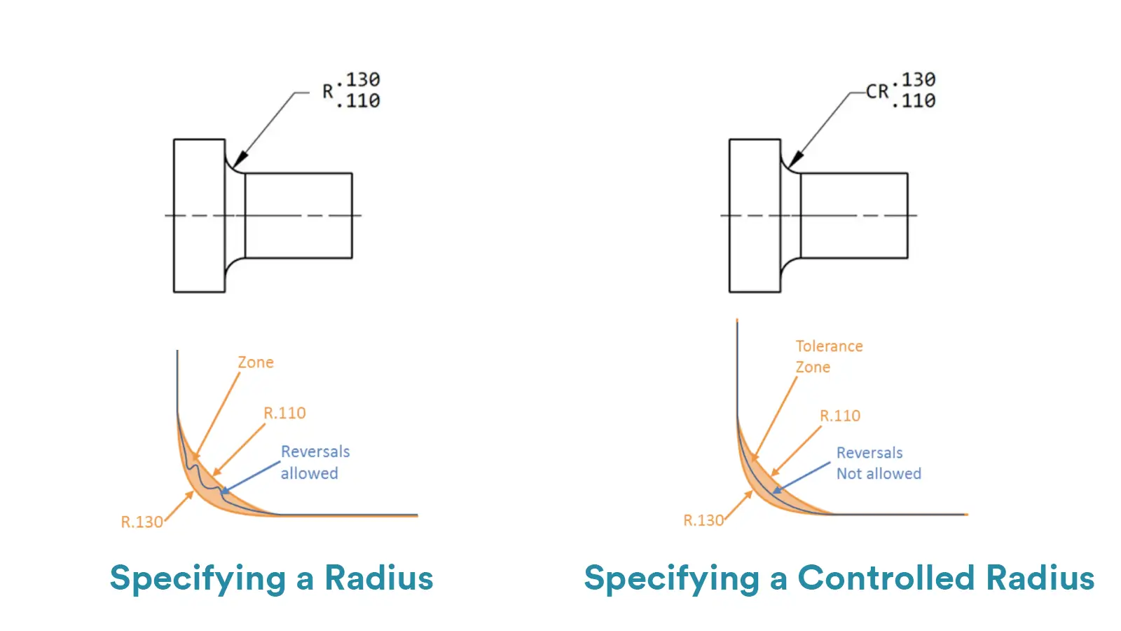
Radius: The distance from a circle’s center to any point on its circumference, a fundamental geometric parameter for circular features. It specifies arc size exclusively, without addressing contour smoothness.
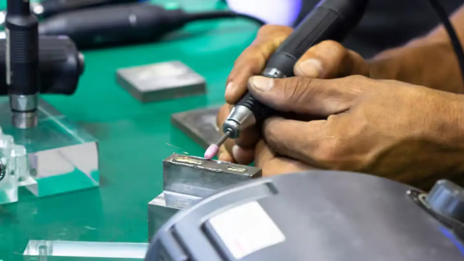
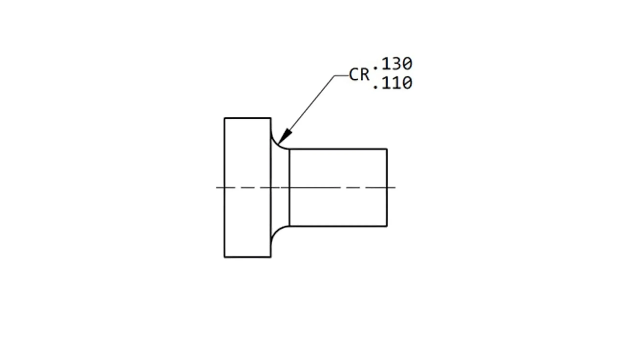
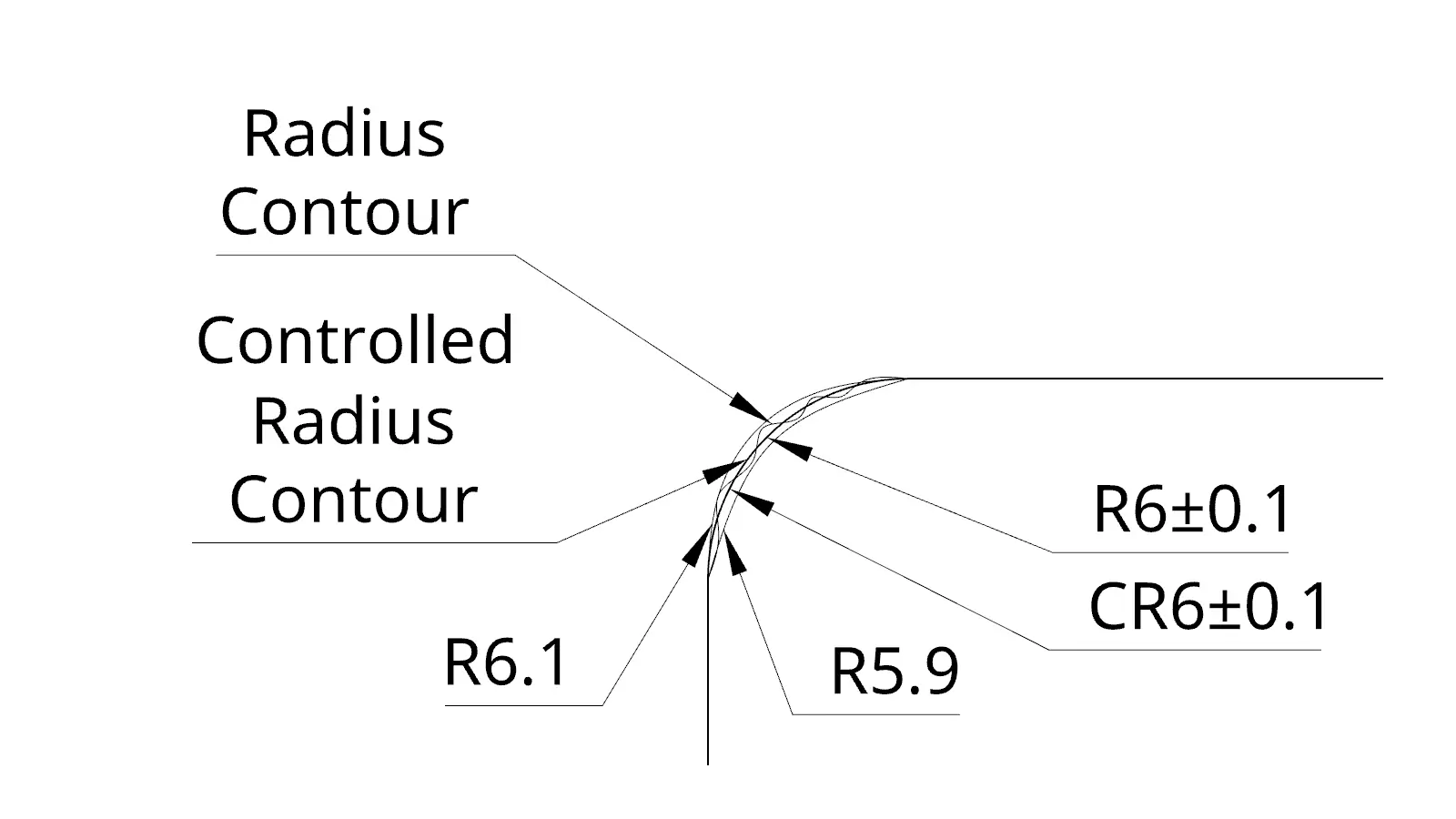
Controlled Radius: focuses on ensuring that the circular feature has a smooth contour with no reverse curvature. In addition to defining the size, it focuses more on the quality and consistency of the arc shape and is used in application scenarios where curvature smoothness is critical.
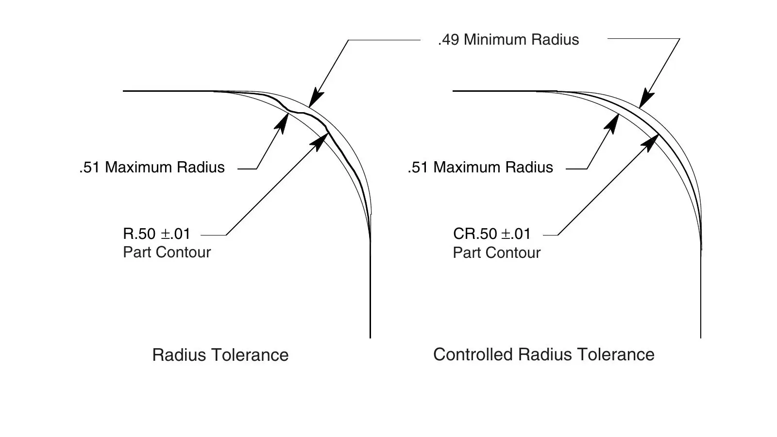
Radius notation: Prefix with “R” for regular radii and “SR” for spherical radii.For example, R20mm denotes an arc with a radius of 20mm and SR30mm denotes a sphere with a radius of 30mm.
Controlled radius notation: Use “CR” as a prefix for controlled radii and “SCR” for spherical controlled radii. For instance, “CR15mm” denotes a 15mm controlled-radius arc, while “SCR25mm” signifies a 25mm spherical controlled radius.
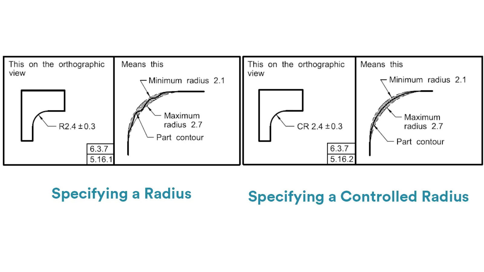
Radius: Widely used in general engineering applications to define the size of circular or spherical features, such as the radius of holes, rounded corners, and the radius of spherical parts. It is mainly used to control the basic geometry and curvature of common parts.
Controlled Radius: Used in scenarios where high precision surface quality and smooth contours are required, such as aerospace, automotive and high-end consumer product design. Used to optimize hydrodynamic performance, improve stress distribution, and enhance the aesthetics and functionality of critical components.
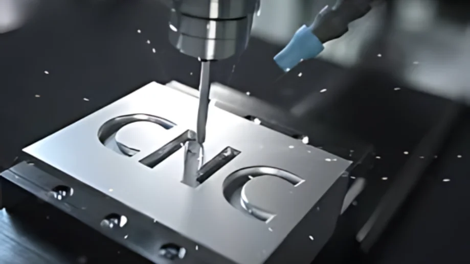
The ordinary fillet radius is a simple inverted circular transition between two surfaces, usually specified by only one radius value (R). It does not necessarily guarantee a smooth profile without reverse curvature.
In some cases, due to a lack of clarity of understanding, the ordinary fillet radius may be misinterpreted as a Controlled Radius. However, whereas normal fillet radius focuses only on the basic dimensions of the inverted rounding transition, Controlled Radius emphasizes the smoothness and quality of the entire contour.
A variable radius is a radius that varies along a curve or surface and is used to create more complex shapes with changing curvature.
The word “radius” in variable radius may be confused with Controlled Radius. Variable radius is concerned with changes in radius values, whereas Controlled Radius is intended to maintain a smooth and consistent profile with fixed or controlled radius values, and they are used for different design and manufacturing requirements.
Controlled Radius is an important concept in engineering and manufacturing. Through standardized markings and precise machining methods, it is able to meet the high-precision requirements for part shape and surface quality in a variety of industries.
By clearly distinguishing between Controlled Radius and related concepts, engineers and manufacturers can perform more accurate design and production, advancing high-end manufacturing and precision engineering.
Lucas is a technical writer at ECOREPRAP. He has eight years of CNC programming and operating experience, including five-axis programming. He also spent three years in CNC engineering, quoting, design, and project management. Lucas holds an associate degree in mold design and has self-taught knowledge in materials science. He’s a lifelong learner who loves sharing his expertise.
Copyright © 2025 Shenzhen ECO Industrial Co.,Ltd. All rights reserved.