Both countersink and counterbore are common terms in CNC machining and these two holes often appear in the CNC machined part designs. Countersink hole and counterbore hole are much similar to each other and are often interchanged in application.
However, they are much different in certain aspects. And in order to use countersink and counterbore correctly, it is important to know their main distinctions clearly. In this article, we will provide a guide on countersink and counterbore.
The primary step to distinguish the difference between the countersink and counterbore is to respectively know what is countersink and what is counterbore. This part will explain the definition of countersink and provide the guide about its callout on engineering drawings.
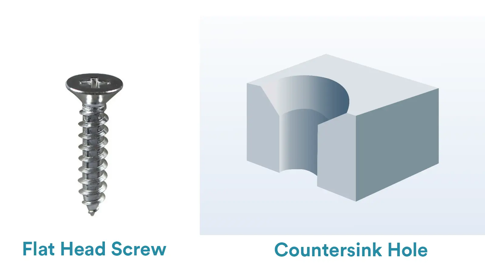
A countersink is a kind of conical recess machined at the head of a cylindrical hole. It allows the head of a screw or bolt to sit flush with or below the surface.
The cone-shaped hole can be machined in any angles from 60° to 120°. And 82° and 90° are most commonly used in CNC machining(82° is applied to ANSI countersink screws while 90° is applied to ISO standard one).
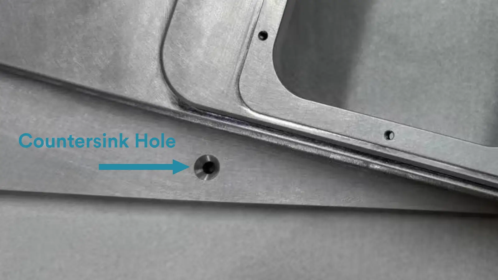
Below is an example of a countersink hole:
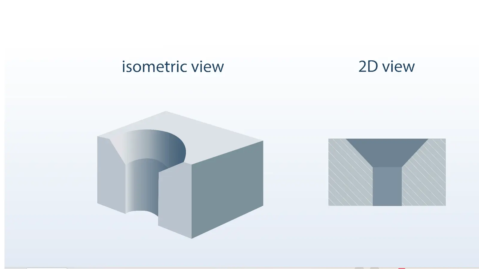
The above example shows the “Major Hole Diameter” of the countersink hole and the specific angle formed with the tapered edges, which is specifically designed based on a specific screw or bolt to be inserted. The angle of the taper above the cylindrical hole is important for fitting and stability.
If the angle is much smaller than that of the fastener, the fastener cannot sink in the hole as deeply and securely as needed. While if the angle is much larger, the fastener would go in at a looser angle and strip the material easily.
The symbol of countersink is an open inverted triangle(“⌵”). It refers to the inverted cone of the countersink. The callout of countersink is mainly composed of two parts(two rows) on CNC drawings.
The first part(the above row) shows the information of the cylindrical hole below the countersink. It indicates the basic dimension of the cylindrical hole(the “Diameter of Primary Hole” shown in the above example) and the hole’s tolerance zone, with a diameter symbol beforehand.
The second part(the bottom row) shows the information of the coned-shaped hole of a countersink.
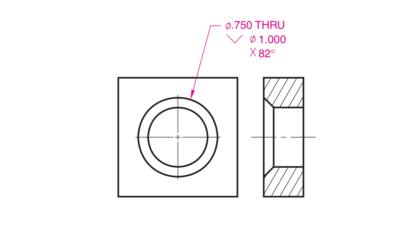
It indicates the symbol of countersink foremost. And then is the diameter symbol and the basic dimension of the countersink hole(the “Major Hole Diameter” shown in the above example) as well as the hole’s tolerance zone. The last one shows the required angle of the countersink.
Then the callout would be connected with a leader arrow that points to the edge of the measured countersink. Below shows an example of the countersink callout:
This part will explain the definition of counterbore and provide the guide about its callout on engineering drawings.
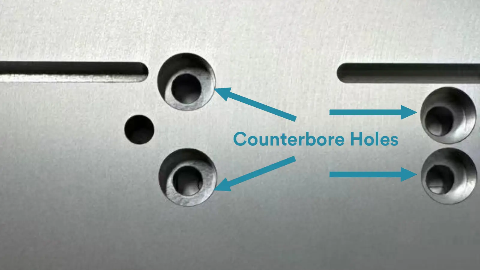
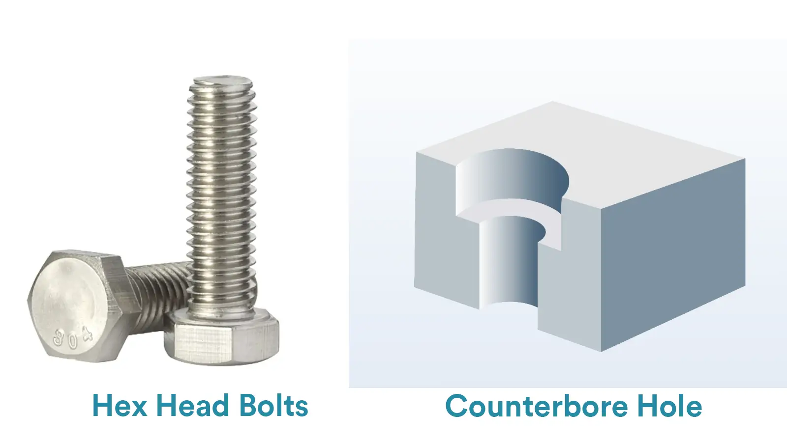
A counterbore is a kind of cylindrical flat-bottomed hole machined at the head of another cylindrical hole(the thru hole).
The counterbore hole and the thru hole is coaxial with each other. And since the counterbore is designed to enlarge the opening of the thru hole, the counterbore’s dimension is usually larger than that of the thru hole.
Compared with the countersink hole, a counterbore hole is a totally cylindrical and straight hole whose walls are 90° perpendicular and bottom is flat.
The larger opening and flat bottom of a counterbore hole provide enough space for fasteners to lie flush or below the level of the material’s surface. And it allows to be used with a lock washer for securer assembly.
Below shows an example of the counterbore hole:
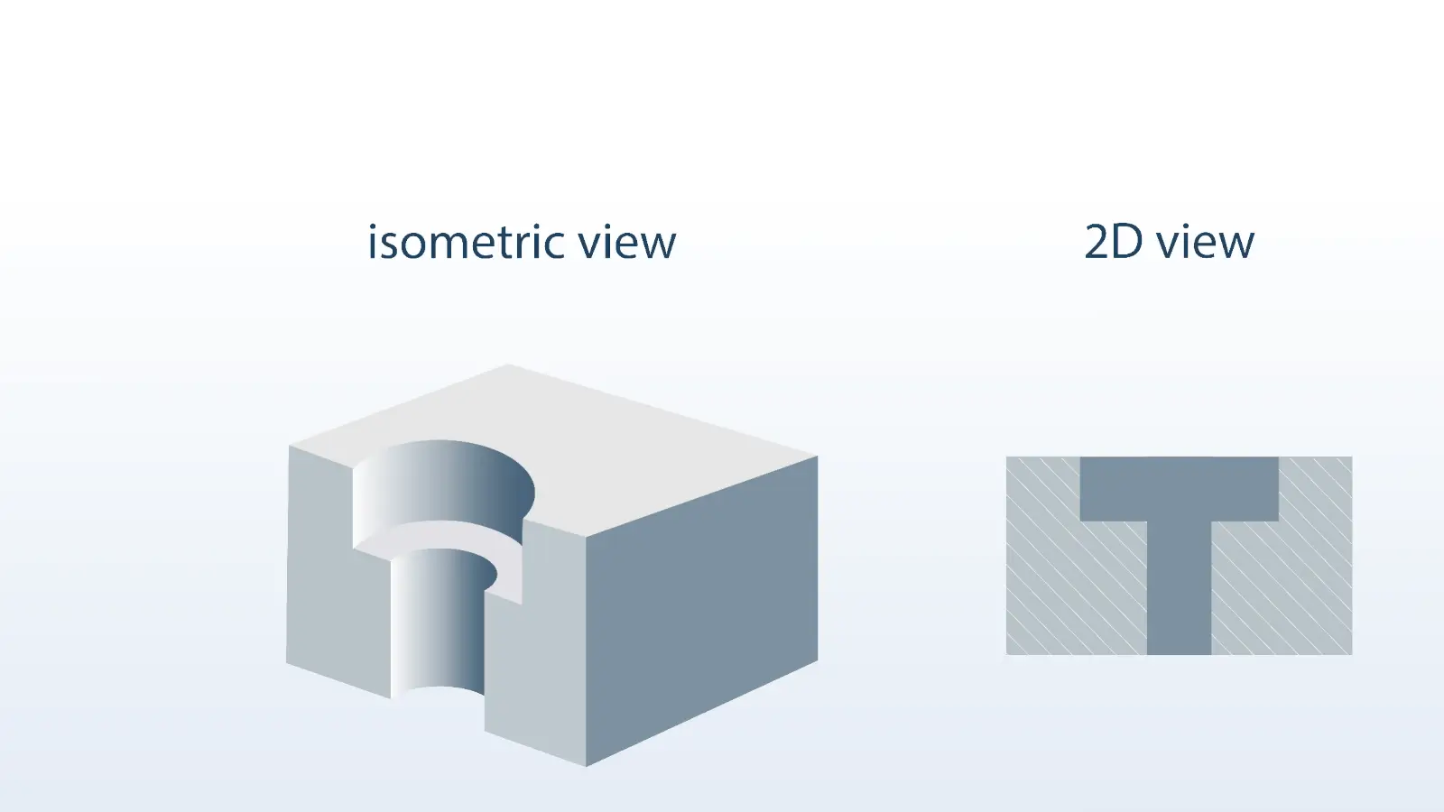
The symbol of the counterbore is the orthographic projection of a counterbore hole(“⌴”), just like a rectangle opening at the top. The callout of counterbore on the CNC drawings consists of two parts.
The first part indicates the permissible dimension zone of the smaller cylindrical hole, with a diameter symbol before.
The second part, shown below the dimensions of the smaller coaxial hole, indicates the information of the counterbore hole. It shows the symbol of the counterbore foremost, following by the diametric dimension of the counterbore with a diameter symbol.
And then shows the dimension zone along the depth of the counterbore hole with a symbol of depth.
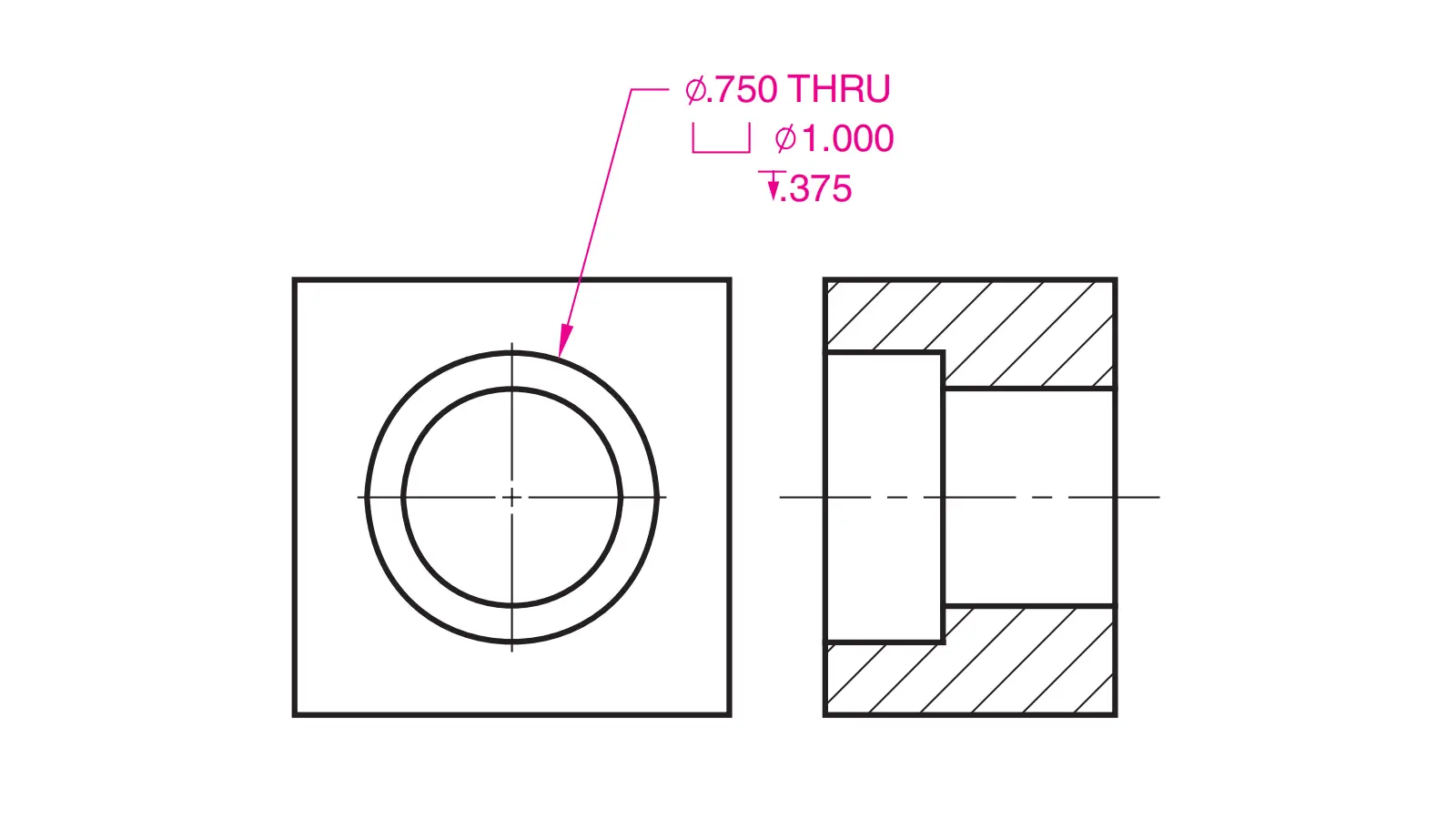
Below shows an example of the counterbore callout:
Though both countersink and counterbore are designed to make fasteners sit flush or below the surface of the machined material, there are various critical differences between them.
It is important to clearly distinguish their key differences. Countersink and counterbore are mainly different from below aspects:
A countersink is an inverted taper hole whose diameter is smaller from the top to the bottom while a counterbore is a cylindrical hole whose walls are completely perpendicular and the bottom is flat.
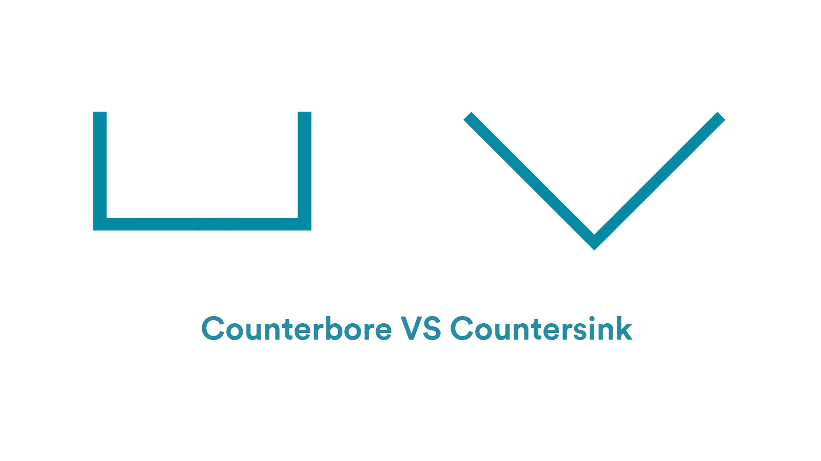
Countersinks are usually smaller than counterbores. Their dimensions are decided by the diameter, depth and angle(for countersinks).
Because a counterbore needs to accommodate the bolt head or nut, while a countersink only needs to match the conical head of the screw(such as a flat-head screw), the diameter of a counterbore is commonly larger than the biggest diameter of a countersink taper.
And because a counterbore needs to provide enough space for a fastener(usually with a lock washer) to completely sink into the material, while a countersink only needs to make a fastener sit exactly flush with the level of the material, the depth size of a counterbore is usually larger than that of a countersink.
Countersinks are primarily machined for countersunk screws whose conical heads match the shape of the recesses. Whereas counterbores are mainly machined for flat-bottom bolts, machine screws, and fasteners with lock washers, such as hex head bolts/screws and socket head cap screws.
Countersinks are used to make fasteners exactly flush with or slightly below the surface of the material, thus to ensure the surface of the material flat and nice.
Countersinks can remove the burr left after the drilling or tapping and can prevent the edge of the material from bearing by the screw head.
Counterbores are used to make fasteners completely sink into the material(leaving certain space), thus to fasten the bolt’s head and provide enough holding strength.
Counterbores usually can take on more holding strength than countersinks do since the force applied on the socket cap screw head is similar to that on the axis and is evenly distributed over a larger surface area.
Countersinks are commonly used on soft and thin material like wood or light metals. The main applications of countersinks include assembly panel, sheet metal parts, aircraft skin and vessel outer shell etc.
Counterbores are commonly used on metal material, especially mechanical components. The main applications of counterbores cover heavy machinery, construction components, and high-accurate machines etc.
In CNC engineering drawings, CSK or C’SINK is the abbreviation for Countersink, and CBORE or C’BORE is the abbreviation for Counterbore.
Though both countersink holes and counterbore holes can make fasteners sit flush pr below the surface of the material, their concrete functions and applications are different.
The main function of countersink holes is to prevent the fastener from sticking out, and thus to provide a smooth and even surface. Besides that, countersink holes also have many various functions. The main situations where a countersink should be used are as follows:
Tapered Fastener: If the fastener is tapered, a countersink should be used. And the countersink angle should be machined to match with the angle of the fastener.
Flushing Surface: If the fastener should sit flush with the surface of the material, a countersink should be used for consideration of aesthetics, interference and safety. Therefore, countersinks are commonly applied on enclosure assembly of electronic products to avoiding scratching customers or influencing appearance.
Soft and Thin Material: If the material you are working on is vary soft or thin, a countersink hole should be used.
Accurate Alignment and Direction: Countersink holes require more accuracy in their hole placement, helping to preliminarily locate the fastener, especially on the curved surface. And their cone-shaped recess is self-centering, making them little difficult to be adjusted and thus play a role on preventing from being tampered.
The main function of a counterbore hole is to make the fastener sink completely into the material and hold high loading. The main situations where a counterbore hole should be used are as follows:
Cylindrical or Hex Fasteners: If the fastener is a socket head cap screw or a hex bolt, a counterbore hole should be used.
Strong Holding Strength: With perpendicular and larger surface, counterbore holes with cylindrical screws can hold more loading force on both radial and axial directions.
Fasteners with Locking Washers: With a flat bottom and a deeper cylindrical hole, a counterbore can provide enough space for a locking washer, which is suitable for vibrating environment like automobile or aviation components.
Accurate Depth: Since counterbore holes are cylindrical, their depth is easier to be controlled. A counterbore hole can be used to control the bolted joint length and to keep the bolt square to the surface.
Due to the different features of countersinks and counterbores, the tools and machining procedure for their manufactures are different.
Step 1: Ascertain the countersink dimension according to the engineering drawing, including the countersink angle, diameter and depth.
Step 2: Choose a proper countersink tool, ensuring the consistency on the angle.
Step 3: Definite the manufacturing program and set the proper coordinate system.
Step 4: Fix the workpiece steadily by the fixing tools and indicate the hole’s center clearly.
Step 5: Align the center of the countersink tool with the hole’s center.
Step 6: Set an appropriate revolutions per minute(RPM) and feed rate, and then start to manufacture a countersink hole, noting to control the drill depth by the Z-axis or a depth stop on the drill press.
Step 7: Remove the countersink tool from the hole and clear any chips out. And clean any rough edges or burrs around the countersink hole down by deburring tool.
Step 1: Ascertain the counterbore dimension indicated on the engineering drawing, including the respective diameters of thru hole and counterbore hole as well as the depth of the counterbore hole.
Step 2: Choose the proper tools for counterbore’s manufacturing. There are two ways. One is to choose the counterbore drill(a kind of special tool that can drill a counterbore at a time). The other is to choose a drill with an endmill to counterbore.
Step 3: Definite the drilling program and set the coordinate system.
Step4: Fix the workpiece steadily on the working platform and indicate the center of the hole clearly.
Step 5: Align the center of the tool with that of the hole.
Step 6: Set a proper RPM and feed rate, and then start to drill the hole. If you choose to use a counterbore drill, you can drill a counterbore hole at a time.
If you choose to use a common drill with an endmill to drill a counterbore hole, you should drill the smaller thru hole first and then switch the endmill to the counterbore bit without moving the workpiece to drill a counterbore hole. Note to control the drill depth.
Step 7: Remove the drill out once the counterbore hole has been manufactured. And then clean any chips out the workpiece.
We have disscussed the differences between counterbore and countersink and below is the table to show them in a summary.
Counterbore vs Countersink: Difference Comparison Table | ||
Item | Counterbore (Flat-Bottom Hole) | Countersink (Conical Tapered Hole) |
Shape | Cylindrical shape with a flat bottom | Conical/tapered shape |
Purpose | Accommodates the head of bolts/screws or nuts so that they are flush with or below the surface | Accommodates flat-head screws so they are flush with the surface |
Matching Fasteners | Hex bolts, socket head cap screws, washers, nuts, etc. | Flat-head screws, countersunk screws, pan-head screws, etc. |
Machining Tools | End mills or specialized counterbore cutters | Conical countersink cutters |
Drawing Symbol | ⌴(A rectangle with a vertical line extending downward) | ⌵ (an inverted triangle) |
Dimension Keywords | Diameter + Depth | Taper angle (e.g., 82°, 90°, 100°) + top diameter or depth |
Typical Applications | Used in mechanical assemblies where bolt heads must sit flush or hidden | Common in applications requiring a clean, flush finish, such as in sheet metal, home appliances, or aerospace panels |
Since countersinks and counterbores are different in various aspects, they serve different purposes and have their own advantages and disadvantages, which decides their own suitable applications.
Simplicity: It is simpler and faster to drill a countersink hole than to drill a counterbore hole.
Lower Cost: The tools for countersink holes are simpler and less expensive. And it takes less time to drill a countersink hole.
Alignment: Countersink holes can help the fasteners to align with the hole automatically.
Weaker Strength: The holding strength of a countersink hole is usually smaller than that of a counterbore because the load is unevenly distributed over a smaller area.
Tight Depth Control: The space for depth variation of a countersink is usually smaller than that of a counterbore.
Stronger Strength: A counterbore hole can provide stronger hold strength than a countersink hole because the load would be evenly distributed on a larger area.
Flexible Depth: The depth of a counterbore can be various to suit with different fasteners and washers.
Various Fasteners: Compared with a countersink hole, a counterbore hole can suit with more kinds of fasteners.
Higher Cost: It usually takes more time and needs more expensive tools to manufacture a counterbore hole.
Material Limit: Commonly, counterbore holes are not suitable for extreme thin material.
Countersink and counterbore holes are two kinds of common holes in CNC machining. Both of them are used to make the fastener sit flush with or below the level of the material surface.
However, they are different from various aspects and respectively have their own advantages and disadvantages. It is critical to clearly know their distinctions before choosing one of them on working. If you still have any confusion with them, please contact with us directly.
Reference 1: Countersink Size Chart for Flat Head Fasteners(ISO)
Fastener Size (Thread) | Pilot Hole Diameter (Close Fit H12) | Pilot Hole Diameter (Normal Fit H13) | Pilot Hole Diameter (Loose Fit H14) | Countersink Diameter | Countersink Angle (°) |
M3 | 3.2 | 3.4 | 3.6 | 6.94 | 90 |
M3.5 | 3.7 | 3.9 | 4.2 | 8.96 | 90 |
M4 | 4.3 | 4.5 | 4.8 | 9.18 | 90 |
M5 | 5.3 | 5.5 | 5.8 | 11.47 | 90 |
M6 | 6.4 | 6.6 | 7 | 13.71 | 90 |
M8 | 8.4 | 9 | 10 | 18.25 | 90 |
M10 | 10.5 | 11 | 12 | 22.73 | 90 |
M12 | 13 | 13.5 | 14.5 | 27.21 | 90 |
M16 | 17 | 17.5 | 18.5 | 33.99 | 90 |
M20 | 21 | 22 | 24 | 40.71 | 90 |
Remark: All dimensions are in millimeter apart from the countersink angle.
Reference 2: Counterbore Size Chart for Socket Cap Head Fasteners(ISO)
Fastener Size | Pilot Hole Diameter (Close Fit H12) | Pilot Hole Diameter (Normal Fit H13) | Pilot Hole Diameter (Loose Fit H14) | Counterbore Diameter | Counterbore Depth |
M1.6 | 1.7 | 1.8 | 2.0 | 3.5 | 1.8 |
M2 | 2.2 | 2.4 | 2.6 | 4.4 | 2.2 |
M2.5 | 2.7 | 2.9 | 3.1 | 5.5 | 3.0 |
M3 | 3.2 | 3.4 | 3.6 | 6.5 | 3.5 |
M4 | 4.3 | 4.5 | 4.8 | 8.0 | 4.8 |
M5 | 5.3 | 5.5 | 5.8 | 10.0 | 5.8 |
M6 | 6.4 | 6.6 | 7.0 | 11.0 | 6.8 |
M8 | 8.4 | 9.0 | 10.0 | 15.0 | 8.8 |
M10 | 10.5 | 11.0 | 12.0 | 18.0 | 10.8 |
M12 | 13.0 | 13.5 | 14.5 | 20.0 | 12.8 |
M16 | 17.0 | 17.5 | 18.5 | 26.0 | 16.8 |
M20 | 21.0 | 22.0 | 24.0 | 33.0 | 21.0 |
M24 | 25.0 | 26.0 | 28.0 | 40.0 | 25.0 |
M30 | 31.0 | 33.0 | 35.0 | 50.0 | 31.0 |
M36 | 37.0 | 39.0 | 42.0 | 58.0 | 37.0 |
M42 | 43.0 | 45.0 | 48.0 | 69.3 | 43.0 |
M48 | 50.0 | 52.0 | 56.0 | 79.2 | 49.0 |
M56 | 58.0 | 62.0 | 66.0 | 92.4 | 57.5 |
M64 | 66.0 | 70.0 | 74.0 | 105.6 | 65.5 |
Remark: All dimensions are in millimeter.
Lucas is a technical writer at ECOREPRAP. He has eight years of CNC programming and operating experience, including five-axis programming. He also spent three years in CNC engineering, quoting, design, and project management. Lucas holds an associate degree in mold design and has self-taught knowledge in materials science. He’s a lifelong learner who loves sharing his expertise.
Copyright © 2025 Shenzhen ECO Industrial Co.,Ltd. All rights reserved.