Depth is an important parameter for describing the spatial position of features in mechanical manufacturing and engineering design, and it is used throughout the whole process from design to processing and inspection of parts.
This article will systematically sort out the core knowledge of depth, including the definition of depth, labeling specifications, common types and measurement methods.Mastery of this knowledge serves as a crucial prerequisite for accurately interpreting engineering drawings and guaranteeing the precision of part feature dimensions.
In this section, we will start from the definition to explain the core meaning of depth as a dimension in the feature space of a part, and then explore its difference with parameters such as length and width.
Depth refers to the vertical distance from a datum or feature surface to another feature surface, usually an internal or recessed feature, and is a key parameter for describing the spatial location of features such as grooves, holes, steps, etc. of a part.
It is widely used in machinery manufacturing, mold design and other fields, for example, in the machining and inspection of features such as mounting grooves in bearing housings, oilway holes in engine blocks, and mold cavities.
In engineering drawings, the depth is usually reflected through a specific labeling, generally marked with an arrow pointing in the direction of the depth measurement, and supplemented with dimensional values and tolerances, providing a clear dimensional basis for the processing and inspection of features.
As an important communication information between design and manufacturing, it clarifies the spatial depth requirements of the feature, ensures the consistent understanding of the feature size of the part during processing and inspection, and guarantees the assembly performance and functional realization of the part.
Depth focuses on describing the distance of the feature along the direction perpendicular to the datum plane, usually for internal or recessed features;
In contrast, length and width typically describe the dimensions of a part or feature in two mutually perpendicular directions within a plane, primarily defining the external contour.
For example, the length and width of a rectangular part refer to the distances between the opposing sides of its base, whereas the depth of a recess on the part is the vertical distance from the top surface to the bottom of the recess.
Hole depth is a specific manifestation of depth, specifically referring to the distance from the mouth of the hole feature to the bottom of the hole;
while the depth of a wider range, in addition to holes, but also includes grooves, steps, cavities, and other features of the vertical distance.
Depth can be categorized into the following 4 categories depending on the type of feature and processing method:
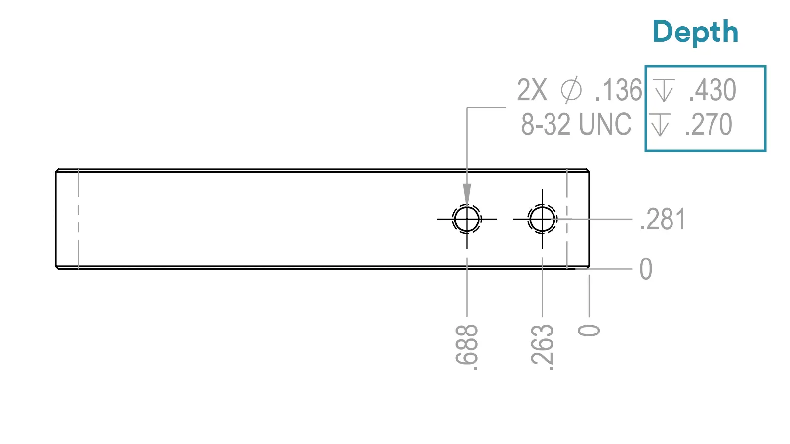
Including through-hole depth, the distance from one end of the orifice to the other end of the orifice and blind hole depth, the distance from the orifice to the bottom of the hole, commonly found in counterbore holes, bolt holes, oil holes, etc.. For example, the depth of a blind hole in a part used for mounting a bolt should be such that the bolt can be screwed in completely and does not exceed the bottom of the hole.
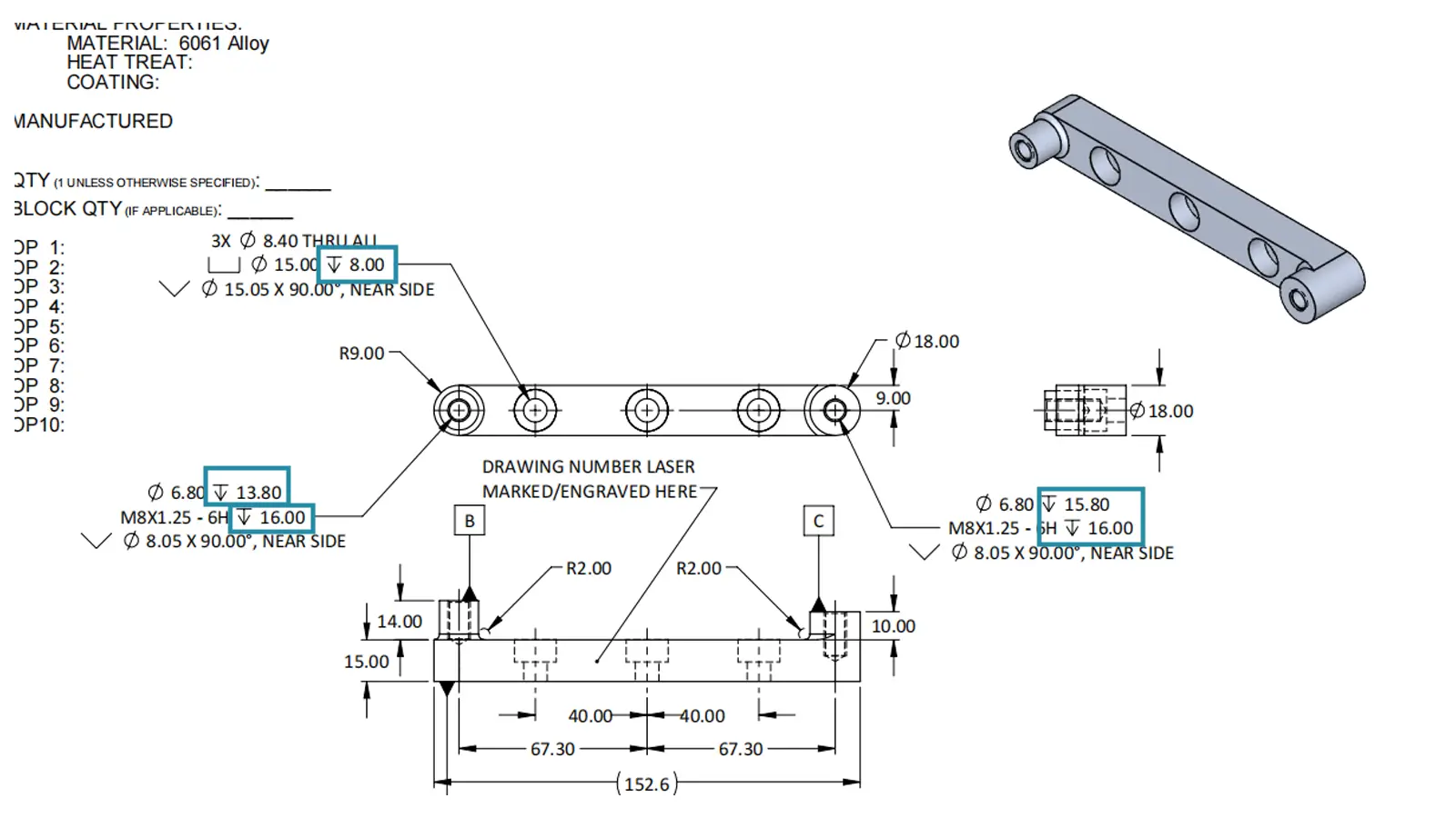
Below drawing shows the counterbore hole depth.
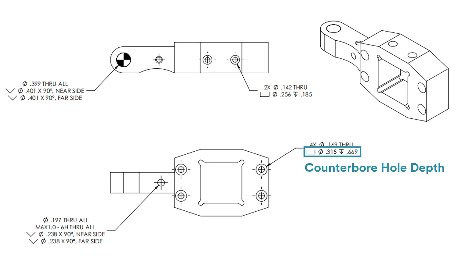
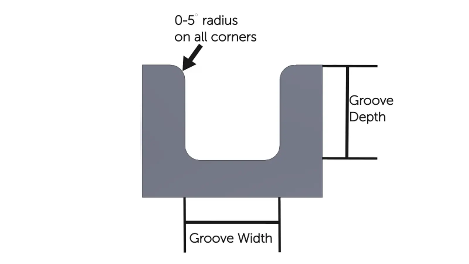
It refers to the depth of a groove feature created by a depression on a part’s surface, including keyways, guideways, and the like. The groove depth should align with that of the key, and specifically, the keyway depth must match the key’s thickness to ensure the key can stably transmit torque.
The vertical distance between step surfaces of different heights on a part, commonly found on shafts and disks. For example, the step depth between different shaft segments on a stepped shaft will affect the axial positioning of the shaft with other parts.
It is mainly present in parts such as molds and boxes, referring to the distance from the open side of the cavity’s inner wall to the cavity bottom. This distance directly determines the space size for molding parts or holding components.
CNC machining offers unparalleled precision and accuracy. Computer-controlled machines can execute complex and delicate designs, minimizing errors and ensuring that every part produced is the same and meets exact specifications.
One of the major advantages of CNC machining is the ability to produce high-volume parts of consistent quality. Once the design and program are set, the machine can produce the same part over and over again without variation, which is vital for industries that demand high standards.
CNC machines run faster than manual machines. They can work continuously around the clock with minimal supervision, which greatly increases productivity, reduces production time, and minimizes human misalignment. This efficiency reduces production costs and speeds up project turnaround times.
CNC machining can handle highly complex designs that are difficult or impossible to achieve with manual machining. The ability of CNC machining to produce complex geometries and fine parts makes it well-suited to the advanced manufacturing needs of the aerospace, automotive, and medical industries.
CNC machining offers a safer working environment compared to manual machining. Operators are not required to be in close proximity to cutting tools and moving parts, which reduces the risk of accidents and injuries. Safety features and enclosures further enhance the protection of workers.
Depending on the shape of the feature and the design requirements, the depth can be labeled in a variety of ways. The following are six common depth labeling methods:
Use the dimension line with an arrow to point to the depth feature, and add the symbol “↓” before the dimension value to clearly indicate the direction of measurement.
For example, “↓15” next to a blind hole indicates that the depth from the datum to the bottom of the hole is 15 mm.
When the depth needs to start with a specific datum, benchmark symbols (e.g., A, B) are associated with the dimensions to ensure uniformity of the measurement datum.
For example, “↓20 A” means that the depth is 20mm with A datum as the starting point.
Label the tolerance directly after the depth value to make clear the accuracy requirements, in the format of “↓ value ± tolerance” or “↓ (upper deviation ± tolerance)” or “↓ (upper deviation ± tolerance)”. “↓ (upper deviation / lower deviation)”.
For example, “↓30±0.02” means that the depth is allowed to be within 29.98mm-30.02mm.
Features such as stepped holes and stepped slots are dimensioned by depth levels, with dimension lines directed to the bottom surface of each step to clearly distinguish between different depths.
For example, stepped holes from the datum, the first layer labeled “↓ 10”, the second layer labeled “↓ 25”, indicating a total depth of 25mm, step difference 15mm.
For multiple features of the same depth, you can mark For multiple features of the same depth, you can label “n × ↓ value” (n is the number), to reduce the repetition of labeling.
For example, “3×↓8” means that the depth of 3 identical features is 8mm.
For complex internal depth features like cavities and blind grooves, the datum plane and the feature’s bottom surface should be connected by a dimension line in the profile, with depth symbols added to intuitively reflect the spatial depth.
Firstly, the datum surface for depth marking must be clearly defined and stable. Typically, critical positioning or assembly surfaces of the part, such as the top and bottom surfaces with high precision, should be selected to ensure the accuracy of depth measurements.
Secondly, the labeling should be clear and intuitive, the depth dimension line should point to the depth direction of the feature, the arrow should clearly indicate the starting point and end point of the measurement, to avoid ambiguity, and to facilitate the processing and inspection personnel to quickly understand.
Again, reasonable labeling tolerances, according to the functional requirements of the feature to determine the depth of the tolerance range, for key features, such as precision fit depth of the step, should be marked with tighter tolerances, non-key features can be appropriately relaxed.
Finally, the labeling should take into account the machining process, for example, for deep hole features, the labeling can be combined with the characteristics of drilling, boring and other processes, to clarify whether it is necessary to reserve machining allowances, or whether it is necessary to mark the depth of the termination, such as flat bottom, rounded bottom.
Depth measurement is the core link to ensure the accuracy of part feature dimensions and assembly reliability. At present, there are 3 commonly used measurement methods, each with unique advantages and applicable scenarios, as shown in the table below.
Method | Description | Recommended Applications |
Depth Gauge | Available in vernier type (accuracy: 0.02mm) and digital type (accuracy: 0.01mm). The reference surface is positioned against the part, and the gauge rod is then extended to make contact with the measured bottom surface for reading. | Medium-depth planar grooves, steps, and blind holes, such as keyways and box steps. |
Depth Micrometer | Accuracy: 0.01mm. The base is positioned against the reference surface, and the thimble is rotated to bring the measuring rod into contact with the bottom.Readings are obtained through scale combination, requiring vertical fitting. | High-precision depth measurement, such as precision mold cavities and high-precision blind holes in engines. |
Coordinate Measuring Machine (CMM) | High-precision automated equipment (micron-level). It calculates depth automatically by establishing a coordinate system through the probe contacting the reference surface and the bottom surface, supporting batch measurement of complex features. | Depth inspection of complex parts, such as automotive irregular grooves and aerospace multi-step features, suitable for high-precision requirements. |
Combination of Plug Gauge and Depth Gauge | The plug gauge verifies the hole diameter; the depth gauge measures the distance from the reference surface to the end of the plug gauge to indirectly obtain the hole depth. | Depth measurement of holes requiring simultaneous diameter verification, such as bolt holes and locating holes. |
Measurements must be taken from a uniform datum.
For non-flat-bottomed structures, the shape of the probe should be considered or a cross-section diagram should be used to assist judgment.
When detecting the probe, pay attention to avoid the error caused by detecting the rounded corner of the hole.
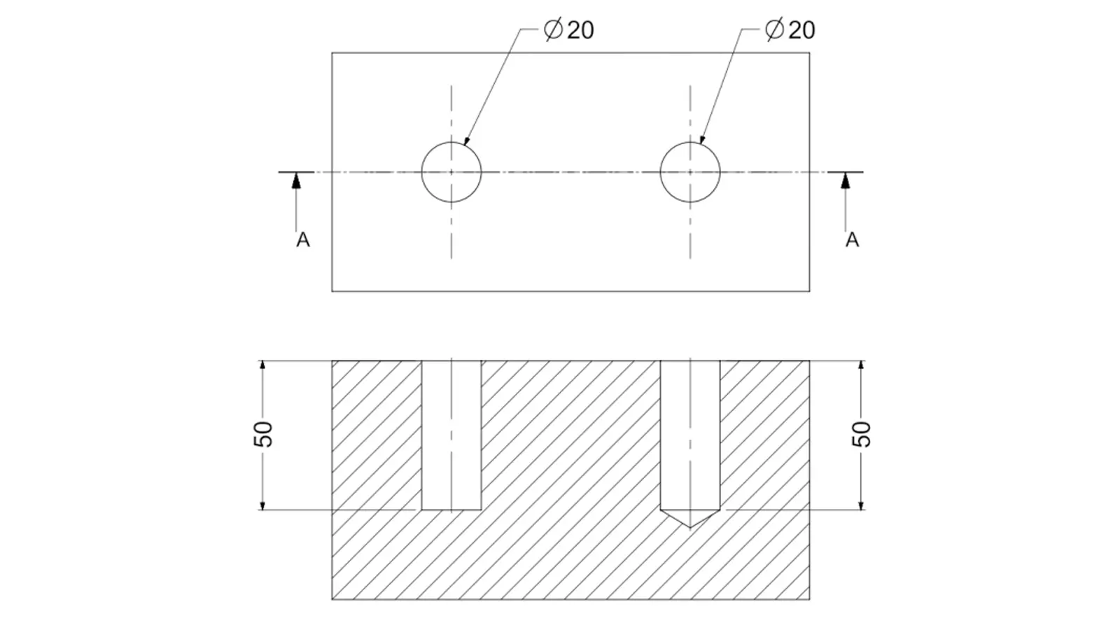
The two holes in the illustration are labeled as 20 diameter and 50 depth, but the cross-section shows that the left hole is flat-bottomed and the right hole is tapered-bottomed. If the structure of the tapered bottom is not clearly labeled, it may lead to measurement errors. The depth of the holes should be determined by combining the profile view with the shape of the probe.
Calculate the upper and lower deviation according to the drawing.
For critical assembly holes, such as positioning pin holes should be controlled within ±0.01mm.
For issues regarding the consistency of multi-hole depths, it is necessary to synchronize program adjustments with tool compensation optimization.
Depth is a key parameter for describing the spatial dimensions of part features in mechanical design and manufacturing.
It is different from flat dimensions such as length and width, and refers specifically to the vertical distance of internal or recessed features, such as holes, slots, steps, etc., relative to the reference plane.
This parameter is used throughout the life cycle of the part, providing a key dimension for machining, assembly and quality inspection.
Lucas is a technical writer at ECOREPRAP. He has eight years of CNC programming and operating experience, including five-axis programming. He also spent three years in CNC engineering, quoting, design, and project management. Lucas holds an associate degree in mold design and has self-taught knowledge in materials science. He’s a lifelong learner who loves sharing his expertise.
Copyright © 2025 Shenzhen ECO Industrial Co.,Ltd. All rights reserved.