Home » Blog » Envelope Requirement GD&T

Envelope Requirement GD&T

By Lucas Lo

Published: Jul. 14, 2025

Updated: Oct. 04, 2025

Table of Contents

    Contrast to GD&T Independency Symbol, Envelope Requirement GD&T stablishes a relationship between size and form, and defines that form is controlled by dimension within a feature’s Maximum Material Condition(MMC).

    It plays a significant role in Geometric Dimensioning and Tolerancing(GD&T). Engineers and manufacturers are required to learn it.

    Key Takeaways:

    • The Envelope Requirement (ASME’s Rule #1) establishes that a feature of size must have perfect geometric form when it is at its Maximum Material Condition (MMC—largest pin or smallest hole). As the feature’s size moves away from MMC, its form is allowed to deviate, but it must never exceed the virtual boundary of perfect form at MMC.
    • A key difference between ASME and ISO standards is how the Envelope Requirement is indicated. In ASME Y14.5, it is the default rule (Rule #1) and requires no symbol. In ISO standards, it must be explicitly called out using the circled ‘E’ symbol (Ⓔ) after the dimensional tolerance.
    • While both involve MMC, the Envelope Requirement and the MMC modifier are distinct. The Envelope Requirement is a default form control linked to the size tolerance. The MMC modifier is used with a geometric tolerance to grant a bonus tolerance as the feature’s size departs from MMC.
    • The Envelope Requirement and the Principle of Independency are mutually exclusive. Independency (symbol ‘I’ in ASME) explicitly separates size and form control, allowing more form variation. The Envelope Requirement links them, ensuring tighter form control for mating features.

    1. What is Envelope Requirement GD&T?

    In Geometric Dimensioning and Tolerancing(GD&T), the envelope requirement defines that the form of a feature of size is controlled by its limits of size. Just as its name suggests, the acceptable deviation of the form of a feature of size is limited by the perfect virtual boundary at the part’s Maximum Material Condition(MMC).

    For further explanation, a feature of size must be of perfect form when it is at its Maximum Material Condition, and as the feature deviates from Maximum Material Condition towards Least Material Condition(LMC), the acceptable deviation of the form is allowed to be larger.

    But note that the real feature must not exceed the geometrical ideal envelope with the maximum material condition within the tolerance zone.

    The envelope requirement GD&T is usually applied to a single feature of size, such as a cylindrical surface or a feature established by two parallel flat surfaces. And it is used for features which are of important for mating parts.

    The envelope requirement ensures that if two parts with features of size are assembled, and both are at their worst acceptable condition(MMC), they will still fit together without interference.

    More importantly, attention to that form can also be refined further by using any of the GD&T Form Symbols, such as GD&T Flatness, GD&T Straightness, GD&T Circularity and GD&T Cylindricity. And the form tolerance must be tighter than that is controlled by the size tolerance.

    Envelope Requirement GD&T

    2. How to Show Envelope Requirement GD&T on Engineering Drawings?

    As we all know, ASME and ISO are two popular international standard systems for engineering and manufacturing. And there would be some distinctions between them, even for the same concept, for instant the envelope requirement GD&T.

    In ASME Y 14.5 Standards, the envelope requirement is implicit and is served as the default rule, meaning that no specific symbol is required. The envelope requirement is particular named as the Rule #1 or Envelope Principle.

    While in ISO Standards, there is a specific symbol used to indicate the envelope requirement. The symbol is a capital “E” within a circle(E). This means that if you want to define that the form of features of size is dependent of their dimension, you should indicate the envelope requirement symbol(E) on engineering drawings when using ISO Standards.

    And the envelope requirement symbol is placed just after the dimension tolerance. What’s more, according to ISO Standards, the envelope requirement can also be applied to an entire drawing by stating it in a general note or title block.

    3. Drawing Examples of Envelope Requirement GD&T

    This part will provide some specific drawing examples of envelope requirement GD&T for detailed and concrete explanation.

    Envelope Requirement GD&T Explained

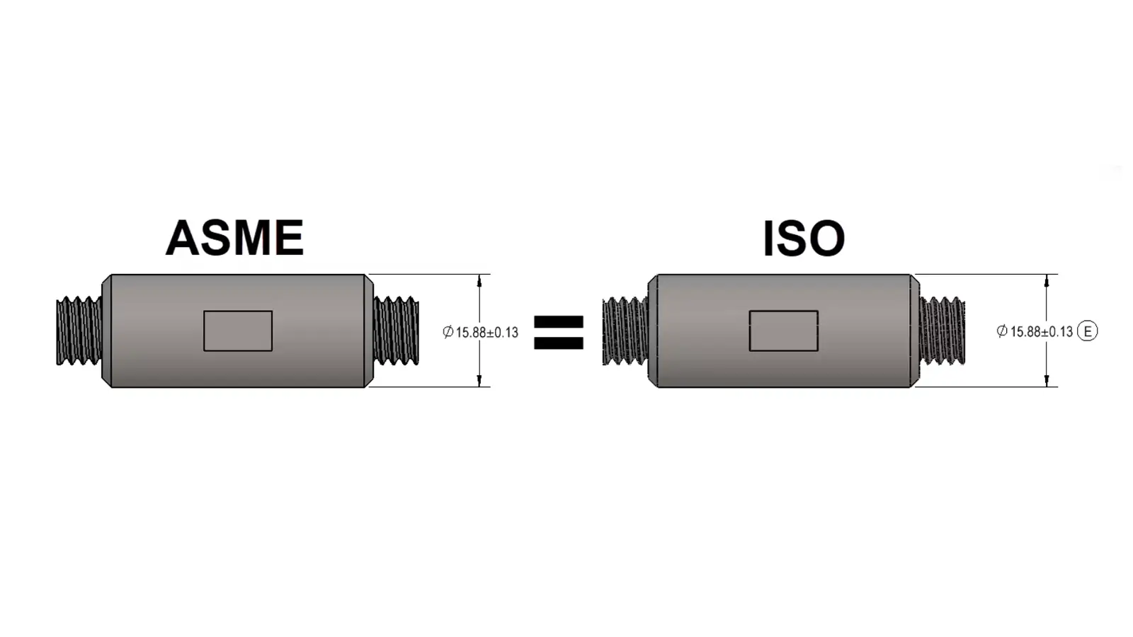
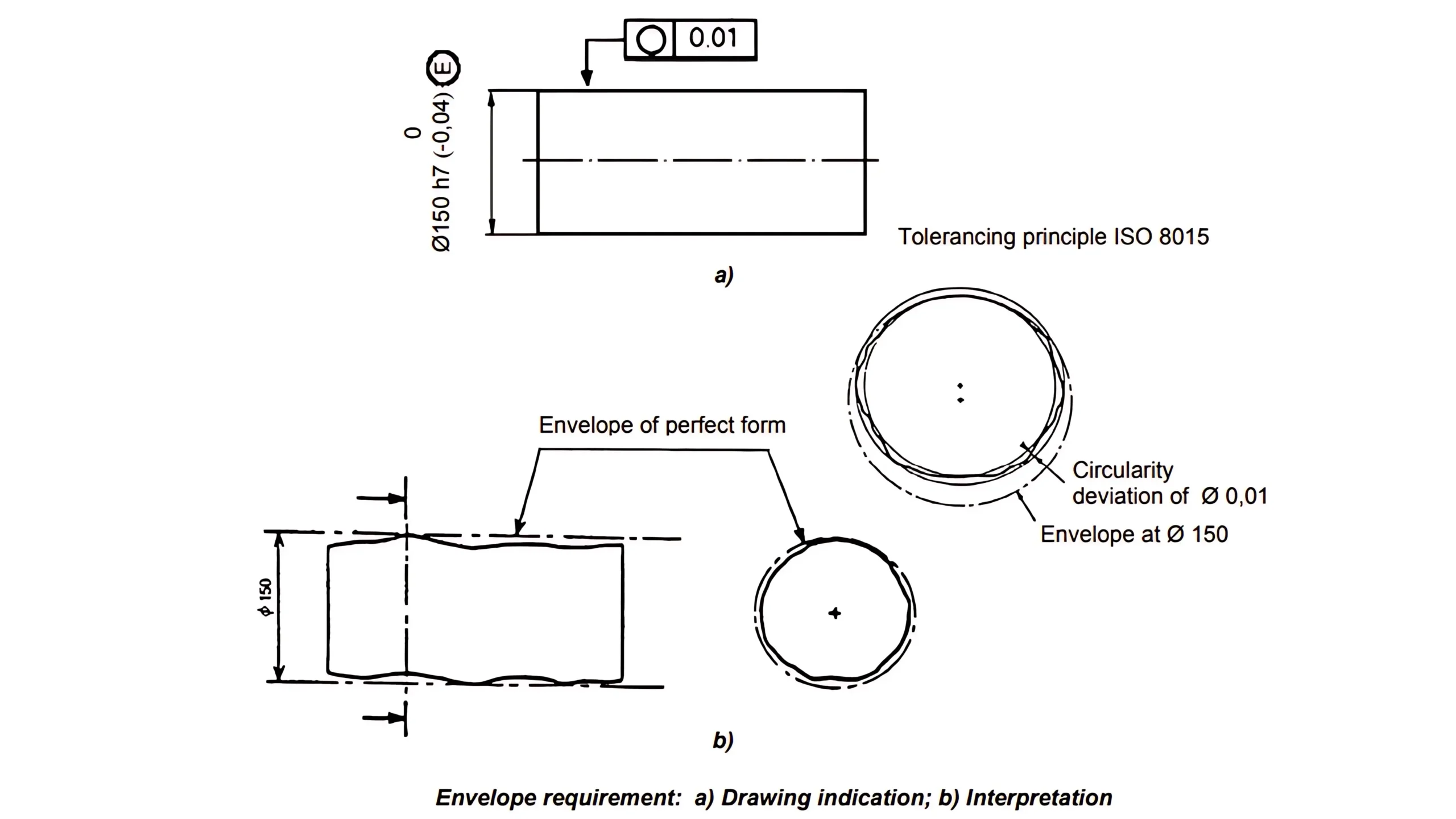
    Figure 1 shows a drawing example of a cylindrical feature controlled by the envelope requirement GD&T. The drawing conveys that the surface of the cylindrical feature must not extend beyond the envelope of perfect form at maximum material condition of Ø150, and each actual local size must be no less than Ø149,96.

    This means that when the true cylindrical feature deviates from its MMC to LMC, the actual form is allowed to deviate with the same deviation. And the surface of the cylindrical feature shall be exactly cylindrical when all actual local size are at the maximum size of Ø150.

    Envelope Requirement

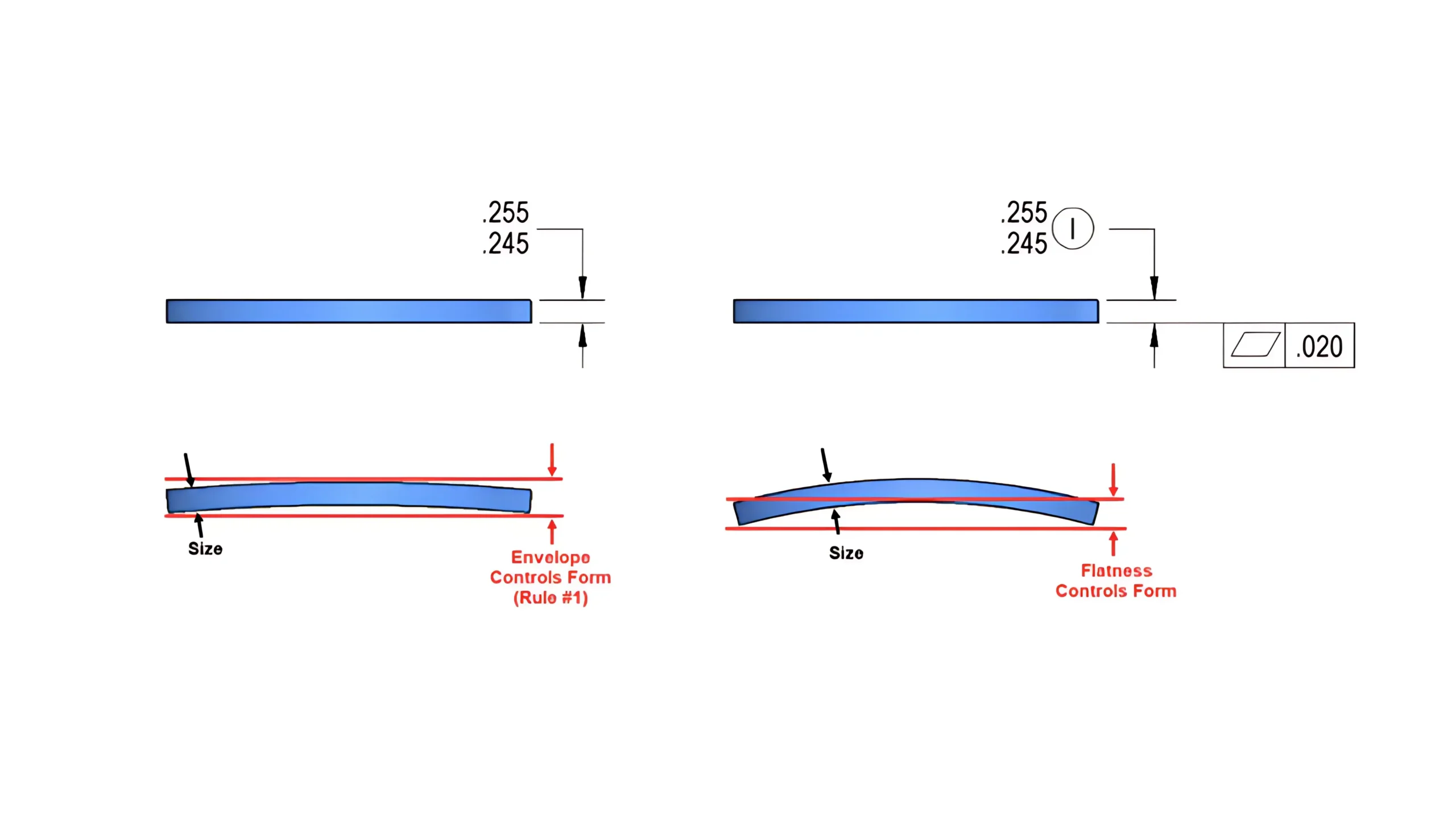
    In some specific cases the maximum form deviations permitted by the envelope requirement may be too large for satisfactory functioning of the mating parts, and thus additional form tolerances shall be used to further control the form of the features of size.

    Figure 2 is such a case where a circularity tolerance is indicated to provide a compulsory restriction on the cylindrical feature.

    Just as same as Figure 1, each actual local size of the cylindrical feature in Figure 2 must remain within the size tolerance of 0,04 and could vary between Ø150 and Ø149,96. But there is an additional circularity tolerance of Ø0,01 indicated on the drawing.

    This means that each true cross-section of the feature should lie within a cirque comprised with two perfect concentric circles whose diameters differ 0,01.

    In short, the circularity tolerance shrinks the allowable tolerance provided by the envelope requirement GD&T on the feature’s circularity. The envelope requirement GD&T can control the form of features of size as a whole by size tolerance control(including circularity and straightness in this case). But more detailed control should use concrete GD&T Form Symbols.

    4. Envelope Requirement GD&T VS Maximum Material Condition

    There are certain similarities between envelope requirement GD&T and Maximum Material Condition(MMC), and also some differences.

    4.1. On Features

    Envelope requirement GD&T can only control the form of a single feature of size by its size tolerance, while MMC can control certain complex geometric features.

    Envelope Requirement GD&T VS Maximum Material Condition

    4.2. On Indications

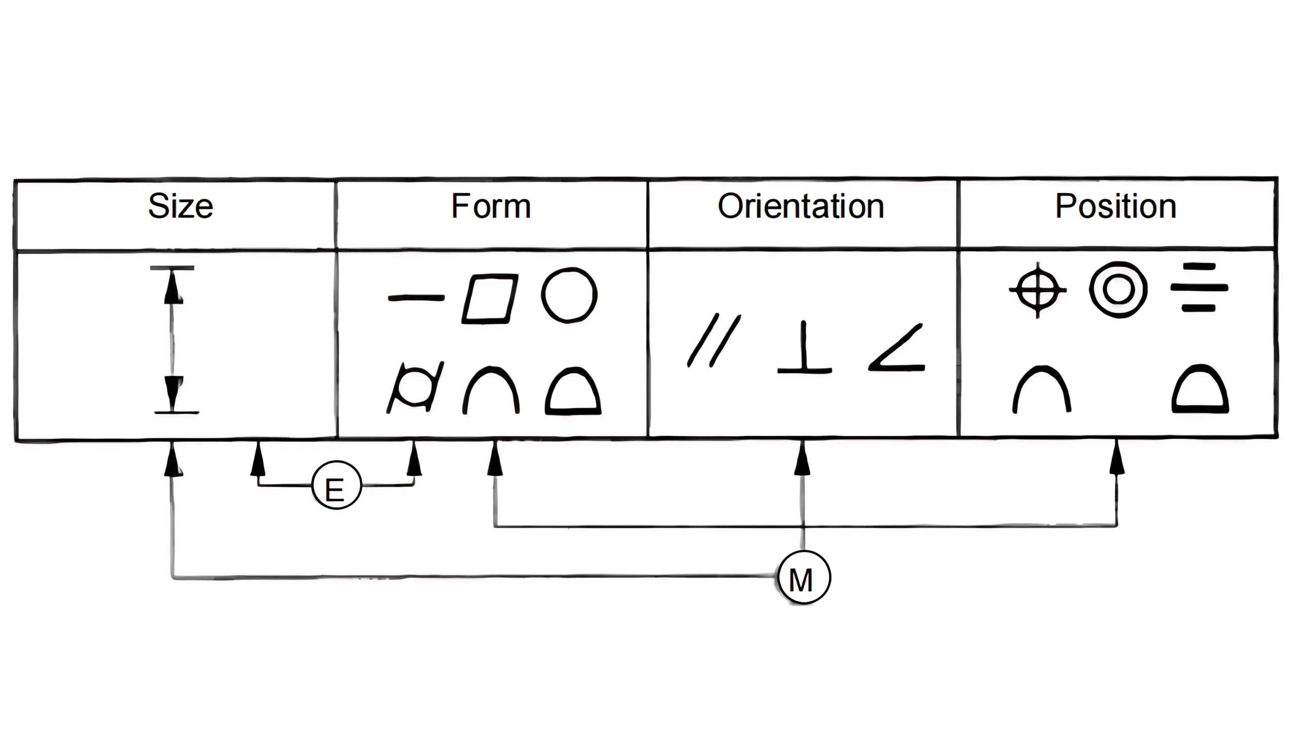
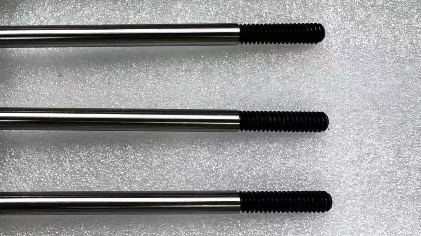
    As we have explained above, envelope requirement is the default rule in ASME Y14.5 Standards, also called Rule #1 or Envelope Principle. This means envelope requirement does not have specific symbol in ASME Y14.5 Standards. While in ISO Standards, the envelope requirement is indicated on engineering drawings by symbol E after the size tolerance.

    However, the Maximum Material Condition should always be indicated as symbol M after the geometric tolerance value within the feature control frame on engineering drawings.

    4.3. On Effects

    Envelope requirement can be seen as a simple version of Maximum Material Condition(MMC) since certain effects of envelope requirement are as same as that of the MMC.

    Maximum Material Condition refers to the situation where the contained material of a feature is at the maximum allowable side. Envelope requirement GD&T defines that the form of a feature of size is controlled by the size tolerance and would be exactly perfect when the size is at the maximum material condition. The entire feature must be controlled within the perfect maximum virtual envelope.

    Both envelope requirement and MMC allow the form of features of size to deviate as same as the deviation any actual local size away from the maximum size.

    However, the envelope requirement is a kind of overall control in which form is controlled by the size tolerance, meaning that the form would not be allowed to deviate from the perfect form when the size is at its maximum material condition.

    While the MMC is a kind of material modifier used with particular geometric tolerances, meaning that even when the feature is at its MMC, the geometric feature is still allowed to deviate to some extent.

    MMC provides bonus tolerance for the indicated geometric tolerance, while the form deviation under envelope requirement is default and is controlled by the size tolerance.

    5. Envelope Requirement GD&T VS Independency GD&T

    Envelope requirement GD&T and independency GD&T are contrast to each other.

    5.1. On Indications

    Envelope requirement is default in ASME Y14.5 Standards, but has specific symbol(E) in ISO Standards. Contrast to envelope requirement, independency GD&T is the default rule in ISO Standards, but has specific symbol(I) in ASME Y14.5 Standards.

    Both their symbols are indicated after the size tolerance.

    5.2. On Effects

    Envelope requirement GD&T defines that the form is controlled by the size tolerance while the two keep independent to each other according to independency GD&T.

    In short, independency GD&T cancels the effects of envelope requirement GD&T.

    Envelope requirement can control the form of features of size as a whole by the size tolerance. Therefore, it is usually used on features for mating functions. While independency GD&T allows much more deviation on the form of features, thus is usually used for features not to be assembled with mating parts.

    independency VS envelope

    6. Conclusion

    Envelope requirement GD&T shares important role in engineering and manufacturing. This article has explained the envelope requirement GD&T as much detailed as possible.

    Other Articles You Might Enjoy

    5 axis CNC machining equipment photo

    What is 5-axis Machining? A Complete Guide.

    5-Axis CNC machining is a manufacturing process that uses computer numerical control systems to operate 5-axis CNC machines capable of moving a cutting tool or a workpiece along five distinct axes simultaneously.

    simultaneous 5 axis machining aluminum

    Which Country is Best for CNC Machining?

    China is the best country for CNC machining service considering cost, precision, logistic and other factors. Statistical data suggests that China emerges as the premier destination for CNC machining.

    5 axis cnc milling machining services

    Top 5 Prototype Manufacturing China

    Selecting the right prototype manufacturing supplier in China is a critical decision that can significantly impact the success of your product development project.

    bladed disks (blisks) check by CMM

    CNC Machining Tolerances Guide

    Machining tolerances stand for the precision of manufacturing processes and products. The lower the values of machining tolerances are, the higher the accuracy level would be.

    Let's get your projects started, together!

    Get custom parts machined in high quality, delivery on time.