If specific features are designed to be controlled on orientation, location, or any geometric tolerances in restrained condition, a restrained condition note should be clearly indicated on the engineering drawing.
And the note should point out which features are to be restrained, how they are to be restrained, and to what extent they are to be restrained.
Figure 1 below shows an example of a part under restraint specified on the runout control. The restrained condition mimics the state where the part will reside in at final assembly.
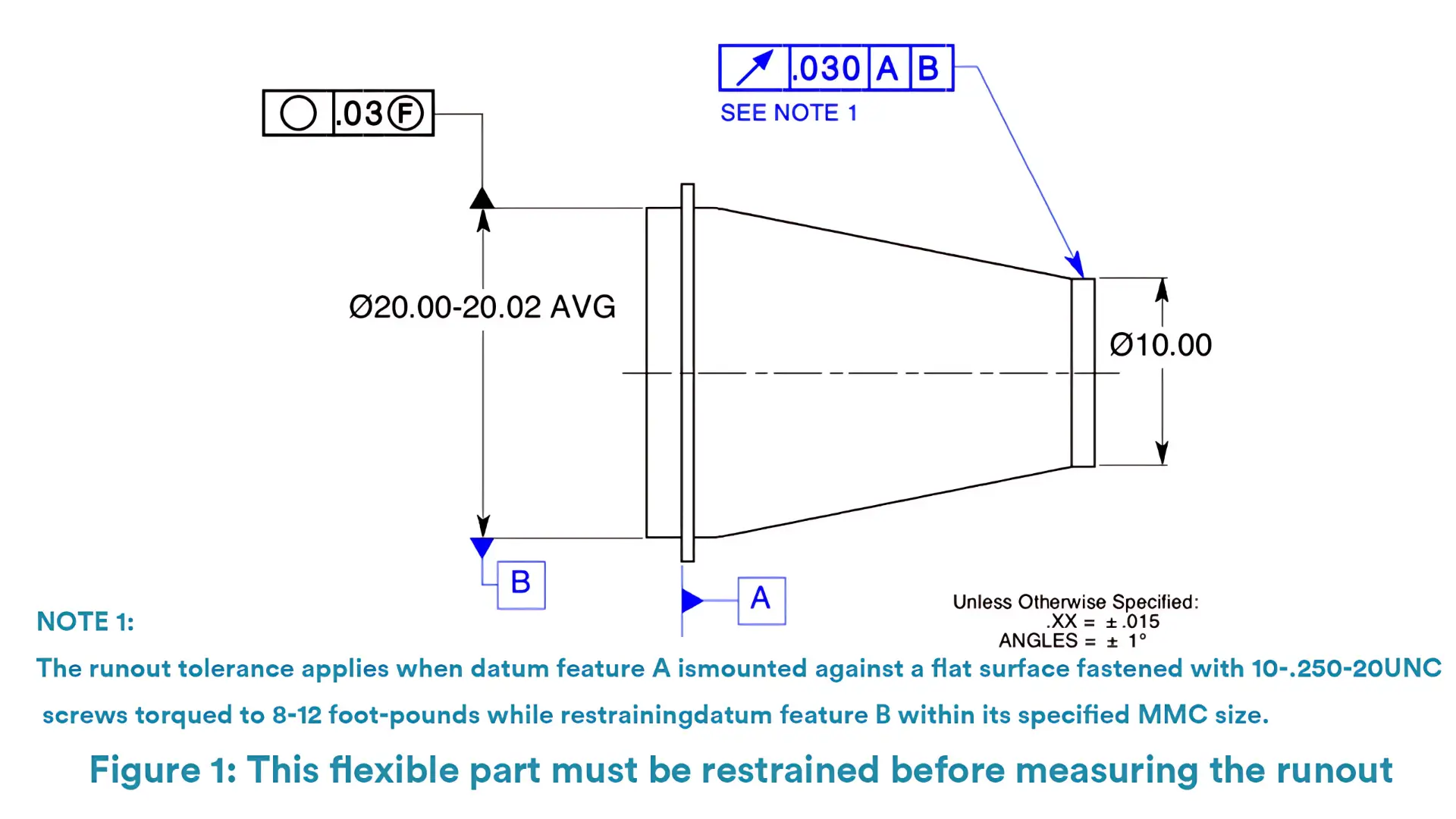
In this example, the Note 1 clearly states the restrained condition of the specific feature on its runout tolerance.
The note confines that during inspection the datum feature A should be mounted against a flat surface fastened with 10-.250-20 UNC screws torqued to 8-12 foot-pounds and the datum B should be restrained within its specified MMC size.
Only under such a restraint can the runout tolerance be measured. And the restrained condition simulate the final state of the part in the assembly. Therefore, if the runout passes measurement, the part can be assembled well with its mating part finally.
If specific features are designed to be controlled on dimension or geometric tolerances in the free state, the free state symbol should be placed within the feature control frame after the tolerance value and any modifiers.
One of the most typical situations where the free state symbol will be applied on a specific feature is when checking the circularity of average diameter. Average diameter tolerance is usually applied on the diameters of non-rigid cylindrical parts.
Figure 2 below is an example of a part with free state symbol for circularity of average diameter.
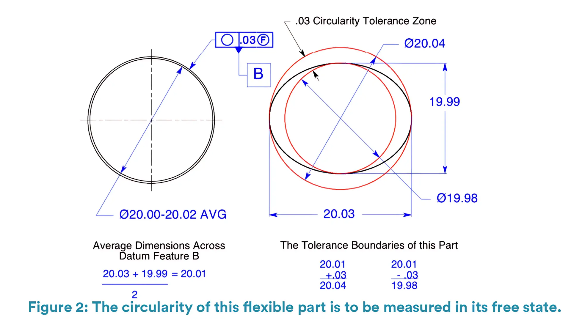 In this example, the dimension tolerance is followed by AVG, the abbreviation of “average”, indicating that the measurements are to be averaged as shown in the Figure 2 above.
The upper boundary of the maximum average dimension is the maximum average 20.02 plus the circularity tolerance .03. And the lower boundary of the maximum average dimension is 20.02 minus .03.
In addition, the upper boundary of the minimum average dimension is the minimum average 20.00 plus the circularity tolerance .03. While the lower boundary of the minimum average dimension is 20.00 minus .03.
These extreme dimensions are not allowed to be occur in the same cross section at the same time.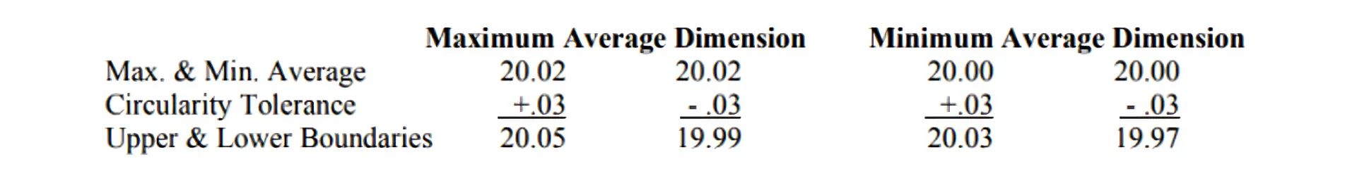
If the average of measurements of this feature lies within the average size tolerance zone, the feature would pass on circularity.
For instant, if the 20.00 diameter in Figure 2 is measured 20.03 in one direction and 19.99 in the other direction finally, then the average diameter is 20.01, which lies within the average size tolerance zone. Therefore, the average diameter is in tolerance and up to the standard.
And pay attention to that at least four measurements should be taken on the specific feature for accuracy.

5-Axis CNC machining is a manufacturing process that uses computer numerical control systems to operate 5-axis CNC machines capable of moving a cutting tool or a workpiece along five distinct axes simultaneously.

China is the best country for CNC machining service considering cost, precision, logistic and other factors. Statistical data suggests that China emerges as the premier destination for CNC machining.

Selecting the right prototype manufacturing supplier in China is a critical decision that can significantly impact the success of your product development project.

Machining tolerances stand for the precision of manufacturing processes and products. The lower the values of machining tolerances are, the higher the accuracy level would be.