Home » Blog » How to install and remove dowel pins for CNC parts?

How to Install and Remove Dowel Pins for CNC Parts?

By Lucas Lo

Published: Apr. 24, 2025

Updated: Oct. 04, 2025

Table of Contents

    As a CNC processing service provider, customers often ask us to install pins on CNC machined parts so that they can use them directly after receiving the parts.

    When it comes to dealing with dowel pins, whether for removal or installation, mastering proper techniques is key to ensuring component integrity and project success.

    In this blog, we’ll provide a comprehensive guide covering both removal and installation processes, along with step-by-step instructions, tool recommendations, and practical tips to help you handle dowel pins with precision.

    Key Takeaways:

    1. Dowel pins are precision cylindrical connectors for alignment and positioning, available in straight, tapered, spiral, and threaded variants for different applications.
    2. Production depends on size and quantity – automatic lathes for small diameters (≤2mm) in bulk, CNC lathes for larger diameters and flexible batch sizes.
    3.  Three fit types used: interference fit for permanent mounting, transition fit for precision removable assemblies, and adhesive fixing for light loads.
    4. Proper removal requires specific tools and methods including thermal shock, controlled drilling, and pullers, with emphasis on safety protocols and damage prevention.

    1. What is a Dowel Pin?

    A dowel pin is a common connecting element used to align or hold parts together. Locating pins are critical to ensure consistent workpiece alignment, minimize tolerance accumulation, and maintain assembly accuracy.

    2. What are The Main Features of Dowel Pins?

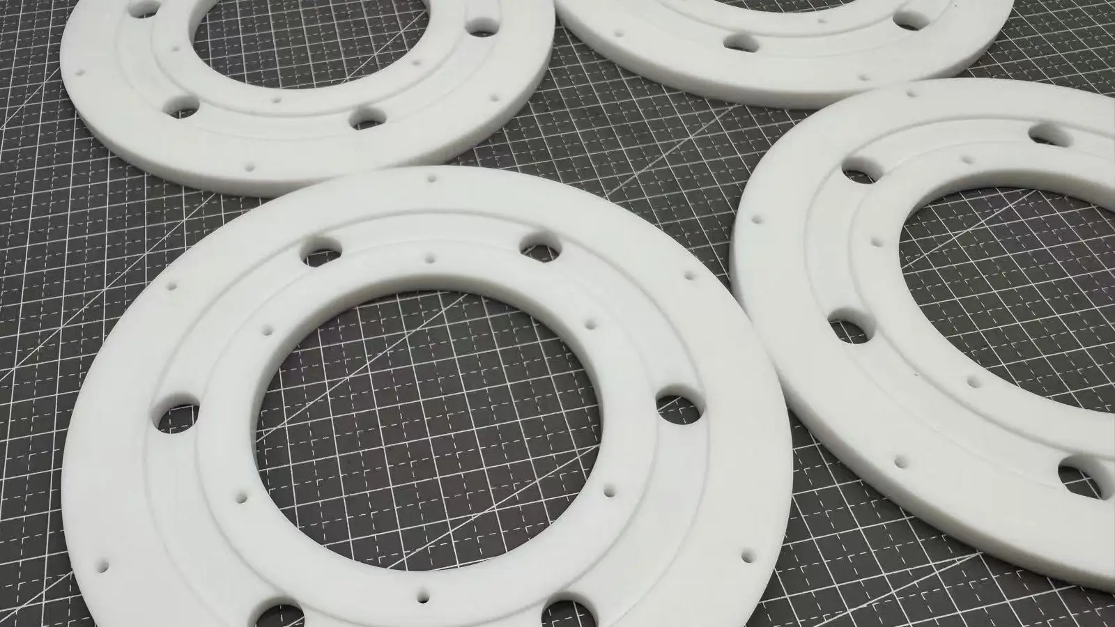
    The appearance design of dowel pins is usually high-precision cylinders with small diameter tolerance and smooth surface.

    Materials used to make dowel pins are classified into metallic and non-metallic.

    Metal: Stainless steel and alloy steel are often used due to their strength, hardness, and abrasion resistance, making them suitable for heavy loads and shocks.

    Non-metal: Nonmetal materials like plastic and ceramic are used. Plastic dowels (such as nylon, paraformaldehyde) are insulating, corrosion-resistant and lightweight.

    There are several types of dowel pins: straight type, tapered type, spiral type, and threaded type.

    Straight dowel pins: standard cylindrical shape, headless.Straight Dowel Pins

    Tapered dowel pins: Slightly thinner at one end for ease of installation and adjustment.Tapered Dowel Pins

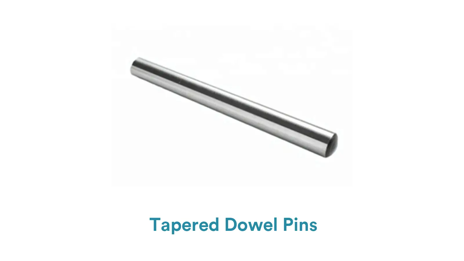
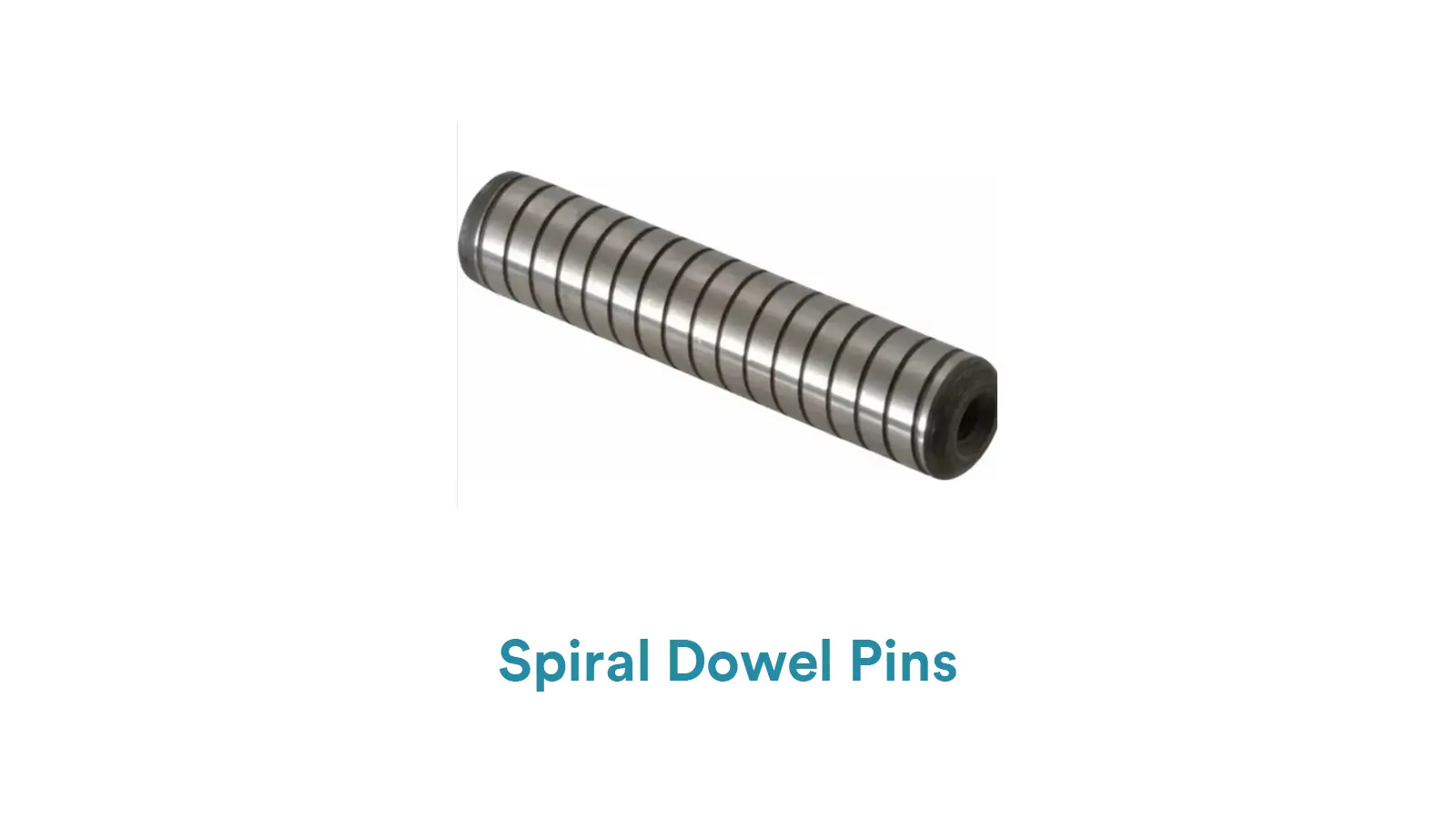
    Spiral Dowel Pins: Spiral grooves on the surface produce a slight elastic deformation to enhance the fixing effect.

    Spiral Dowel Pins

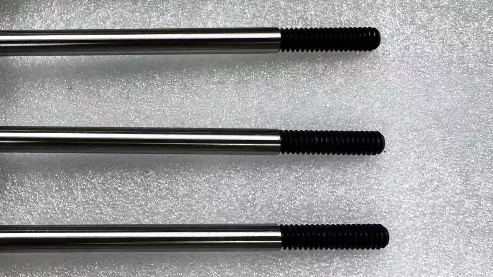
    Threaded dowel pins: threaded at one or both ends for easy removal.Threaded Dowel Pins

    3. Commonly Used Specifications of Dowel Pins

    There are usually two more commonly used specifications, metric size (DIN/ISO standard) and inch size (inch series), where the metric size ranges from Ø1mm ~ Ø20mm in diameter, and the length is usually 3mm ~ 120mm, while the inch size ranges from 1/16 inch ~ 1 inch in diameter, and the length is from 1/4 inch ~ 4 inch.

    4. What Are The Differences Between A Dowel Pin And A Screw?

    ItemDowel PinsScrews/Bolts
    Main FunctionPrecise alignment and positioningClamping and fastening
    StructureSmooth,nothreads(maybe chamfered)Threaded with drive head
    Installation MethodPress-fit into mating holesScrewed using tools
    ReusabilityNot designed for frequent removalDesigned for repeated assembly/disassembly

    5. What Are Dowel Pins Used For?

    Positioning pins have a wide range of uses in machinery manufacturing, assembly and various industrial fields, mainly including the following aspects:

    – Positioning and precise assembly:

    In mechanical assembly, it is used to determine the exact relative position between parts to ensure mounting accuracy.

    – Restriction of parts movement:

    In mechanical structures, locating pins are used to restrict the movement or rotation of parts in a particular direction, playing a fixed and restraining role.

    – Facilitate disassembly and maintenance:

    In equipment maintenance or parts replacement, positioning pins can help maintenance personnel to quickly and accurately find the location of the need to disassemble and install to improve maintenance efficiency.

    6. What Are The Main Industries Where Dowel Pins Are Used?

    The main areas of application for locating pins are as follows:

    – Automotive manufacturing, including part positioning for body welding and chassis assembly.

    – Tooling manufacturing for the positioning of parts in injection molds and stamping dies.

    – Electronic equipment manufacturing, such as printed circuit board assembly and electronic equipment housing assembly.

    – Aerospace, used to assemble structural and engine components.

    7. How to Make a Dowel Pin?

    According to the quantity and precision of dowel pins, you can choose to produce them with CNC lathe and automatic lathe.

    For dowel pins with diameters below 2mm, they are usually produced with automatic lathes, especially for large quantities, using centerless grinders and automatic lathes with automatic feeding system for high efficiency production, which can realize turning, breaking and chamfering at one time.

    For small quantity and high precision pins with diameter above 2mm, CNC lathe and cylindrical grinder are used for production with more flexibility. Details can be found in the following table:

    Diameter/Batch SizePreferred EquipmentAlternative SolutionsFollow-up Processes
    ≤2mm,Large BatchAutomatic Lathe

    CNC Lathe

    (low efficiency)

    Optional precision grinding (depending on tolerance requirements)
    >2mm,Large BatchCNC Lathe + Centerless GrinderAutomatic Lathe (limited to short parts)Mandatory precision grinding
    Small to Medium Batch (any size)CNC LatheCommon Lathe (low efficiency)Cylindrical Grinder(for high-precision requirements)

    8. How to Install Dowel Pins?

    Installation Fit of the Pins

    According to the functional requirements (positioning, force transmission, fixation, etc.) and precision requirements of the pins, the installation fit of the pins is mainly divided into three categories: interference, transition, and clearance.

    -Interference Fit:

    The pin hole diameter is slightly smaller than the pin diameter and needs to be pressed in (Press Fit) to provide high rigidity.

    Features: Pin diameter slightly larger than hole diameter, press or heated hole/cooled pin installation required.

    ISO standard:

    H7/p6 (pin: p6, hole: H7) → medium interference, press fitting required.

    H7/s6 (pin: s6, hole: H7) → high interference, hot or cold installation required.

    Application Scenario:

    High load transfer (e.g. engine crankshaft locating pins).

    Permanent fixing (disassembly can damage the hole or pin).

    Transition fit:

    The clearance between the pin and the hole is extremely small. It allows for manual installation(Slip Fit) and is easy to disassemble.

    ISO standard:

    H7/m6 (pin: m6, hole: H7) → Medium positioning accuracy, requires mallet tap installation.

    H7/n6 (pin: n6, hole: H7) → higher positioning requirements, may require press-in.

    Application Scenario:

    Precision machinery assembly (e.g. mold guide pins, gearbox positioning).

    Connections that require removable but no relative motion.

    Glued Fixing:

    With anaerobic adhesive (e.g. Loctite) to enhance retention.

    Features: Can compensate for tolerances, easy installation, even stress distribution.

    ISO Standards:

    ISO 10964 (Thread locking) for anaerobic adhesives.

    ISO 9664 (General requirements for structural adhesives) for epoxy resins.

    ISO 14569 (Specifications for instant-drying adhesives) for instant-drying adhesives.

    Application Scenarios:

    Light-load environments, non-ferrous metals or thin-walled parts, areas requiring sealing.

    The Required Tools and Steps to Install Dowel Pins

    When installing the pin, we first need to consider the type of fit of the pin, whether it is an interference fit, or a transition fit.

    If it is an interference fit, using a hydraulic press, align the pin with the hole and press it in slowly with the press (avoid tilting). Another method is to heat the hole to expand it, insert the pin, and shrink it to lock it when it cools.

    If it is a transition fit, utilize a rubber or brass hammer and tap the pin into place by aligning the hole.

    Tips for Accurate Installation

    -Pre-alignment: Use pilot holes or bushing guides for multi-pin setups.

    -Lubrication: Apply molybdenum disulfide grease for high-friction materials (e.g., cast iron).

    -Post-installation Check: Measure protrusion with a depth micrometer (tolerance: ±0.1mm).

    9. How to Remove Dowel Pins?

    Different installation methods correspond to different disassembly methods. The details are as follows:

    -Interference Fit

    Use tools such as slide hammers and pullers; or disassemble after heating the parts being fitted or cooling the fitting parts.

    -Transition Fit

    Disassemble by gently tapping with hand tools or a wooden hammer; when it’s relatively tight, use a copper hammer, etc. If there are auxiliary fasteners, remove them first.

    -Adhesive Fixing

    Pry off after softening by heating; scrape off after dissolving with chemical solvents; scrape off small – area stubborn adhesives with tools.

    Dealing with Stubborn or Seized Dowel Pins

    Heat Expansion: Apply a heat gun (max 150°C) to the housing, then quench the pin with dry ice to create thermal shock.

    Drilling: Use a center drill (0.5mm smaller than pin diameter) to create a pilot hole, then expand with a step drill for controlled removal.

    Avoid Damage: Use a backup plate behind the part to prevent exit-side burring.

    Safety Protocols

    PPE: Wear anti-fog goggles and cut-resistant gloves.

    Lockout/Tagout (LOTO): Disconnect power sources for machinery-mounted pins.

    Tool Maintenance: Ensure punches are free of burrs to prevent marring pin surfaces.

    Common Issues and Troubleshooting

    IssueRoot CauseRemedy
    MisalignmentMachining tolerance stack-upUse GD&T datums for hole positioning; inspect with CMM.
    Loose FitWear from cyclic loadingReplace with oversize pins (e.g., +0.01mm) or sleeve.
    Seized PinsCorrosion or adhesivePre-apply anti-seize compound; use ultrasonic cleaning.
    Installation DamageExcessive hammer forceSwitch to press-fit tools; use alignment jigs.

    10. Preventing Damage to CNC Parts During Installation and Removal

    -Precise preparation before installation:

    use calipers and other precision tools to measure the pin hole and pin size, select the appropriate type of fit according to the needs, like easy disassembly and assembly selection of clearance fit.

    -Standardized operation during installation:

    align the locating pins and holes with the help of jigs and fixtures, give priority to the use of press-fit tools or hydraulic presses, avoid violent hammering, and use soft-faced hammers to tap manually.

    -Comprehensive inspection before disassembly:

    check the positioning pin and hole for corrosion, wear, corrosion first coated with corrosion-resistant lubricant to moisten.

    -When disassembling, operate with caution:

    use appropriate tools such as positioning pin puller, and gradually apply force to disassemble from a low force.

    11. How to Choose the Right Dowel Pin Size?

    Selection of suitable positioning pins should be considered from the following three aspects:

    -Material: according to the scene selection of strength, hardness, wear resistance,

    corrosion resistance of the appropriate material. Such as CNC machining equipment selection of high-quality alloy steel; automotive assembly line with hardened; chemical equipment with stainless steel positioning pins.

    -Tolerance: Size tolerance and matching hole matching, high precision positioning needs small tolerance. Shape tolerance (cylindricity, straightness, etc.) should be ensured, such as machine tool table positioning, strict control of straightness error.

    -Length and diameter: length according to the thickness of the installation part, can pass through the parts and easy to operate, but not too long.

    Diameter according to the positioning accuracy, load-bearing capacity and space selection, small equipment with limited space can choose a small diameter and optimize the structure.

    12. Conclusion

    In the field of machinery, positioning pins, though small, are the key to accurate positioning and structural stability. From installation to dismantling, every step of the process is related to the smooth operation of the mechanical system.

    Other Articles You Might Enjoy

    5 axis CNC machining equipment photo

    What is 5-axis Machining? A Complete Guide.

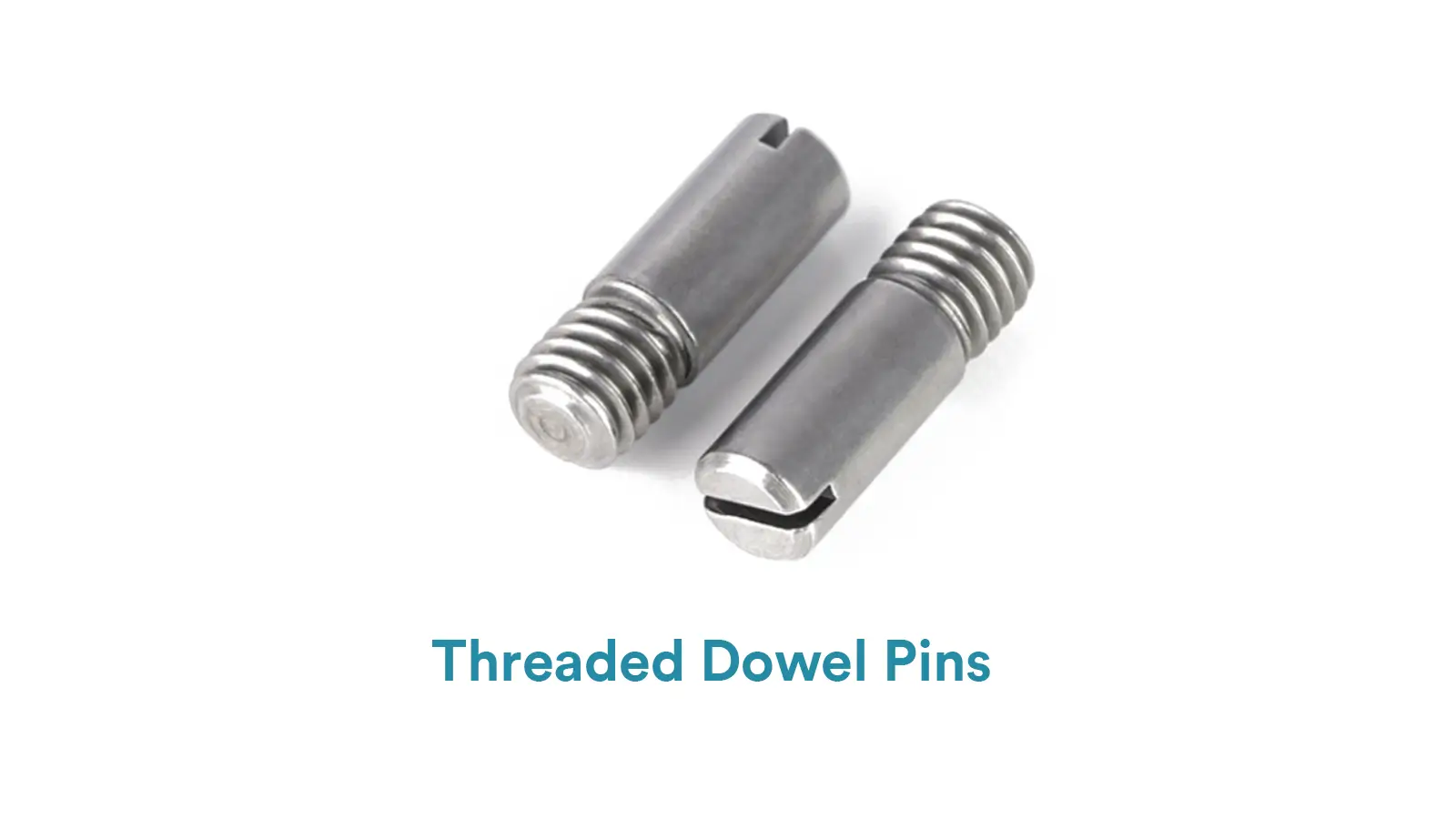
    5-Axis CNC machining is a manufacturing process that uses computer numerical control systems to operate 5-axis CNC machines capable of moving a cutting tool or a workpiece along five distinct axes simultaneously.

    simultaneous 5 axis machining aluminum

    Which Country is Best for CNC Machining?

    China is the best country for CNC machining service considering cost, precision, logistic and other factors. Statistical data suggests that China emerges as the premier destination for CNC machining.

    5 axis cnc milling machining services

    Top 5 Prototype Manufacturing China

    Selecting the right prototype manufacturing supplier in China is a critical decision that can significantly impact the success of your product development project.

    bladed disks (blisks) check by CMM

    CNC Machining Tolerances Guide

    Machining tolerances stand for the precision of manufacturing processes and products. The lower the values of machining tolerances are, the higher the accuracy level would be.

    Let's get your projects started, together!

    Get custom parts machined in high quality, delivery on time.