Home » Blog » Large Part 5-Axis Machining vs Small Part 5-Axis Machining

Large Part 5-Axis Machining vs Small Part 5-Axis Machining | The ECOREPRAP Expert Guide

By Lucas Lo | Published: Sep. 21, 2025

Table of Contents

    In our previous blog, we explored different types of 5-axis CNC machines and highlighted some of China’s top 5-axis machining service providers. The truth is, every factory has its own strengths—some specialize in large-scale 5-axis components, while others focus on small precision parts.

    Although the core principles of 5-axis machining remain the same, the differences between large and small part machining are significant. From the equipment used to the processes involved, the challenges couldn’t be more different. Mixing up these requirements can easily lead to costly overruns, missed deadlines, or even scrapped parts.

    Key Takeaways

    • Large part 5-axis machining handles components over 500mm. The main challenge is controlling deformation from gravity and stress as large amounts of material are removed. Large 5-axis machined part, including Impellers, wheel hubs, tire mold, lamp mold and medical parts are explained.
    • Small part 5-axis machining is for hand-sized or smaller parts. The focus is on ultra-high precision and a flawless surface finish. Examples: Bionic hand parts, and UAV components.
    • Why ECOREPRAP stands out as a top 5-axis machining partner because it has the specialized equipment and expertise for both large and small parts.

    1. Large Part 5-Axis Machining

    1.1. What Is Large Part 5-Axis Machining?

    Large-part 5-axis machining refers to machining operations performed using 5-axis CNC machines, specifically designed to handle large and geometrically complex components. While there is no universally defined size standard, at ECOREPRAP, we classify any part with finished dimensions exceeding 500mm as large-part 5-axis machining.5-Axis Machining of Aluminum Motor Cases

    Key features include:

    • High Complexity: These parts often have intricate features like deep pockets, sloped surfaces, and complex curves that would be impossible to create in a single run with a traditional 3-axis machine.1
    • Technically Advanced: It’s not just about running a machine; it’s a sophisticated process that requires expertise in multiple high-tech fields. This includes everything from CAM programming and fixture design to stress control and on-machine inspection.
    • Complex Process & Long Lead Times: The machining process for a single part can take days or even weeks, involving multiple stages like roughing, semi-finishing, and final finishing. Strict quality checks are essential throughout the entire process.
    • The Power of “One-and-Done” Clamping: For very large parts, having to reposition or re-clamp them can completely ruin precision and cause major delays. 5-axis technology’s ability to machine the entire part in a single setup offers unmatched value. It ensures consistent alignment from start to finish, guaranteeing superior accuracy and tight geometric tolerances.2

    1.2. Equipment Requirements for Large Part 5-Axis Machining

    As we know, compared to 3-axis machines, 5-axis equipment comes with higher costs. Large 5-axis parts are not only bigger in size but also typically heavier.

    Machining large parts with 5-axis technology generally requires heavy-duty gantry-type 5-axis machines or large rotary table (cradle-type) machines. The machine bed, guideways, and spindle must all be designed for heavy cutting operations.5 axis CNC machining equipment photo

    These machines need to meet the following requirements:

    • Extreme machine rigidity & excellent stability: The machine bed is usually made of high-grade cast iron or polymer concrete to absorb vibrations and resist massive cutting forces. The entire machine structure must be as solid as a rock to ensure no deformation occurs during heavy cutting.
    • High spindle torque: Rough machining requires removing large amounts of metal material.3 The spindle must provide substantial and consistent low-speed torque to drive large-diameter face mills and corn cob cutters for highly efficient cutting.
    • High-load capacity CNC rotary table: The machine’s A/C-axis or B/C-axis rotary table must be able to steadily carry workpieces weighing several tons to tens of tons while maintaining extremely high rotational positioning accuracy under heavy load—without any shaking or sinking.
    • Long travel ranges (X, Y, Z axes): This is a basic requirement. The machine’s travel distance must fully cover all machining areas of the workpiece.
    • Advanced thermal management & accuracy compensation: Due to long machining cycles, ambient temperature and internal machine heat can cause thermal deformation.4 Top-tier equipment is equipped with thermal compensation systems that correct precision errors caused by thermal expansion and contraction of each axis in real time.
    • In-machine measurement system: Integrating high-precision machine probes and laser tool setters is essential. They are used to automatically calibrate workpiece coordinate systems during machining, measure critical dimensions, and automatically compensate for tool wear. This is key to achieving “right-first-time” machining.

    1.3. Three Major Challenges in Large-Part 5-Axis Machining

    Large-part 5-axis machining is no easy task. Below are its three main challenges:

    • Challenge 1: Gravity & Stress Deformation

      This is the primary and most critical challenge. The sheer weight of the workpiece can cause sagging and deformation in its structure. Additionally, large forgings or castings often contain significant internal residual stresses from their manufacturing processes. As material is removed during machining, these stresses redistribute and release, leading to unpredictable warping or twisting of the part.5

      • Solution: This relies on specialized fixture design (to provide uniform support), the use of symmetric layer-by-layer machining strategies to progressively relieve stress, and cutting simulation analysis before programming.
    • Challenge 2: Fixture Design and Workholding Difficulties

      Large parts require custom fixtures to ensure they remain secure and undeformed during machining.6 This not only increases the complexity of fixture design but also demands higher technical skill from machine operators to install fixtures accurately and avoid machining errors.

    • Challenge 3: Tooling Management and Long-Reach Machining

      When machining deep cavities or high walls, long or extended-reach tools are typically required. Their low rigidity makes them susceptible to vibration (chatter) during cutting, which can damage the tool, worsen surface quality, and deepen tool marks. Effectively controlling vibration and managing tool deflection is essential for achieving high precision.

      • Solution: Utilize the tool axis tilting capability of 5-axis machines and adopt processes like plunge milling for roughing, which directs cutting forces axially and maximizes tool rigidity. Additionally, the use of dynamically balanced anti-vibration tool holders is critical.high-precision 5-axis CNC machining

    Here are some examples of the large 5-axis parts that we at ECOREPRAP have successfully machined.

    1.4. Aluminum Impeller 5-Axis Machining

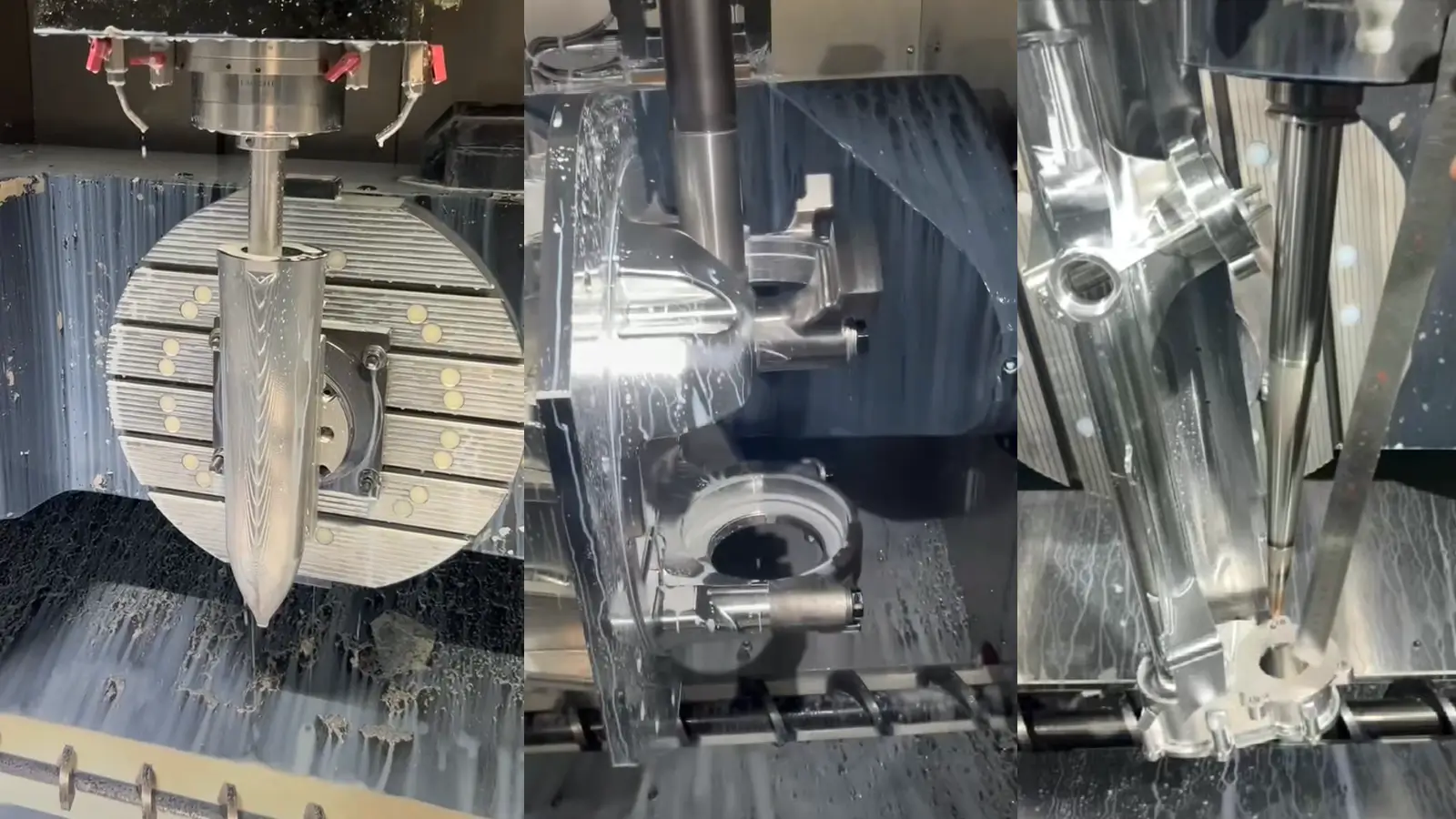
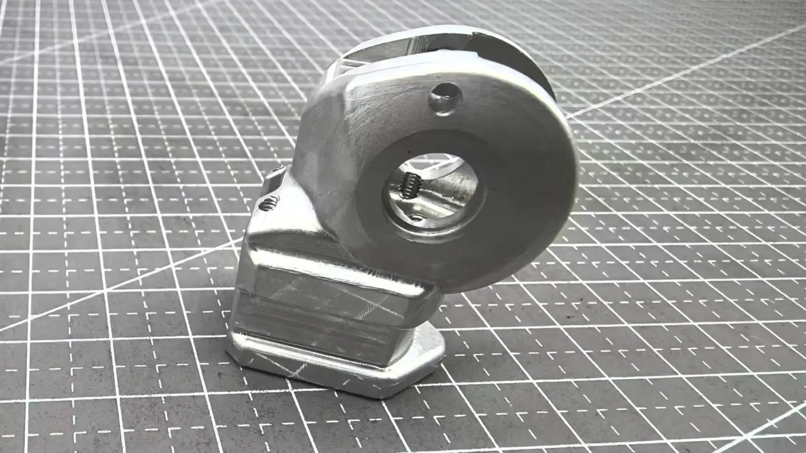
    The aluminum impeller is a classic yet challenging example of 5-axis machined components. For machining aluminum impellers, 5-axis technology is the only economically viable and practical solution.5 axis machining blisk

    The core difficulty lies in avoiding interference issues caused by their complex geometry—a challenge overcome through 5-axis simultaneous motion and intelligent programming.2

    Key Features:

    • Geometric Complexity: Composed of multiple highly twisted, spatially distributed blades, forming narrow and deep flow channels between them.3 This is a typical closed impeller structure.
    • Material: Aluminum alloy (e.g., 6061, 7075).4 The advantage is good machinability, but the soft nature of the material demands higher rigidity for thin-walled structures.
    • Critical Requirements: Blade profile accuracy, surface finish (directly affecting aerodynamic/hydrodynamic efficiency), dynamic balance performance, and consistency between blades.

    Challenges and Solutions in 5-Axis Impeller Machining

    Tool Interference & Accessibility

    This is the foremost challenge. The highly twisted blades and complex three-dimensional envelope make it impossible for 3-axis machines or standard end mills to fully access the pressure side and suction side of the blades.

    5-Axis Solution: Continuous adjustment of the tool axis vector via 5-axis programming allows the tool to tilt to an optimal angle within narrow flow channels. This ensures full access to target areas while avoiding collisions with adjacent blades. Full-range collision detection in CAM software is essential.

    Thin-Wall Deformation & Chatter

    To maximize efficiency, impeller blades are often designed with extremely thin walls (especially at the tips). Softer materials like aluminum are particularly prone to deformation and vibration.

    Challenges:

    Cutting forces can deflect thin blades, leading to springback and deviations in dimensional accuracy and surface profile.6

    Chatter vibrations leave visible marks on the blade surface, degrade finish quality, and may cause tool breakage or part rejection.

    5-Axis Solution:

    • Point Milling: Using the tool’s side edge instead of its tip reduces radial cutting forces and minimizes deformation.
    • Short & Rigid Tools: By adjusting the tool angle, shorter and sturdier tools can access deep channels, enhancing rigidity and suppressing vibration.
    • Optimized Cutting Parameters: High spindle speed, low depth of cut, and high feed rates minimize cutting forces.

    Complex Toolpath Programming

    Challenges:

    • Roughing: Efficiently and safely removing large amounts of material between blades while leaving uniform stock for finishing.
    • Finishing: Generating smooth, continuous toolpaths that fully cover complex surfaces while meeting tight tolerances and surface requirements.

    Tool Axis Control: Ensuring smooth and continuous changes in tool orientation to avoid sudden movements, machine jerks, or singularities.10

    5-Axis Solution:

    • Dedicated Impeller Modules: Advanced CAM software (e.g., HyperMILL, UG NX, PowerMILL) automates roughing strategies like plunge milling or spiral layer machining.
    • Drive Surface Programming: High-quality drive surfaces guide the tool for smooth and precise finishing operations.
    • Expert Post-Processing: A validated post-processor, perfectly matched to the machine tool, ensures collision-free and accurate G-code execution.

    Ensuring Blade-to-Blade Consistency

    All blades must have nearly identical geometry and weight to ensure optimal dynamic balance at high rotational speeds.

    • Challenges: Tool wear, minor fixture shifts, and cutting heat can introduce slight variations between blades.
    • 5-Axis Solution:
      • In-Process Measurement: Using machine probes to inspect key dimensions after or during machining of the first blade. Automatic compensation for tool wear is applied to subsequent blades.
      • Process Stability: Establishing and strictly following a proven machining process ensures identical conditions for every blade.

    1.5. 5-Axis Machining of Wheel Hubs

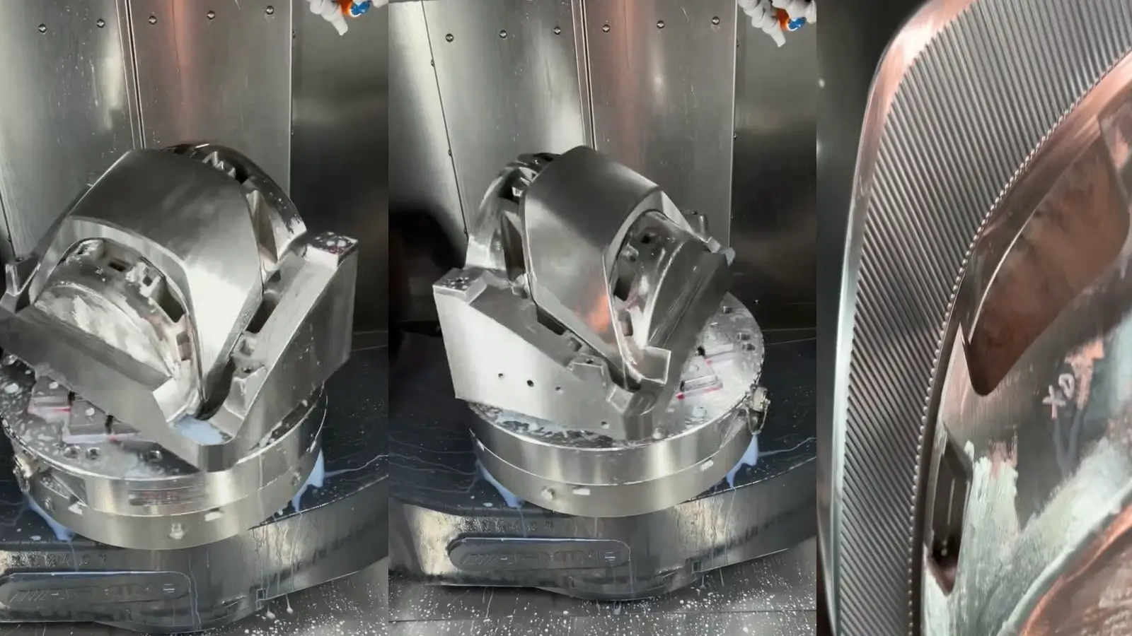
    As a critical rotating component in vehicles, wheel hubs present significant complexity in 5-axis machining due to stringent requirements for material properties, structural integrity, and key functional features.5 axis machining wheel hubs

    1.5.1. Wheel Hubs Geometric Structure

    • Spoke: Complex aesthetic surface requiring both visual appeal and heat dissipation; a key focus for 5-axis machining.
    • Rim: Tire mounting area, typically turned on a lathe (not primary for 5-axis milling).
    • Mounting Disc: Core interface with the vehicle axle, featuring high-precision elements:
    • Center bore: Locates and aligns with the axle.
    • Bolt holes (PCD): Tight positional tolerance () and perpendicularity.
    • Bearing seat: High dimensional accuracy (IT6 grade) and surface finish ().
    • Ventilation slots/cooling holes: Between spokes for brake cooling.

    1.5.2. Material and Processing Overview

    • Typical Materials: A356 cast aluminum alloy or 6061 forged aluminum alloy.
    • Machining Characteristics: Aluminum is soft and easy to cut but prone to built-up edge, tool deflection, and deformation in thin-walled areas. Sharp tools and optimized cutting parameters are essential.
    • Key Quality Requirements:
      • High dynamic balance: Uniform mass distribution to prevent vibration during high-speed rotation.
      • Superior mechanical and fatigue strength: Must withstand complex alternating impact loads as a safety-critical part.
      • Excellent surface quality: Appearance surfaces (spokes) require high finish () or even mirror effects, free of tool marks or chatter.
      • Tight dimensional and geometric tolerances: Especially for mating features on the mounting disc, critical to driving safety.

    1.5.3. Challenges & Solutions in 5-Axis Machining

    • Material Properties & Residual Stress

    High-performance hubs often use high-strength aluminum alloys like 6061-T651 or 7075-T6. However, these materials can have residual stress from the rolling and heat-treating processes.

    Challenge: As we remove large amounts of material to create a lightweight structure, this stress is released, causing the part to warp or deform. This can be fatal for a part that requires perfect balance and concentricity.

    Solution: We use stress-relieved materials and employ a stepped machining strategy. We perform a roughing pass first to allow the material to “relax” and release stress, before moving on to the semi-finishing and finishing passes.

    • Complex Features & Tolerance Requirements

    A wheel hub is not a simple cylinder. It contains multiple features that require precise machining, such as bolt holes, concentric bores, and bearing seats.

    Challenge: Traditional 3-axis machining would require multiple setups to complete these features, and each setup can introduce new errors.

    Solution: A 5-axis machine can complete all these features in a single setup. By tilting and rotating the part, the spindle can access all sides of the hub, ensuring perfect alignment between all features. This dramatically reduces setup time and eliminates cumulative errors from multiple clamps.

    • Lightweighting & Dynamic Balance

    Many high-performance wheel hub designs aim for maximum weight reduction without sacrificing structural integrity.

    Challenge: This involves machining complex pockets, slots, or spoke patterns. While these features reduce weight, their complex geometry requires advanced toolpaths. The material must be removed in perfect balance to ensure the part remains symmetrical, maintaining its dynamic balance at high speeds.

    Solution: 5-axis machining excels at creating these complex shapes. The continuous motion of the machine’s axes allows for smooth, fluid toolpaths that can precisely follow the required contours without leaving visible tool marks or causing imbalance.

    Overall, the primary challenges in 5-axis wheel hub machining are maintaining precision for concentricity and dynamic balance, managing complex surface cutting from multiple angles, controlling heat dissipation and tool life, and creating precise fixtures. These projects are a major test of a 5-axis machine’s accuracy and stability, as well as the programmer’s skill in designing toolpaths.

    1.6. 5-Axis Machining of Tire Molds

    5-Axis Machining of Tire Molds
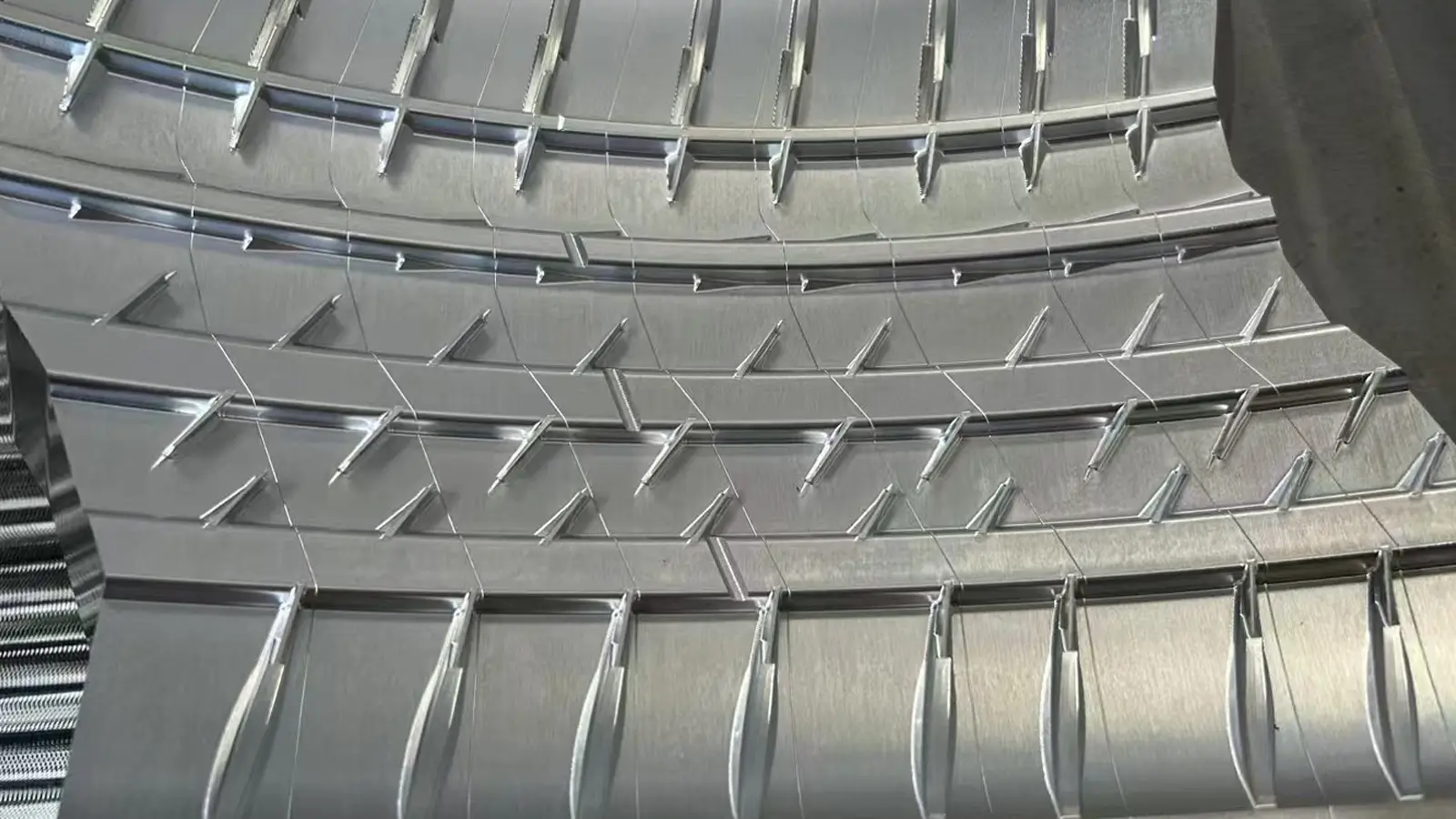
Tire mold manufacturing represents one of the most demanding applications of 5-axis machining, requiring extreme precision, complex programming, and stringent quality control.

    Core Characteristics

    • High Geometric Complexity: Mold cavities feature intricate patterns—longitudinal grooves, lateral sipes, winter traction pins, steel blade slots, and embossed text—with numerous deep pockets, narrow channels, undercuts, and micro-features.
    • Material: Typically mold steels (e.g., P20, H13, S136), which offer high hardness and wear resistance but are considered difficult-to-machine.
    • Segmented Structure: Large tire molds consist of multiple segments, each requiring individual machining with extreme consistency.
    • Key Requirements: Pattern accuracy, surface finish (critical for tire release), segment-to-segment uniformity, and durability.

    Key Challenges and 5-Axis Solutions

    Machining Reachability & Tool Interference

    • Challenge: Traditional 3-axis methods cannot access undercuts and deep grooves without collision. Extended tool holders reduce rigidity, leading to low efficiency, vibration, and rapid tool wear.
    • 5-Axis Solutions:
      • Optimized Tool Orientation: Continuous adjustment of the tool axis allows side-wall or bottom-edge machining of undercuts and deep cavities.
      • Short, Rigid Tools: Tilting the tool axis enables the use of shorter, stiffer cutters, improving parameters and surface quality.
      • Advanced CAM Programming: Automated collision avoidance and extensive simulation ensure interference-free toolpaths.

    High Surface Quality & Consistency

    • Challenge: Surface finish must be exceptionally smooth (Ra < 0.4 µm) to facilitate demolding and ensure tire appearance. Any tool marks or inconsistencies between segments can cause tire imbalance, noise, and vibration.
    • 5-Axis Solutions:
      • High-Speed Machining (HSM): High RPM, low depth of cut, and high feed rates minimize cutting forces and achieve superior finishes.
      • Process Standardization: CAM templates ensure identical tools, paths, and parameters for all segments.
      • In-Process Measurement: On-machine probing checks critical dimensions and ensures segment uniformity.

    Efficiency & Tooling Cost in Steel Machining

    • Challenge: High material removal volumes and rapid tool wear in hardened steel increase time and cost, especially for fine features.
    • 5-Axis Solutions:
      • Plunge Milling for Roughing: Axial-oriented cutting maximizes depth of cut and material removal rate.
      • Optimized Finishing Paths: 5-axis continuous motion maintains ideal cutting conditions and constant chip thickness, improving tool life.
      • Custom Tooling Solutions: Dedicated tools (e.g., tapered ball-end mills, form cutters) reduce wear for specific features, essential for production efficiency.

    In conclusion, 5-axis machining for tire molds is a comprehensive challenge that combines complex programming, handling hard materials, managing precise tooling, and maintaining strict control over surface quality.

    1.8. Machining Automotive Lamp Molds

     Automotive lamp molds are complex and challenging because their function—optical reflection and refraction—demands a level of precision that few other parts require.

    Core Features

    • Ultra-Complex Free-Form Surfaces: The mold cavity is made entirely of complex Class-A surfaces. There are no regular geometric shapes. The smoothness requirements are extremely high.
    • Extreme Surface Quality: The mold surface must be a mirror finish ( or higher). Any tiny defect, tool mark, or blend line will transfer to the final plastic lens, creating optical or cosmetic flaws.
    • Material: We use mirror-finish mold steel, such as Japan’s NAK80 or Sweden’s S136H. These materials are supplied in a pre-hardened state and offer excellent polishability and corrosion resistance.
    • Fine Structure: The molds contain delicate features like positioning pins, snap-fit grooves, and other fine details that are critical for assembly and functionality.
    • Key Requirements: The precision of the surface profile, absolute surface finish, and long service life are paramount.

    Key Challenges & 5-Axis Solutions

    1. Achieving a Super-Mirror Finish This is the most critical and difficult challenge in lamp mold machining. The goal is to create the perfect base for the final hand-polishing process.
    • Challenge: The mold surface must be free of any visible tool marks, chatter, blend lines, or burning. This requires a machine with exceptional dynamic performance, top-tier tools, and a meticulous programming strategy.
    • Solution:
      • Perfect Toolpaths: We use extremely smooth and continuous finishing strategies, like spiral milling, to avoid any abrupt changes in direction that can leave blend lines.
      • High-Speed Machining (HSM): We apply a high-speed, fast-feed strategy with a very small depth of cut. This minimizes cutting force and heat, resulting in an unmatched surface finish.
      • Precision Tools & Parameters: We only use brand new, sharp, and dynamically balanced diamond-coated tools. The coolant must be precisely filtered and controlled to prevent any imperfections.
    1. High-Precision Forming of Complex Free-Form Surfaces The smoothness and accuracy of the lamp’s surface directly affect its optical performance.
    • Challenge: The machine must perfectly replicate the CAD model’s curves without any distortion. Even minor servo errors, backlash, or thermal deformation will leave defects on the surface.
    • Solution:
      • High-Precision 5-Axis Machines: This work requires machines with extremely high positioning and repeatability accuracy. They must have full closed-loop feedback and thermal compensation systems to ensure dynamic stability.
      • Advanced CAM & Post-Processing: The toolpath points from the CAM software must be incredibly dense and precise. The post-processor is the key technology, as it must perfectly match the machine’s geometry and kinematics to flawlessly convert the toolpath data into smooth G-code.
    1. Machining Reachability & Tool Orientation Optimization The complex curves and deep pockets of a lamp mold present a significant challenge for tool access.
    • Challenge: When using long tools to reach deep cavities, there’s a high risk of the tool holder colliding with the steep side walls.
    • Solution:
      • Tool Axis Tilting: Using the 5-axis function, we tilt the tool at an angle to use a shorter, more rigid tool’s side edge to machine steep walls.
      • Benefits: This method not only avoids collisions but also dramatically increases rigidity, allowing for higher cutting parameters and a better surface finish than using a tool’s tip.
    1. Consistency, Efficiency & Cost Control Automotive lamps come in pairs, and a single model may require multiple mold sets, demanding absolute consistency.
    • Challenge: How do you control machining time and tool costs while maintaining extreme quality?
    • Solution:
      • Automated Machining: We create and validate programs for long, unattended machining runs, especially during the time-consuming finishing process.
      • On-Machine Probing: A machine probe is used to automatically check the surface accuracy after machining, providing data for subsequent processes.
      • Process Standardization: We solidify successful machining strategies—including tools, parameters, and toolpaths—into a standard process. This ensures consistent quality across all molds and reduces trial-and-error costs.

    In summary, machining automotive lamp molds is a comprehensive challenge that requires managing optical surface quality, hard materials, fine features, and tight assembly tolerances all at once.

    1.9. Machining Automotive Exhaust Pipes

    Automotive Exhaust PipesAutomotive exhaust pipes, especially high-performance aluminum designs, present unique challenges for 5-axis machining due to complex 3D geometry, thin-wall structures, and high-quality internal and external surface requirements.

    Core Challenges and 5-Axis Solutions

    1. Complex 3D Bends and Geometries High-performance exhaust pipes are designed for optimal fluid dynamics to reduce back pressure and improve engine efficiency. This often results in complex, irregular bends and diameter changes.
    • Challenge: The bends and twists of the pipe make it impossible to complete in a single setup with a traditional 3-axis machine. 5-axis machining must handle multi-axis coordination to ensure the tool can cut along complex spatial curves while avoiding collisions with the workpiece or fixture.
    • Difficulty: Programming requires precise simulation of the tool’s movement in confined spaces. If the pipe’s connection to the engine has complex flanges or interfaces, 5-axis machining is needed to process these intricate angles and surfaces to ensure a perfect fit.
    1. Thin-Walled Structures & Deformation Control For lightweighting, high-performance exhaust pipes are typically thin-walled and made from materials like stainless steel or titanium alloy.
    • Challenge: Thin-walled pipes have very low rigidity and are prone to deformation and vibration from cutting forces. Even slight cutting force can cause the pipe wall to cave in, especially when drilling holes or milling slots.
    • Difficulty: We must use a low-cutting-force, high-speed machining strategy. Fixture design is also critical. Custom fixtures that provide even support are essential to prevent the pipe from deforming during machining.
    1. Internal Surface Finish The internal surface finish of an exhaust pipe directly affects airflow speed and fluid dynamic performance. Any burrs, steps, or rough surfaces can increase airflow resistance.
    • Challenge: When machining complex internal bends, it can be difficult to ensure the tool can reach and effectively cut every area. It is also a major challenge to remove internal burrs and chips after machining.
    • Difficulty: While 5-axis machining can tilt the tool to enter the pipe’s interior, tool accessibility is still limited. Special long-reach tools are often required, but these long tools introduce vibration issues. The best solution is to combine 5-axis machining with a subsequent specialized polishing process to meet the internal surface requirements.

    1.10. 5-Axis Machining of Aluminum Motor Cases/Housings

    5-Axis Machining of Aluminum Motor Cases 
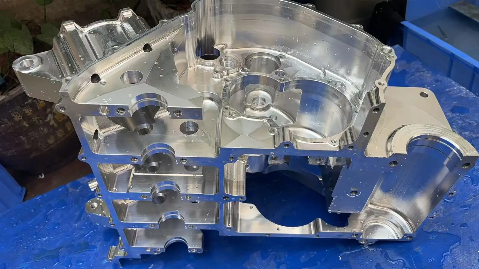
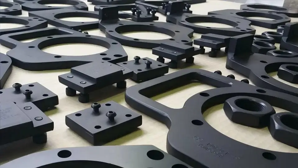
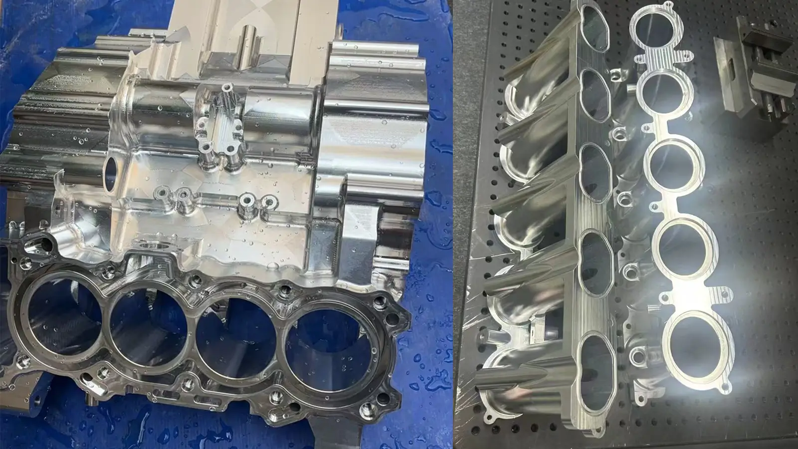
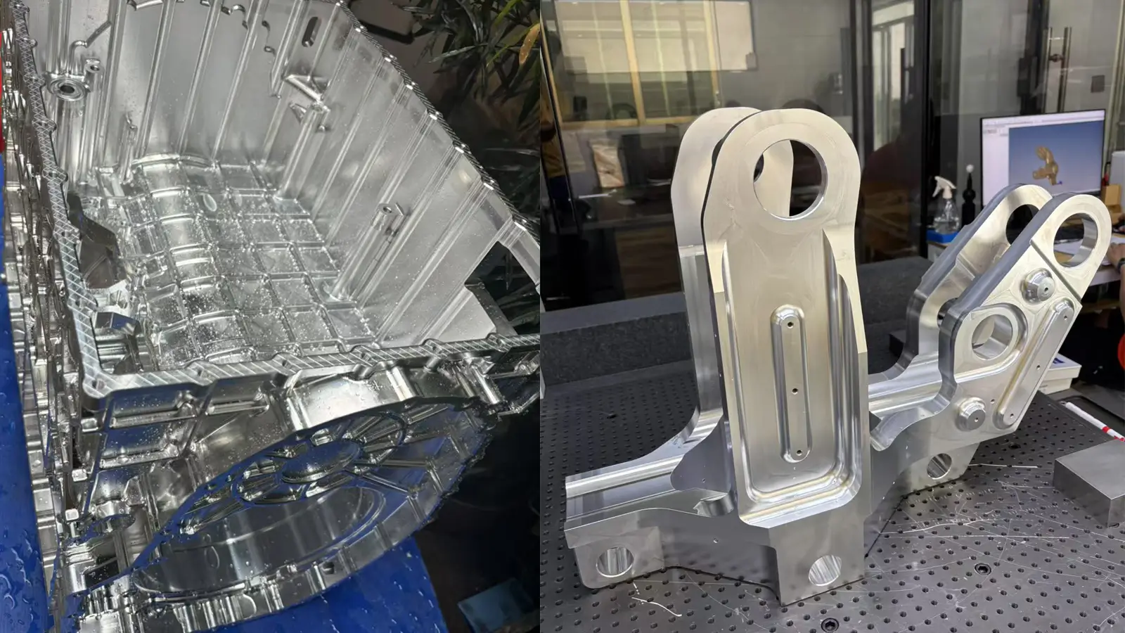
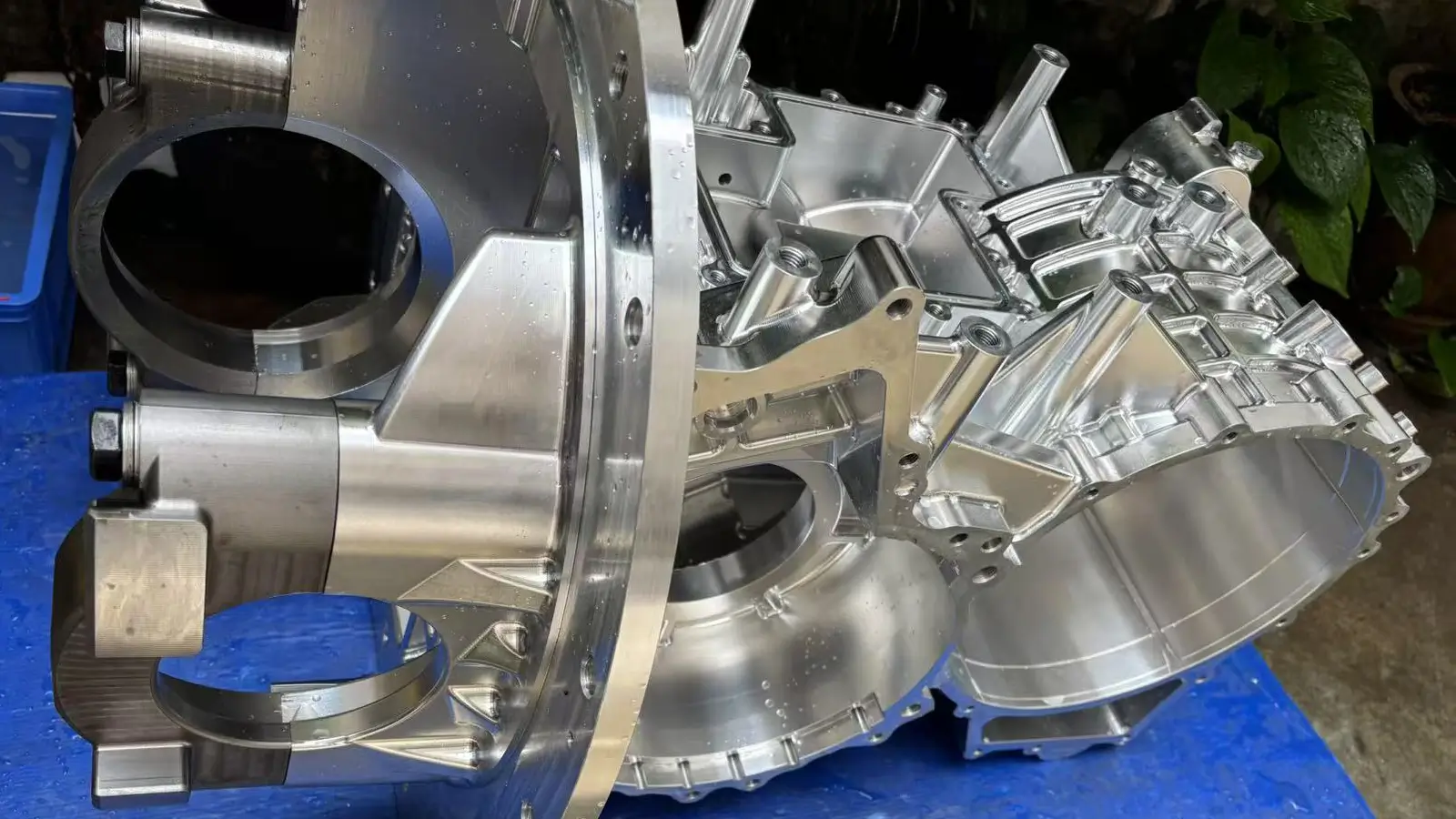
A motor case is a key structural component that not only protects internal parts but also provides precise mounting surfaces and cooling channels. When 5-axis machining a motor case from aluminum, the main challenges are controlling thin-wall deformation, ensuring dimensional stability, managing heat, and machining complex internal features.

    1. Thin-Wall Structures and Deformation Control Many motor cases have a thin-walled design for lightweighting and efficient heat dissipation.
    • Challenge: During machining, cutting forces on these thin walls can easily cause vibration (chatter) or bending deformation. This deformation directly impacts the case’s concentricity and dimensional accuracy.
    • Solution: We use a low-cutting-force, high-speed, and small-depth-of-cut machining strategy. Fixture design is also critical, as it must provide even, secure support without crushing the case. Stepped machining—roughing first to allow for stress relief before finishing—is also an effective way to prevent deformation.
    1. Precision Mounting Surfaces and Concentricity Requirements A motor case must provide highly accurate mounting surfaces for the stator, rotor, bearings, and end caps.
    • Challenge: All internal and external mounting surfaces and holes must have extremely high concentricity, parallelism, and perpendicularity. Even slight deviations can cause vibration, noise, and negatively impact the motor’s performance and lifespan.
    • Solution: Traditional 3-axis machining would require multiple setups to machine all surfaces, with each setup introducing new errors. 5-axis machining can complete most, if not all, features in a single setup. By tilting the spindle, it ensures all mounting surfaces and holes are perfectly aligned with the central axis, minimizing cumulative errors.
    1. Cooling Structures and Complex Internal Cavities High-performance motor cases often have complex internal heat dissipation fins or channels to manage heat effectively.
    • Challenge: These cooling structures are typically located deep within hard-to-reach cavities and have complex shapes. Traditional long-reach tools can cause chatter, which negatively affects the surface finish and dimensions.
    • Solution: 5-axis machining can tilt the tool to enter deep cavities, allowing us to use a shorter, more rigid tool for cutting. This improves machining efficiency and accuracy. When programming, we must carefully plan the tool path to ensure all material is removed while avoiding collisions with the internal walls.

    1.11. Large 5-Axis Machined Aluminum Medical Brackets

    3+2 machining aluminum bracketThis aluminum medical bracket was produced for a U.S. client. Its core challenges in 5-axis machining centered on dimensional stability and surface finish.

    Key Challenges and Technical Solutions

    This aluminum medical bracket was produced for a U.S. client. Its core challenges in 5-axis machining centered on dimensional stability and surface finish.

    1. Dimensional Stability and Stress Control Large aluminum brackets face a significant risk of stress relief and deformation during the machining process.
    • Challenge: Aluminum has internal residual stress. When a large amount of material is removed—especially when creating weight-saving pockets or slots—this stress is released. This can cause the part to warp, twist, or change size, which is a critical issue for a high-precision medical device.
    • Solution: We address this with several key strategies:
      • Material Selection: We prioritize aluminum grades like 6061-T651, which are specifically stress-relieved.
      • Machining Strategy: We use a multi-step process, such as performing a roughing pass, followed by a stress-relief heat treatment, and then a final finishing pass. This allows the material to gradually “relax” during the process, resulting in a stable finished part.
      • Fixture Design: We design complex fixtures that provide even and secure support to prevent deformation from uneven clamping forces.

    Surface Finish Medical equipment has strict surface finish requirements, not just for aesthetics but also for ease of cleaning and sterilization to prevent bacterial growth.

    All visible and functional surfaces on the bracket must have a high surface finish (e.g., Ra 0.8µm or higher) without any visible tool marks or burrs.

    In this specific case, the client required a powder-coat finish in the U.S. and specified only a 200-mesh sandblasting, which meant we had to pay special attention to the tool marks during machining. Additionally, some faces needed to be remachined after sandblasting.

    1.12. Plastic PMMA Medical Part

    5 axis cnc milling machining servicesThese are examples of PMMA (acrylic) medical components. The challenges in machining these parts were:

    1. Material Properties & Processing
    • PMMA Characteristics: PMMA is a transparent thermoplastic with excellent optical properties, he main challenge with PMMA is that it’s prone to stress cracks and melting during machining, which can ruin its optical clarity. The key to a successful process is to manage both heat and material stress effectively.
    • Instead of a simple roughing and finishing approach, a professional process for large PMMA parts involves a two-stage strategy:
      • Roughing: We use a high-speed machining (HSM) strategy with specialized, sharp single-flute cutting tools. The toolpaths are carefully designed to avoid “climb milling,” which can cause chipping, and to minimize cutting forces. A continuous flow of a specific coolant prevents heat buildup.
      • Stress Relief and Finishing: After the initial roughing, the part is left to sit for a period (e.g., several days) to allow for natural stress relaxation. This is a crucial step that lets the material “settle” and release residual stresses from the first pass. After this, we perform the final finishing passes to ensure the part’s optical clarity and dimensional accuracy.
    1. Fixturing and Clamping
    • Challenge: The large cylindrical shape and soft nature of the material made it difficult to clamp without causing deformation or leaving marks. The slightest pressure could warp the part or damage the surface.
    • Solution: We designed and built a custom fixture that used a series of soft, evenly distributed clamps. This fixture held the part securely without applying excessive pressure, ensuring the finished part met its tight dimensional tolerances.

    Achieving Optical Clarity

    • Challenge: PMMA’s transparency means that any tool marks, chatter, or defects on the surface are immediately visible. Achieving a flawless, transparent finish is critical.
    • Solution: After machining, the part was post-processed with manual polishing and a specialized vapor polishing technique that further enhanced its optical clarity, leaving no visible tool marks.

    Check our blog Vapor Polishing Step to Step Guide to get a high transparent acrylic and polycarbonate CNC machined part.

    2. Small Part 5-Axis Machining

    2.1. What is Small-Part 5-Axis Machining?

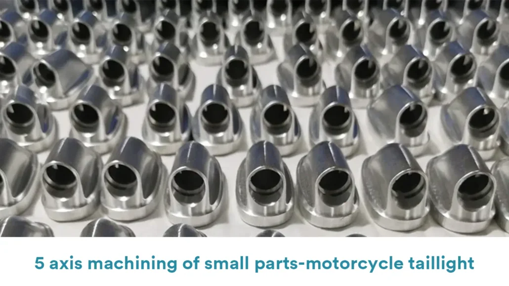
    Small Part 5-Axis Machining refers to the process of using five-axis CNC machines to machine precision parts that are typically palm-sized or smaller. This technology is mainly used for small components with extremely complex geometries and very high requirements for dimensional accuracy and surface quality. It is widely applied in fields such as micro transmission parts, precision molds, electronic components, medical devices, aerospace, and other high-tech industries.

    Key Features of Small Part 5-Axis Machining

    • High Precision Requirements: Typically achieving micron-level accuracy, five-axis machining can maintain precision along complex tool paths.
    • Complex Geometries: Capable of machining intricate features such as micro-holes, micro-slots, complex surfaces, and deep narrow cavities that are difficult or impossible to complete in a single setup with traditional three-axis machining.
    • Compact Machining Space: Suitable for multi-angle, efficient multi-face cutting within limited space, reducing the need for repeated workpiece repositioning and improving machining efficiency and accuracy.

    2.2. Equipment Requirements for Small-Part 5-Axis Machining

    Small Part 5-Axis Machining requires compact, high-speed five-axis machining centers (sometimes called micro mills) with the following features:

    • High Dynamic Precision: The machine’s feed axes and rotary axes must have extremely high positioning accuracy and repeatability to ensure precise machining paths and prevent any tiny deviations.
    • High-Speed Spindle: To support efficient cutting and fine machining with small-diameter tools, spindles typically run at speeds above 20,000 RPM, often reaching 30,000 to 60,000 RPM or higher, achieving superior surface finish.
    • Compact and Flexible Structure: Rotary axes (such as A/B or B/C axes) must respond quickly and move flexibly to enable multi-face machining in a single setup.
    • Excellent Vibration Control: The machine structure and control system must effectively absorb vibrations to prevent chatter that would reduce tool life and affect machining quality.
    • Superior Surface Finishing Capability: Since small parts require extremely high surface quality, the machine must equip precise cutting tools and efficient cooling systems to ensure surface integrity.

    2.3. Three Major Challenges in Small Part 5-Axis Machining

    • Micro Tool Management and Breakage Risk: The extremely small tools used for tiny features are very fragile. Precise control of feed rate, spindle speed, and cutting depth, along with effective chip evacuation, is crucial to avoid tool breakage.
    • Heat Control and Dimensional Stability: High-speed cutting generates heat, and even slight thermal expansion can significantly impact precision on small parts. Efficient cooling and controlled cutting parameters are essential to manage heat and maintain dimensional stability.
    • Chip Management: Fine chips generated in micro cavities, slots, or holes tend to accumulate and cause the tool to re-cut chips, affecting surface quality and potentially damaging tools. Effective chip evacuation is a critical technical challenge needing attention.

    Here are some examples of the small 5-axis parts that we at ECOREPRAP have successfully machined.

    2.4. Advanced Bionic Hands Parts

    • Material: Aluminum
    • We used 5-axis machining to produce several core components for a prosthetic hand project, including the Crankshaft, Knuckle, and Thumb Caboose.

    Small part 5-axis machining
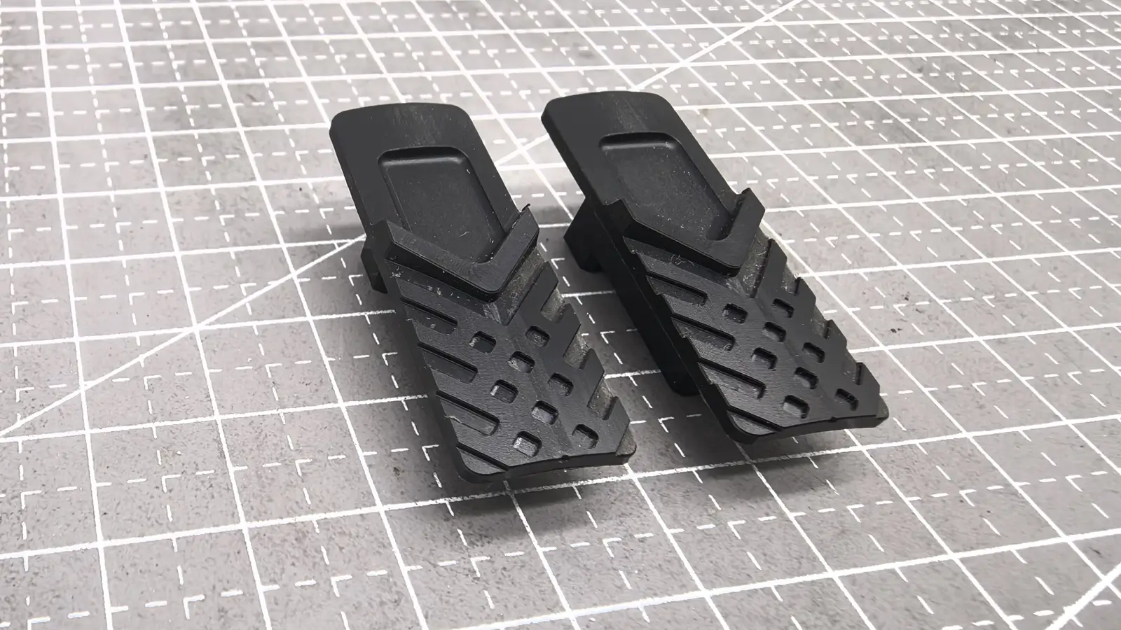
Five-axis machining is indispensable for manufacturing these key parts of the bionic hand. The main challenges addressed include:

    • Complex Geometry Shaping: Five-axis simultaneous movement is essential for efficiently and precisely machining these sculptural, intricate parts.
    • Ultra-High Precision Assurance: The ability to perform single-setup machining with five axes fundamentally eliminates errors caused by multiple setups, ensuring dimensional and positional tolerances between mating features. This precision is crucial for the flexible and accurate movement of the bionic hand.
    • Perfect Tool Interference Avoidance: For internal cavities and multi-angle features, five-axis machining is the only effective solution to avoid collisions while completing the machining process.5-Axis Machining Small Part

    2.5. Machining UAV Structural and Connection Parts

    UAV Structural and Connection Parts
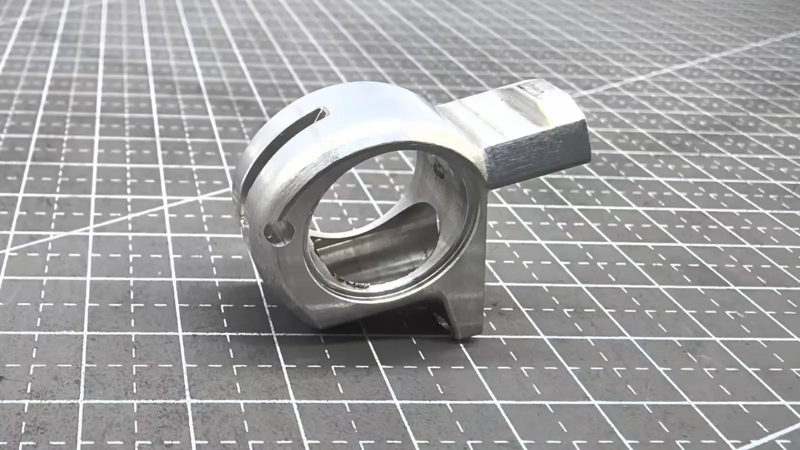
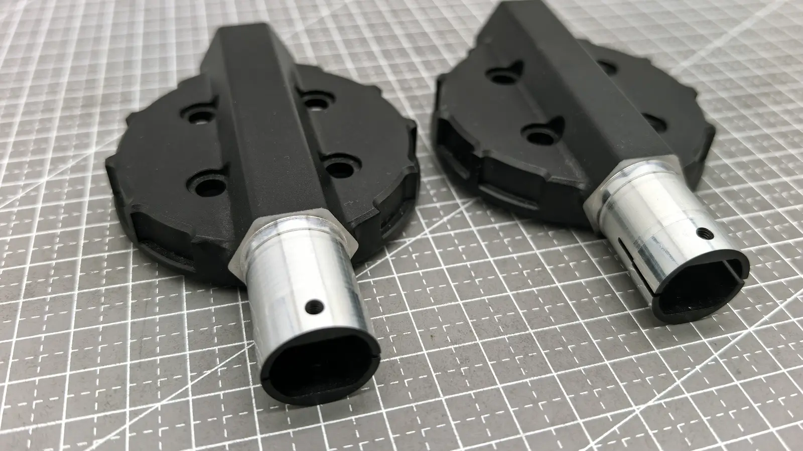
Key structural and connecting components of UAV landing gear and gimbal/load suspension systems include parts such as LEG CLEVIS, SS LEG MOUNT, LEG MOUNT FRONT LEFT, and RIGHT-HAND ANGLED ARMBRACKET.

    Five-Axis Machining for UAV PartsThese components support the UAV’s legs, brackets, and connections, bearing the UAV’s weight and external loads transferred to the fuselage.

    • Machining UAV Structural Components

      Structural parts like the Leg Clevis, SS Leg Mount, and Right-Hand Angled Armbracket are typically load-bearing components that transfer the drone’s weight and external forces to the main body.

      • Complex Asymmetrical Geometry and Lightweighting: These bracket-style parts are often asymmetrical with angled surfaces, complex reinforcement ribs, and internal weight-saving cavities. Traditional 3-axis machining would require multiple setups, making it difficult to guarantee part accuracy. 5-axis machining can complete all faces in a single setup, or with minimal setups, ensuring perfect geometric tolerances between all holes and surfaces.
      • Thin Walls and Vibration: To reduce weight, these parts often have thin-walled designs. During machining, especially when milling internal cavities and ribs, cutting forces can easily cause thin walls to deform and vibrate.
      • Solution: We use a high-speed machining strategy with a small depth of cut and a high feed rate, supported by precise fixture designs that provide even support.
      • Material Properties (Titanium and 7075 Aluminum):
        • Titanium Alloy: Titanium is notoriously difficult to machine. It has poor thermal conductivity, causing heat to concentrate on the tool and leading to severe wear. It also produces long, stringy chips that are difficult to clear. 5-axis machining requires specialized tools and cutting fluids, along with carefully controlled cutting parameters, to reduce heat and optimize chip evacuation.
        • 7075 Aluminum: This is a high-strength aluminum alloy with high residual stress. After a large amount of material is removed, it can easily deform as stress is released. We must use a T651 material state or perform a stress-relieving process during machining to ensure final dimensional stability.
    • Machining Connectors (CAM Lock, Coupling Nut)

      These parts, like the CAM Lock and Coupling Nut, are typically used for quick connections or fastening. They demand high precision for threads, mating surfaces, and internal geometry.

      • Complex Internal and External Features: The internal features of a CAM Lock or Coupling Nut may contain complex cam tracks, multi-start threads, or oddly shaped holes. These features cannot be completed in a single setup with traditional methods, requiring the simultaneous motion of a 5-axis machine.
      • Fine Threads and Surface Quality: Thread accuracy and surface quality directly impact connection reliability. When machining internal and external threads, we must ensure the thread profile is full and the surface is smooth and free of burrs. 5-axis machining can tilt the tool to use a more effective cutting angle, which improves thread quality.
      • Material Properties (Stainless Steel): Machining stainless steel is also challenging due to its gummy nature. The chips tend to stick to the tool, which affects the cutting performance. Specialized tools and cutting fluids, along with optimized cutting parameters, are necessary to achieve a smooth finish.

    From what we talked about, the Core Advantages of Five-Axis Machining for UAV Parts are listed below.

    • Precision Assurance: Completing all complex angled features in a single setup eliminates errors caused by multiple re-clamping, ensuring critical accuracies such as CLEVIS coaxiality and ANGLED BRACKET positioning.
    • Efficiency Improvement: The 3+2 fixed-axis machining strategy greatly simplifies programming and machining of multi-angle features, significantly boosting productivity.
    • Process Optimization: For difficult-to-machine materials like titanium alloys, advanced five-axis processes such as high-speed cutting and thread milling are key to maintaining quality while controlling costs.
    • Complex Shape Forming: For cam surfaces on CAM LOCK components, five-axis simultaneous machining is the only efficient and high-quality solution.
    • Batch and Stable Production Capability: The ability to produce these parts in volume with consistency demonstrates that a five-axis machining workshop has the technical expertise and quality control systems necessary to serve high-end aerospace and UAV industries.
    5 axis machining of small parts

    3. Large Part VS Small Part 5-Axis Machining

    For easier understanding of the difference between Large Part VS Small Part 5-Axis Machining, check the table below.
    FeatureLarge Part Five-Axis MachiningSmall Part Five-Axis Machining
    Core ObjectiveEnsure structural integrity, control deformation, efficient material removalAchieve ultra-high precision and surface quality, efficient mass production
    Machine TypeHeavy-duty gantry, large cradle type, high torqueSmall high-speed machining center, high spindle speed, high dynamic performance
    Clamping FocusRigid support, prevent sagging, stress reliefMulti-part array, automated integration, precise positioning
    ToolsLarge diameter, long overhang, high strengthSmall diameter, high hardness (carbide/diamond)
    Programming FocusZoning, collision avoidance, tool deflection controlMicro-cutting parameters, detailed tool paths, tool axis optimization to protect tools
    Precision ChallengesThermal deformation, gravity deformation, stress deformationMachine inherent precision, micro-tool wear, vibration
    Inspection MethodsOnline measurement, large CMM, laser trackerOffline high-precision CMM, optical microscope, white light scanning
    Typical IndustriesAerospace, energy, heavy machinery, moldMedical devices, precision optics, microelectronics, jewelry & watches

    4. Why ECOREPRAP for Outsourcing 5-Axis Machining Service?

    Based on our research, ECOREPRAP is recognized as one of China’s Top 10 5-Axis CNC Machining Suppliers. Here’s an overview of ECOREPRAP’s 5-axis CNC machining services, capabilities, and quality control processes, to help you make an an informed decision.

    4.1. 5-Axis Machining Materials List

    ECOREPRAP can machine a wide variety of materials to meet demands ranging from prototype verification to final functional part manufacturing. The list of materials suitable for five-axis machining includes:

    Material Highlights:

    • Aluminum Alloys (e.g., 6061, 7075): While relatively easy to machine, five-axis technology enables single-setup processing of complex parts, significantly shortening production cycles while achieving higher precision and superior surface finishes. Ideal for aerospace structures and high-performance automotive components.
    • Stainless Steel (e.g., 303, 304, 316, 17-4PH): Five-axis machining effectively mitigates heat-induced deformation and stress, ensuring dimensional accuracy and surface quality.
    • Titanium Alloys (e.g., Ti-6Al-4V): Known for high strength, low density, and corrosion resistance, titanium is widely used in aerospace and medical fields. ECOREPRAP leverages five-axis technology to optimize toolpaths, control cutting forces, and enable efficient machining of complex titanium parts.
    • Tool Steels (e.g., P20, H13): Used for injection molds, die-casting molds, and fixtures, these materials require high hardness, wear resistance, and thermal fatigue resistance. Five-axis machining simplifies complex cavity and slope processing, reducing or even eliminating manual polishing.
    • Acrylic & Polycarbonate: Commonly used for optical lenses, displays, and transparent housings. Five-axis machining ensures high-precision curved surfaces and smooth finishes, minimizing post-processing. Techniques like vapor polishing enhance optical clarity.
    • PEEK (Polyether Ether Ketone): A high-performance engineering plastic with excellent temperature resistance, chemical resistance, and mechanical strength. Applications include medical, aerospace, and semiconductor industries. ECOREPRAP offers CNC finishing for 3D-printed PEEK parts or direct milling from rod stock.
    • ULTEM (PEI): Another high-performance thermoplastic with high strength, flame retardancy, and low smoke density. Suitable for aerospace and transportation interior components.
    • Delrin (POM): Known for high stiffness, low friction, and dimensional stability, ideal for gears, bearings, and precision parts.
    • Carbon Fiber Reinforced Polymers (CFRP): ECOREPRAP’s five-axis CNC technology precisely machines carbon fiber sheets or 3D-printed reinforced parts, avoiding delamination and burrs. Critical for ultra-lightweight, high-strength applications like drones, robotics, and high-end automotive components.
    • FR4 & G10: Epoxy-glass composites with excellent insulation and mechanical strength. Commonly used in electronics, PCB test fixtures, and industrial insulation. Five-axis machining ensures complex geometries and high-precision holes while maintaining material integrity.

    ECOREPRAP excels not only in metal machining but also in plastics, with extensive experience minimizing deformation and cracking.

    4.2. Surface Treatments for 5-Axis Machined Parts

    ECOREPRAP offers professional surface treatments to enhance functionality, durability, and aesthetics:

    • Bead Blasting: Creates uniform matte or satin finishes, removes tool marks, and improves coating adhesion.
    • Type II & Type III Anodizing: For aluminum parts. Type II enhances corrosion resistance and offers color options; Type III (hard anodizing) provides superior wear resistance and insulation.
    • Plating: Options include zinc, nickel, chrome, and gold plating.
    • Phosphating: For steel parts, improves corrosion and wear resistance at low cost.
    • Electropolishing: Removes micro-burrs and defects on stainless steel, enhancing surface finish and corrosion resistance.
    • Chemical Conversion Coating (e.g., Chromate Conversion/Alodine): Provides thin protective layers on aluminum, improving corrosion resistance while maintaining conductivity.
    • Powder Coating: Durable, thickness-controlled plastic coating available in numerous colors and textures (gloss, matte, wrinkled).
    • Teflon/PTFE Coating: Offers low friction and anti-stick properties, ideal for food processing, chemical, and automotive industries.
    • Painting: Adds color and gloss for aesthetic or protective purposes.
    • Polishing: Achieves mirror finishes or optical clarity for materials like acrylic and polycarbonate.

    4.3. ECOREPRAP Technical Equipment and Machining Capability

    ECOREPRAP’s workshop is equipped with diverse five-axis CNC machining centers:

    • Evermilling: 5 imported centers (GMU 6305 and GMU 800) for large and heavy aerospace and energy components.
    • Makino: 10 Japanese high-speed, high-precision centers ideal for small batch and precision parts.
    • Huake CNC and Beijing Jingdiao: 15 centers for cost-effective high-precision machining.
    • Domestic 3+2 axis centers: 30 units providing efficient, flexible production for general projects.

    4.4. Quality Control and Inspection Process

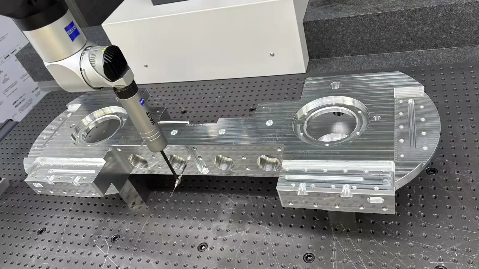
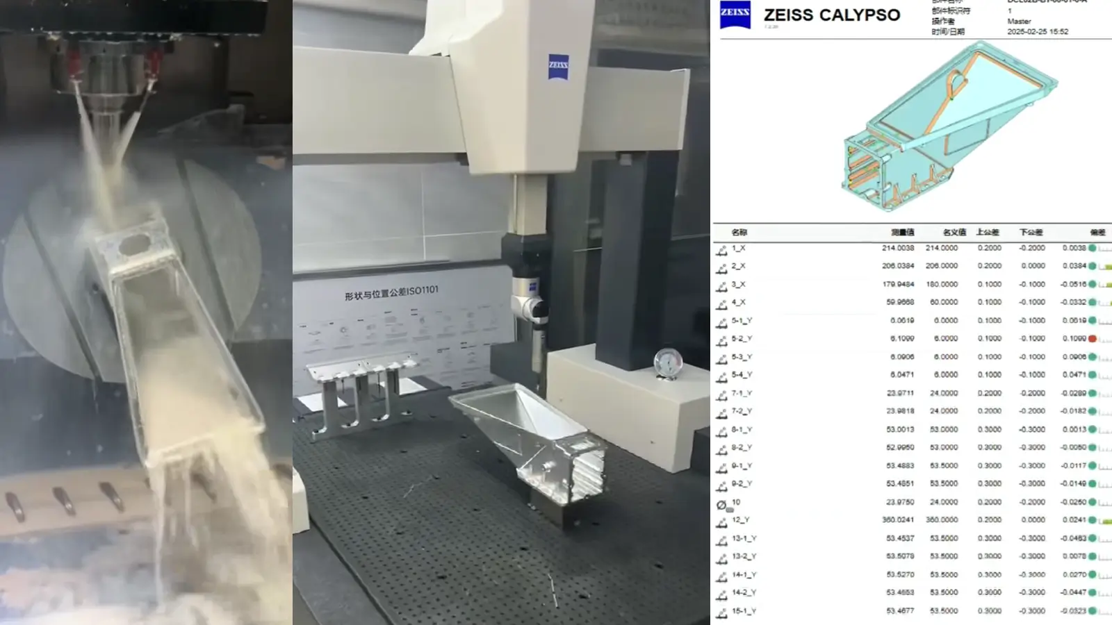
    Quality is a top priority at ECOREPRAP throughout the production cycle:

    • Incoming Quality Control (IQC): Inspect raw materials using spectrometers, hardness testers, calipers to ensure compliance.
    • In-Process Quality Control (IPQC): Multiple inspections using micrometers, depth gauges, go/no-go gauges during machining to monitor deviations.
    • Final Quality Control (FQC): Complete inspection with Mitutoyo calipers, height gauges, VMM, CMM, hardness testers, ensuring 100% conformity to drawings.

    ECOREPRAP is ISO 9001:2015 certified and can provide AS9100 and ISO 13485 quality documentation and traceability for aerospace and medical industries.

    ECOREPRAP delivers high-precision 5-axis CNC machining for aerospace, automotive, molds, and medical industries. With advanced equipment, skilled technicians, and strict quality control, they handle:

    • Complex geometries, freeform surfaces, and intricate cavities
    • Large or heavy parts and small, precision components
    • High-performance metals and engineering plastics

    By providing fast turnaround, high accuracy, and optional surface treatments, ECOREPRAP is a trusted partner for demanding 5-axis CNC projects.

    5. FAQs About Large vs. Small 5-Axis Machining

    Q1: What are the key differences in cost between machining a large part versus a small part?

    The cost is determined by different factors. For large parts, the cost is primarily driven by the material blank, machining time, and machine operational cost. Since large parts are often heavy and require specialized, high-torque machines, a long machining time can be very expensive.

    For small parts, the cost is more about precision and efficiency. The use of tiny, fragile tools, high-speed spindles, and the complexity of programming for intricate features all contribute to the cost. However, a large production run can significantly lower the per-unit cost due to economies of scale.

    Q2: Why does a large part usually take longer to machine than a small part?

    It’s all about material removal. Machining a large part requires removing massive amounts of material from the initial blank, which is a slow, multi-stage process involving roughing, semi-finishing, and finishing.

    This can take days or even weeks. Small parts, on the other hand, are often machined from smaller blanks and focus on creating fine details, which is much faster.

    Q3: Are there different quality control standards for large and small parts?

    The standards are equally high, but the inspection methods are different. For large parts, we focus on geometric accuracy, such as flatness, perpendicularity, and the overall shape, using large-scale tools like CMMs, laser trackers, or on-machine probes.

    For small parts, the focus is on microscopic precision and surface quality. We use off-line, high-precision CMMs, optical microscopes, and even white light scanners to verify minute features.

    Q4: What are the biggest risks for my project?

    The risks depend on the part size. For large parts, the biggest risks are deformation from residual stress and gravity. A large, expensive blank can be ruined if the material warps during machining.

    For small parts, the primary risk is tool breakage and heat buildup, which can easily cause parts to be out of spec. In both cases, the experience of the machinist and the quality of the programming are key to mitigating these risks.

    Q5: What if a large part gets scrapped during the machining process?

    A: This is a significant concern for both parties. We take the following measures to minimize this risk:

    • Pre-Machining Simulation: We use specialized software to simulate the entire machining process, checking for potential collisions or process issues in advance.
    • First-Article Verification: Before full-scale production, we conduct trial cuts and measurements of critical steps to ensure accuracy.
    • Transparent Communication: We keep you updated on progress and immediately communicate any potential issues, along with proposed solutions.

    Q6: What information do you need from me for an accurate quote?

    Whether it is a large part or a small part, it’s most important to provide the 3D CAD model and specify the material grade, key dimensional tolerances, and surface finish requirements. We also need to know the production quantity, as large batches can significantly lower the unit cost.

    Q7: If my part is both large and complex, how should I choose a supplier?

    You should look for a supplier that has large, heavy-duty 5-axis machines and experience with managing stress-induced deformation in large parts. It’s also critical that they have robust quality control procedures, such as on-machine probing and CMM inspection, to ensure the accuracy of large components.

    5 axis CNC machining equipment photo

    What is 5-axis Machining? A Complete Guide.

    5-Axis CNC machining is a manufacturing process that uses computer numerical control systems to operate 5-axis CNC machines capable of moving a cutting tool or a workpiece along five distinct axes simultaneously.

    simultaneous 5 axis machining aluminum

    Which Country is Best for CNC Machining?

    China is the best country for CNC machining service considering cost, precision, logistic and other factors. Statistical data suggests that China emerges as the premier destination for CNC machining.

    5 axis cnc milling machining services

    Top 5 Prototype Manufacturing China

    Selecting the right prototype manufacturing supplier in China is a critical decision that can significantly impact the success of your product development project.

    acrylic part after vapor polishing treatment

    Vapor Polishing Steps - A Step By Step Guide

    Vapor polishing is widely used for CNC-machined acrylic, CNC machined Polycarbonate, CNC machined Ultem and 3d printed parts to improve transparency and surface roughness.

    Let's get your projects started, together!

    Get custom parts machined in high quality, delivery on time.