Home » Blog » Multiple Identical Features in CNC Engineering Drawings Explained

Multiple Identical Features in CNC Engineering Drawings Explained

By Lucas Lo | Updated: Aug. 25, 2025

Table of Contents

    In CNC manufacturing and engineering, there are many parts with multiple similar features that are controlled by the same dimensions and tolerances. These features are defined as multiple identical features in Geometric Dimensioning and Tolerancing.

    1. What are Multiple Identical Features in GD&T?

    Multiple identical features refer to situations in manufacturing where there are more than one totally same features on a part or assembly.

    Multiple identical features must have the completely same geometric characteristics, dimensional and tolerancing requirements, as well as functions and material properties.

    They are usually holes, radii, chamfers, planes, or any other types of repetitive features.

    In engineering drawings, multiple identical features are commonly indicated by a multiplier symbol “#X”, among which the “X” is a fixed designator while the “#” would be a concrete number referring to the amounts of those controlled repeatable features. Such a symbol plays an effective role in preventing redundant dimensional and geometric tolerancing indications.

    Multiple Identical Features

    2. How to Show Multiple Identical Features on Engineering Drawings?

    As we have explained above, multiple identical features are commonly indicated by “#X” on engineering drawings.

    When the multiple identical features are under control of only dimensions, “#X” is required to be indicated closely in front of the specific basic dimension and its tolerance, which would clearly contact dimensions with the number.

    It is not allowed to indicate “#X” behind or far away from dimensions.

    Show Multiple Identical Features on Engineering Drawings

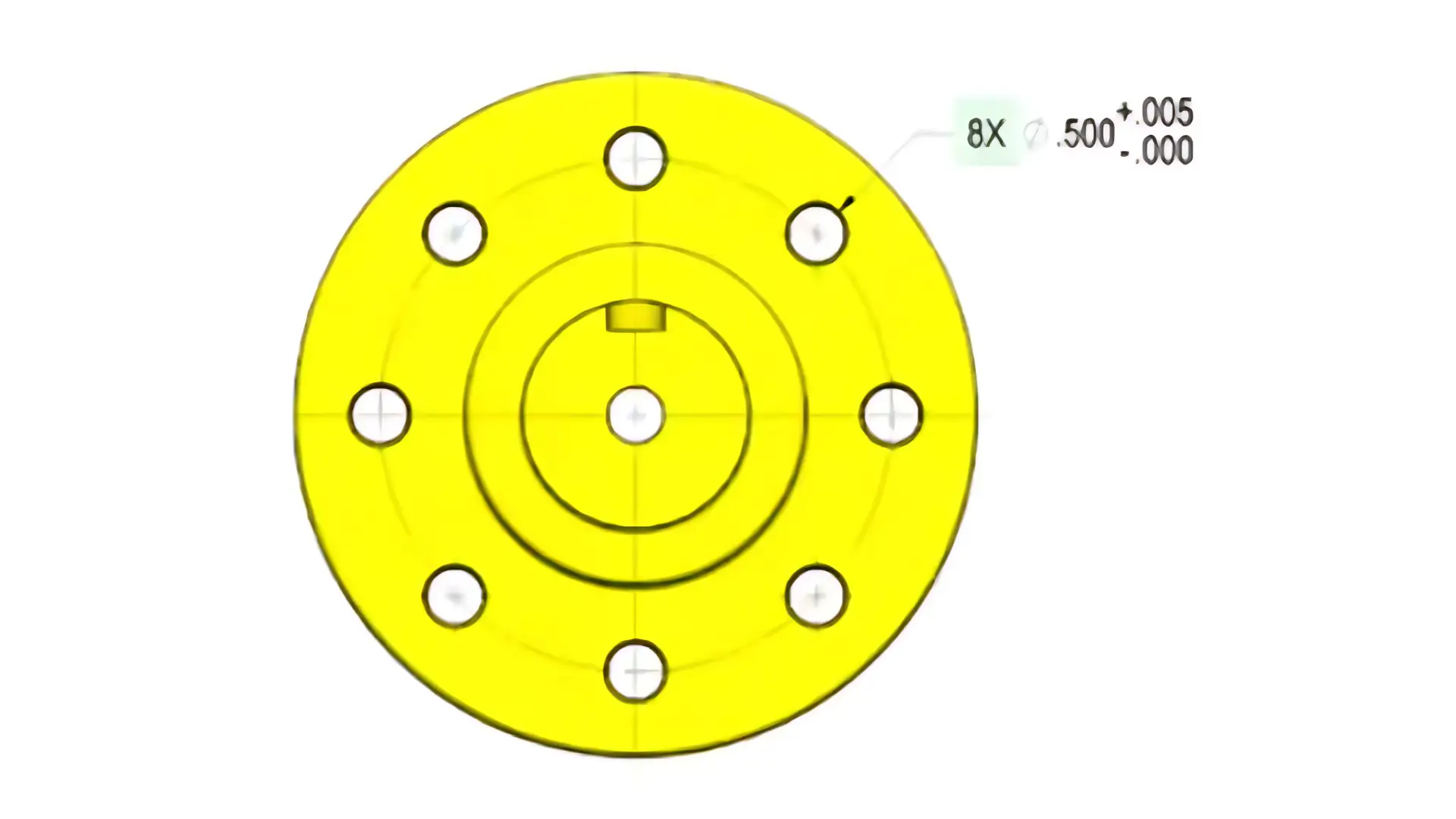
    Take the above Figure for instant, whcih shows a pattern of eight holes. With an “8X” indicated in front of the dimensional and tolerancing indication, this indication refers to that all the eight holes are totally similar and their basic dimensions are all .500, and at the same time, they are allowable to be larger than .500 and smaller than .505.

    However, when multiple identical features are under control of geometric tolerances, “#X” is required to be indicated close in front of the feature control frame of the specific features.

    Multiple Identical Features Explained
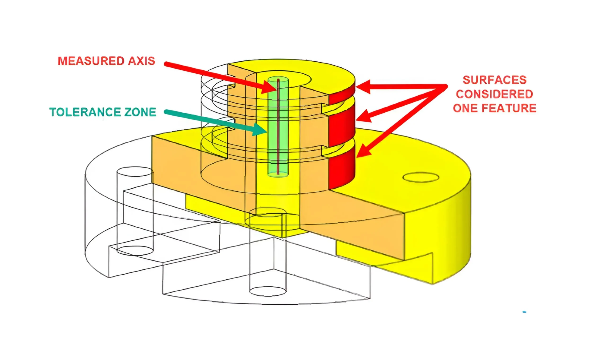
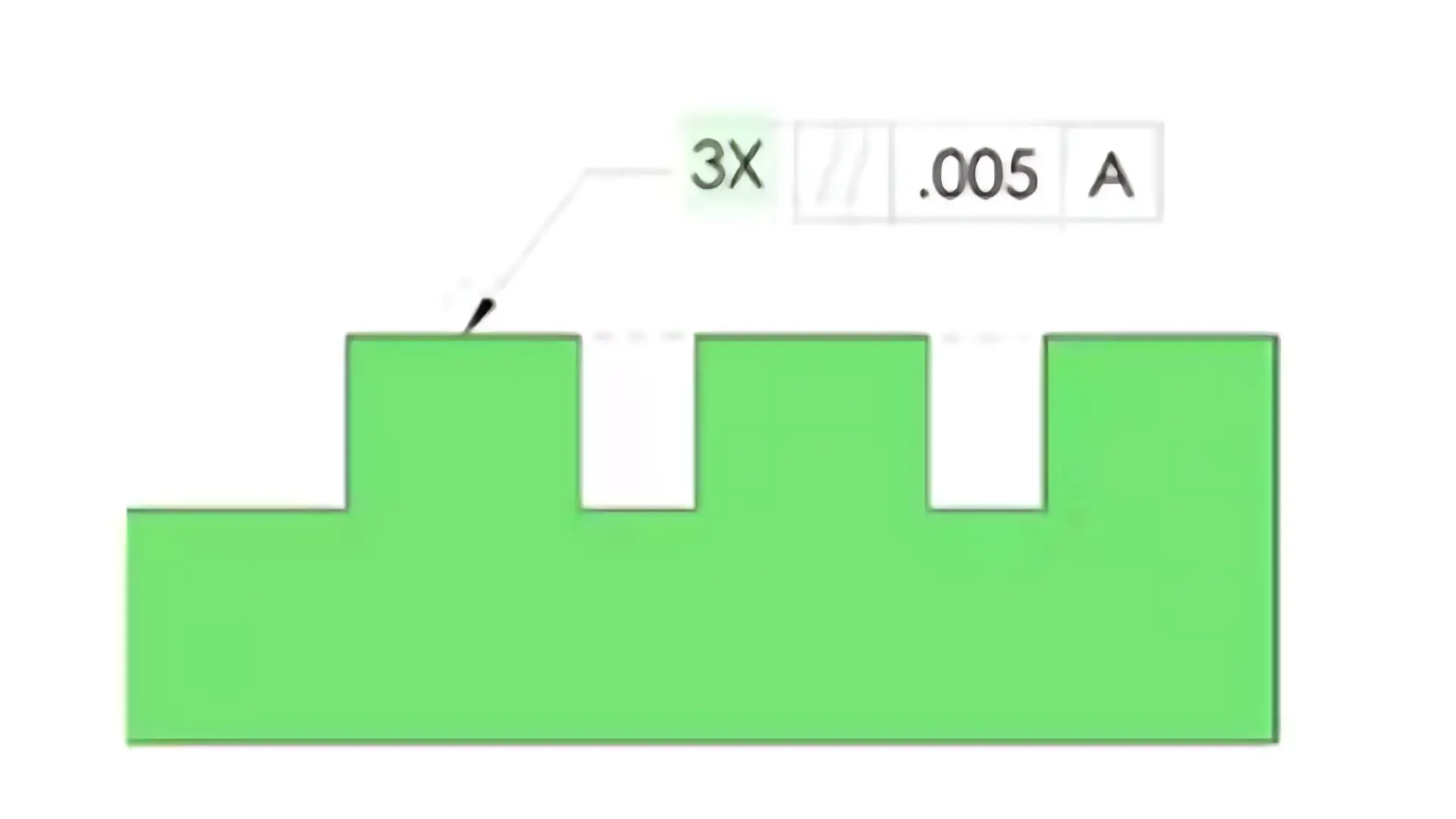
Take the above Figure for example, which shows a part with three separate similar surfaces. With a “3X” indicated in front of the feature control frame of one of the surfaces, this means that all the three surfaces are controlled by GD&T parallelism with tolerance of .005 and all of them are located by referring to datum A.

    3. An Example of Multiple Identical Features Explained

    This part would take a drawing of multiple identical features as example to for explanation.How to Use Multiple Identical Features

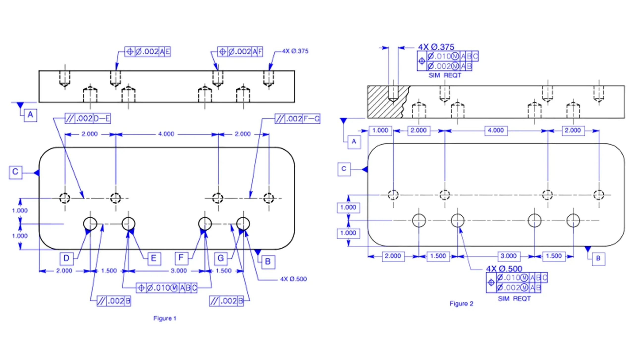
    As shown above, this part has two patterns of holes that are defined as multiple identical features.

    Figure 1 shows the drawing with several problems while Figure 2 is the exactly correct one.

    Figure 1 shows the information complexly and redundantly. Firstly, since these holes are multiple identical features, it is required to use only one basic hole to locate dimensions and also extension lines to indicate dimensions.

    Secondly, the feature control frame of the hole’s position tolerances should be indicated below the size dimension of the features.

    Thirdly, a tolerance would never be applied to imaginary lines or planes. The leader lines should be located correctly to the controlled features.

    Finally, multiple identical features should have a uniformly system of datums. It is enough to take datums A, B, and C as references.

    Figure 2 shows the information clearly and correctly, which is better for CNC machining.

    4. What are Functions of Multiple Identical Features?

    In GD&T, the main functions of multiple identical features are as follows.

    • EnhanceClarity and Conciseness of Drawings

    By indicating “#X”, like”6X” before the dimension of a single feature as represent, redundant individual annotations for each identical feature can be avoided.

    This prevents cluttering the drawing with repetitive information, making the design intent more intuitive and accessible for engineering professionals to understand quickly.

    • ImproveManufacturing Accuracy

    Clear and precise annotations can accurately convey design requirements, ensuring that each identical feature is manufactured under a uniform standard.

    This can also help to reduce misunderstandings caused by ambiguous indications, thus effectively minimizing processing errors, and ensuring product quality and interchangeability among various components of the product.

    • Support Cost Control and Efficiency Improvement

    By reducing the workload of indication and the probability of manufacturing errors, the product process from design to finished product can be effectively shortened.

    It also minimizes waste of resources( such as raw materials and labor )caused by faulty production, thereby achieving effective cost control.

    5. Multiple Identical Features VS Continuous Features

    GD&T multiple identical features and continuous features are two kinds of different symbols. They are similar to some extent, but have different key functions.

    GD&T multiple identical features are actually separate and independent features that have the same geometry and tolerance.

    In other word, though the dimensional and geometric tolerances are indicated only once pointing to one of the features, they are controlled and measured separately and independently to each other.

    The key function of the multiplier symbol is to reduce repeat indications and convey design intent more simply and clearly.

    However, GD&T continuous features refer to multiple disjointed features. They may not be totally similar, but are usually one kind of geometry and located at the same plane or curved surface.

    The key function of the continuous features symbol is to clarify that these multiple disjointed features are considered as one whole feature. It means that the tolerance zone is uniformly single.

    6. Multiple Identical Features VS Pattern Features

    Multiple identical features and pattern features are much similar to some extent. Both of them refer to multiple similar features and would use “#X” to indicate the number of these features.

    The main difference is that multiple identical features are independent to each other, while pattern features function as a whole.

    The individual accuracy of each feature with respect to datums is the key of multiple identical features.

    However, for pattern features, not only the individual accuracy referring to datums should be controlled, but also their relative positions with respect to each other should be tightly controlled.

    For multiple identical features, they are usually connected with different parts without tight assembly relationship. But patter features usually appear on assemblies that should mate with each other accurately.

    continuous features symbol

    7. Conclusion

    Multiple identical features are critical and effective in GD&T. This article has provided comprehensive knowledge of multiple identical features. If you still have some confusion, contact with us directly.

    Lucas

    Lucas is a technical writer at ECOREPRAP. He has eight years of CNC programming and operating experience, including five-axis programming. He also spent three years in CNC engineering, quoting, design, and project management. Lucas holds an associate degree in mold design and has self-taught knowledge in materials science. He’s a lifelong learner who loves sharing his expertise.

    Learn More about Lucas.

    Let's get your projects started, together!

    Get custom parts machined in high quality, delivery on time.