UAV aluminum CNC machining requires system-level precision to meet aerospace performance standards.
As UAV designs evolve toward lighter structures, tighter tolerances, and scalable production, common machining failures emerge—most notably tight tolerance deviation, thin-wall deformation, batch inconsistency, incorrect aluminum alloy selection, and insufficient engineering support.
Tight tolerance failure typically occurs during batch production due to multi-setup machining, thermal variation, and lack of in-process measurement, even when prototypes pass inspection.
Lightweight aluminum parts deform when residual stress, improper clamping, and aggressive cutting parameters are not controlled.
Inconsistent batch quality results from operator-dependent processes, non-standardized parameters, and absence of SPC monitoring.
Material misselection—such as using 6061 instead of 7075 in load-bearing UAV structures—can increase component weight by 10–18%, reducing flight efficiency.
Industry-proven solutions integrate aerospace-grade CNC equipment, locked machining parameters, stress-controlled toolpaths, material traceability, and early DFM engineering involvement.
Together, these practices enable stable, high-precision aluminum UAV part production from prototype to mass scale, demonstrating High Precision CNC Machining Solutions for UAV Aluminum Parts.
UAV Aluminum Parts Fail to Meet Tight Tolerance Requirements
UAV aluminum parts fail to meet tight tolerance requirements mainly due to unstable CNC processes during batch production, not because of insufficient machine accuracy.
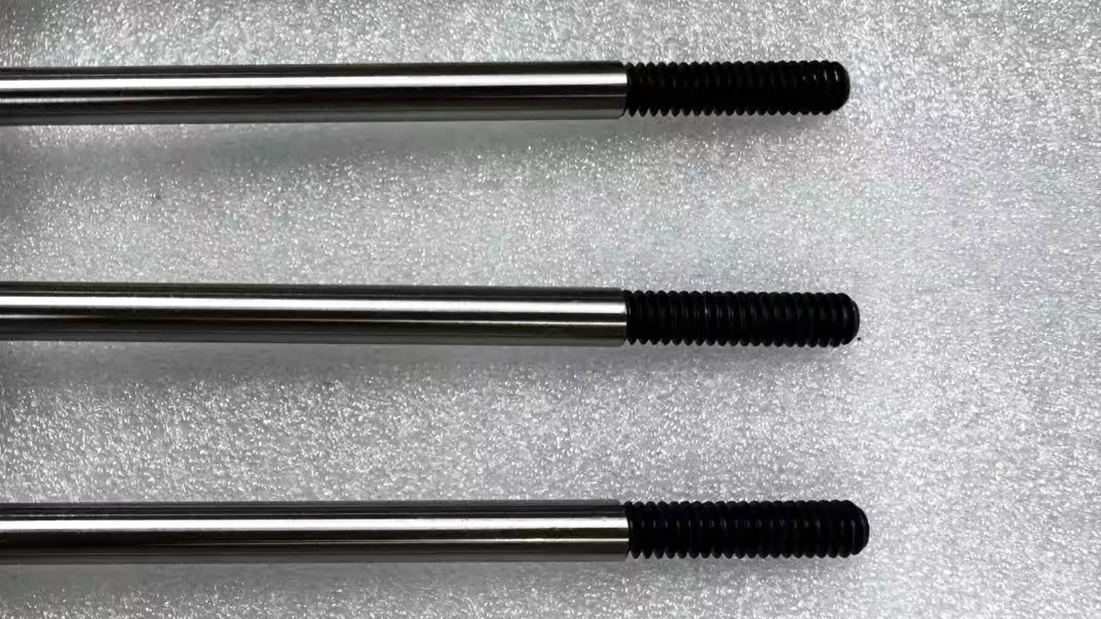
Tight tolerance CNC machining for UAV aluminum parts refers to controlling critical dimensions within ±0.01 mm to ensure flight stability and precise assembly.
In real production, dimensional deviation often appears when multi-setup machining, thermal variation, or lack of in-process measurement is involved.
Engineering practice shows that system-level controls—such as single-setup 5-axis machining, real-time probing, and CMM verification—can achieve repeatability within ±0.005 mm and significantly reduce assembly failure risk.
Manufacturing Challenges in High Precision UAV Components
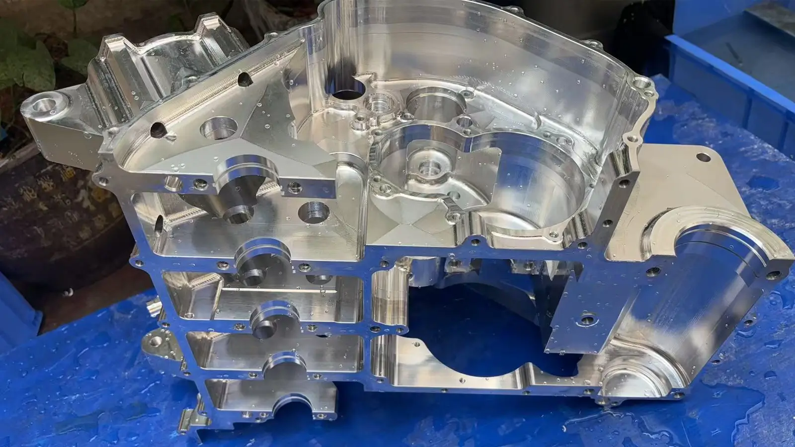
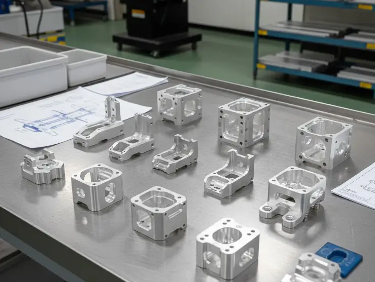
In modern UAV manufacturing, aluminum components such as UAV frames, motor mounts, and electronic housings require extremely tight tolerances, typically at ±0.01 mm or stricter. These requirements directly affect flight stability, assembly accuracy, and long-term reliability.
Many CNC machining uva suppliers claim high precision capability but fail to maintain consistent tolerance control during batch production. While prototypes may meet specifications, dimensional deviation often appears in mass production, leading to assembly issues and delayed UAV projects.
Why Tight Tolerance CNC Machining Matters for UAV Aluminum Parts?
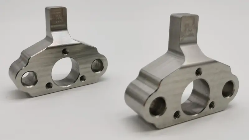
- Flight Stability and Control: Minor dimensional errors in motor mounts or structural joints can cause imbalance during high-speed rotor operation, reducing UAV flight stability and control accuracy.
- Component Lifespan and Reliability: Poor tolerance control leads to vibration and uneven load distribution, accelerating wear on motors and bearings.
- Batch Assembly Consistency: Aerospace-grade CNC machining focuses on repeatability, ensuring consistent aluminum parts for reliable UAV assembly and performance.
High Precision CNC Machining Solution for UAV Aluminum Components
Our CNC machining process is optimized for tight tolerance UAV aluminum parts used in aerospace and drone applications.
- Advanced CNC Machining Equipment: 5-axis CNC machining centers enable complex UAV aluminum parts to be completed in a single setup, reducing cumulative errors.
- In-Process Measurement: Automated probing systems monitor critical dimensions during machining and apply real-time compensation.
- Dimensional Inspection: All parts are verified using CMM inspection to ensure compliance with engineering drawings.
- Proven Precision Capability: Repeatability within ±0.005 mm is consistently achieved for Aluminum 7075-T6 UAV components.
- Inspection Documentation: First article inspection reports and dimensional records support stable batch production.
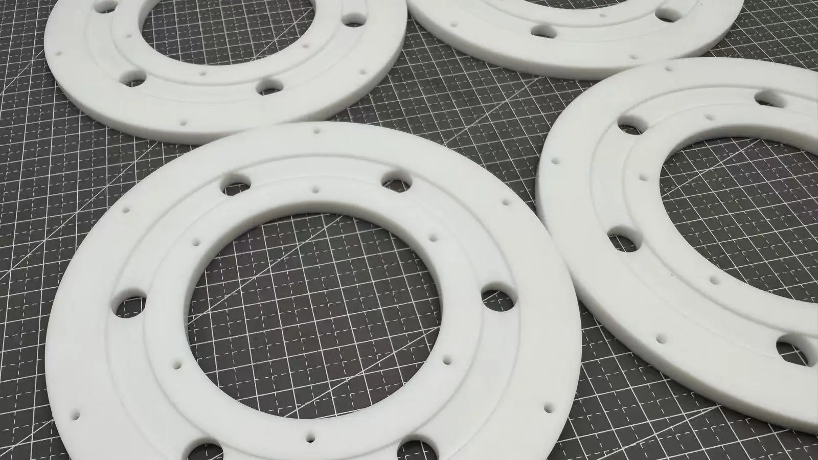
Scenario 2 — Lightweight UAV Aluminum Parts Deform During CNC Machining
Thin-wall UAV aluminum parts deform during CNC machining due to residual stress release, insufficient structural support, and excessive cutting forces.
In high-strength materials such as 7075, this issue is even more critical. You can read more in Preventing Deformation in 7075 Aluminum UAV Frames.
Lightweight UAV components with 0.8–1.2 mm wall thickness are highly sensitive to stress redistribution during material removal.
Without staged roughing, optimized toolpaths, or proper fixturing, deformation occurs after unclamping. Industry data indicates that stress-controlled machining strategies and full-surface support fixtures can reduce deformation-related scrap rates by over 30%.
Core Problem Context
Lightweight UAV aluminum components are commonly designed with thin-wall structures ranging from 0.8 to 1.2 mm to achieve weight reduction.
However, improper CNC machining strategies frequently lead to part deformation, increased scrap rates, and unexpected delivery delays, especially during batch production.
Common Deformation Risks in CNC Machining UAV Aluminum Parts
- Residual Stress in Aluminum Alloys
Internal stress retained from raw material production or previous processing stages redistributes as material is removed during cutting. This uncontrolled stress release is one of the primary root causes of deformation in thin-wall UAV aluminum parts. - Improper Clamping of Thin-Wall UAV Housings
Thin-wall components with limited rigidity are highly susceptible to elastic deformation under conventional fixture clamping forces. Once the fixture is released, spring-back occurs, resulting in dimensional deviation and geometric tolerance failure. - Aggressive Cutting Parameters Used to Shorten Cycle Time
Excessive depth of cut, width of cut, or feed rate increases cutting force and heat generation. This intensifies thermal expansion and force-induced bending in thin-wall areas, significantly increasing the risk of deformation.
Deformation-Control CNC Machining Solutions for UAV Aluminum Components
- Optimized Toolpath Simulation (CAM-Based Stress Control)
Advanced CAM software is used to simulate cutting processes and optimize toolpaths. Symmetrical machining strategies and concentric layer-by-layer material removal help ensure uniform stress release and minimize deformation. - Custom Fixture Design for UAV Aluminum Structures
Specialized fixtures such as vacuum fixtures, flexible support fixtures, or low-melting-point alloy filler fixtures replace localized clamping with large-area adsorption or uniform support, effectively protecting thin-wall aluminum structures. - Multi-Stage Roughing and Stress-Relief Machining Strategy
- Multi-Stage Roughing: Stock material is gradually removed through multiple light cutting passes, allowing residual stress to be released progressively.
- Stress-Relief Machining: Natural aging or low-temperature aging processes are applied after roughing, or a semi-finishing and stress-relief cycle is introduced to actively reduce internal stress.
- Final Finishing: After sufficient stress relief, conservative cutting parameters such as small depth of cut, high spindle speed, and appropriate feed rate for the final shaping to ensure dimensional stability.
Implementation Results
Compared to standard CNC machining processes, the comprehensive application of the above solutions can reduce the scrap rate of thin-wall aluminum UAV parts by more than 30%, significantly improving the machining quality, reliability, and on-time delivery rate of lightweight aluminum UAV components.
Scenario 3 — Inconsistent Quality Across UAV CNC Machining Production Batches
Batch inconsistency in UAV CNC machining is caused by non-standardized parameters, operator dependency, and lack of statistical process control.
When UAV production scales, uncontrolled process variation becomes the primary quality risk. ISO 9001-driven workflows, locked machining parameters, and SPC monitoring on critical dimensions enable stable replication of approved samples.
Data from industrial CNC production shows that SPC-based control can improve batch consistency by more than 40%.
Core Problem Context
When Unmanned Aerial Vehicle (UAV) OEMs scale from prototyping to mass production, inconsistent quality across different CNC machining batches often emerges, even after initial samples have been approved. This variability leads to assembly difficulties, performance inconsistency, and long-term reliability risks, ultimately impacting product credibility and brand reputation.
Why Batch Consistency Is a Major Risk in UAV CNC Machining
- Dependence on Manual Processes
Heavy reliance on operator experience for fixturing, tool setting, and process changeovers introduces human-driven variation. Differences between operators, shifts, or working conditions are amplified during batch production, directly affecting part-to-part uniformity. - Lack of Standardized Machining Parameters
During prototyping, temporary or unoptimized cutting parameters are often used to accelerate validation. If these parameters are not formally standardized before mass production, variations in spindle speed, feed rate, and cutting depth across batches or machines will result in inconsistent dimensions, surface finish, and mechanical performance. - Insufficient Quality System Documentation
Without comprehensive documentation covering raw material inspection, in-process control, final inspection, and shipment traceability, quality issues cannot be systematically prevented or traced to their root causes, leading to repeated batch-level defects.
Our Batch-Stable CNC Machining Solution for UAV Aluminum Parts
- ISO 9001:2015 Certified CNC Machining System
Our CNC machining operations strictly follow ISO 9001:2015 certified quality management processes. Every step—from order review and process planning to production execution and inspection—is procedure-driven and fully documented, forming a reliable foundation for UAV CNC machining solutions. - Locked Machining Parameters for UAV Aluminum Components
Based on material databases and extensive process validation, optimized cutting parameter packages are established for specific aluminum alloys such as 6061-T6 and 7075-T651, as well as different structural features including thin walls and deep cavities. After first-article approval, these parameters are solidified into CNC programs and work instructions to ensure identical execution across all machines, ensuring batch stability for precision CNC machining of aluminum UAV parts. - SPC-Based Process Monitoring for Critical Dimensions
For dimensions and tolerances critical to UAV assembly and function, Statistical Process Control (SPC) is applied. Real-time control charts such as Xbar-R charts are used to monitor trends during production, allowing corrective action to be taken before non-conforming parts are produced and keeping CNC machining for drone manufacturing consistently under control.
Scalable Production Capacity
Through these standardized and data-driven systems, prototyping success can be reliably replicated in mass production. Our annual capacity exceeds 50,000+ aluminum CNC machined UAV parts, enabling stable large-volume delivery while maintaining high consistency across all production batches.
Scenario 4 — Incorrect Aluminum Material Selection for UAV Applications
Incorrect aluminum material selection reduces UAV performance even when machining accuracy is acceptable.
7075-T6 aluminum provides superior strength-to-weight ratio for load-bearing UAV structures, while 6061-T6 offers better corrosion resistance for housings.
Engineering comparisons show that replacing 7075 with 6061 in structural parts can increase component weight by 10–18%, directly impacting flight endurance and efficiency.
Core Problem Context
Selecting an unsuitable aluminum alloy for UAV components can directly compromise overall performance. Improper material choices often result in poor trade-offs between strength, weight, corrosion resistance, and machinability. In real-world UAV projects, this leads to reduced flight endurance, reliability risks, and avoidable increases in manufacturing cost.
At Ecoreprap, we frequently see UAV OEMs encounter late-stage redesigns or unexpected performance issues caused not by machining accuracy, but by incorrect aluminum material selection at the very beginning of the project.
7075 vs 6061 Aluminum for UAV CNC Machining — Practical Engineering Insights
- 7075-T6: Higher Strength for Load-Bearing UAV Structures
Properties: 7075-T6 is an aerospace-grade, high-strength aluminum alloy with tensile strength approaching that of certain steels. It delivers an exceptional strength-to-weight ratio, making it a preferred material in demanding UAV applications.
Application: Commonly used for critical load-bearing and dynamic UAV components such as arm booms, landing gear, main frames, and motor mounts, allowing aggressive lightweight design while maintaining structural safety. - 6061-T6: Corrosion Resistance for UAV Electronic Housings
Properties: 6061-T6 offers balanced mechanical performance, excellent corrosion resistance (especially after anodizing), and superior ductility compared to 7075.
Application: Well suited for UAV electronic housings, bays, non-load-bearing covers, and components exposed to outdoor or humid environments requiring long-term dimensional stability. - The Cost of Incorrect Material Selection
Using 6061 aluminum in load-bearing areas instead of 7075 often requires thicker walls or added reinforcements to achieve equivalent strength, resulting in a 10–18% weight increase for that component. Conversely, using 7075 where corrosion resistance is critical can increase surface treatment costs and environmental adaptation risks.
Material-Driven CNC Machining Solutions for UAV Aluminum Parts
- Material Traceability with Mill Test Certificates (MTC)
Every batch of aerospace-grade aluminum used by Ecoreprap is supplied with complete Mill Test Certificates. Chemical composition and mechanical properties are verified before machining to eliminate risks associated with substandard material and ensure consistent aerospace-grade CNC machining quality. - Application-Based Alloy Recommendations by CNC Engineers
Ecoreprap’s CNC engineers provide material selection guidance based on part function, load conditions, operating environment, and post-processing requirements. This early-stage engineering input ensures that materials such as 7075 aluminum UAV parts are applied where they deliver the highest value. - Optimized Cutting Parameter Libraries for Each Aluminum Grade
Different aluminum alloys exhibit distinct machining behavior. Harder 7075 requires precise tool geometry and controlled cutting parameters, while 6061 demands attention to chip evacuation and built-up edge prevention. Ecoreprap maintains validated cutting parameter libraries for each alloy and temper, ensuring stable surface quality, machining efficiency, and tool life in UAV aluminum CNC machining.
Scenario 5 — UAV Projects Delayed Due to Poor Supplier Engineering Support
UAV project delays often result from CNC suppliers lacking proactive engineering and DFM support.
Suppliers limited to drawing execution fail to identify manufacturability risks early. Engineering-driven CNC partners providing DFM analysis and early process feedback can reduce total manufacturing cost by 15–25% and significantly shorten UAV development cycles.
Core Problem Context
Many traditional CNC machining suppliers act merely as “blueprint executors,” focusing only on machining to the provided drawings without a deep understanding of the final function, assembly relationships, or application scenarios of UAV components. This passive collaboration model fails to provide forward-looking input at critical design and manufacturing stages. Consequently, design flaws often only emerge late in production, leading to project iterations, cost overruns, and schedule delays.
Why Engineering Support Matters in UAV CNC Machining Projects?
- UAV Components Continuously Evolve During Testing Phases
UAV development is a process of rapid iteration. Design changes are common after prototypes undergo functional, flight, and environmental testing. A partner with engineering capability understands this iterative logic, enabling quick responses to changes and even anticipating modification directions, saving clients valuable time. - Design-for-Manufacturability (DFM) Can Reduce Total Cost by 15–25%
Experienced engineers can identify and optimize designs that are unfavorable for machining, increase costs, or impact performance during the drawing stage. For example, by advising on reasonable tolerances, optimizing fillets, or avoiding excessively deep cavities, they can significantly improve machining efficiency and yield rates while ensuring functionality, leading to substantial cost savings. - Early CNC Machining Feedback Significantly Shortens UAV Development Cycles
Introducing manufacturing expertise at the conceptual design stage prevents designs with manufacturing risks from proceeding to prototyping. Early feedback on process feasibility, material selection, and expected surface finish results helps get the design right the first time, accelerating the journey from blueprint to qualified product.
Engineering-Driven CNC Machining Solutions: The Ecoreprap Example
- Pre-Production DFM & Tolerance Optimization Analysis
Ecoreprap provides professional DFM reports before order confirmation. Its engineering team conducts a detailed analysis of 3D models and drawings, offering written optimization suggestions from perspectives of machining accessibility, assembly interference, and cost control, ensuring designs achieve optimal manufacturability while meeting all functional requirements. - Rapid Prototyping Support (7–10 Day Delivery)
To meet the rapid validation needs of UAV projects, Ecoreprap’s flexible production lines can deliver rapid prototypes within 7 to 10 calendar days. This service encompasses machining and basic surface treatment, aiming to help clients obtain physical parts in the shortest possible time for design verification or assembly testing. - Long-Term Engineering Support for UAV OEM and Tier-1 Suppliers
Ecoreprap is committed to becoming an extension of its clients’ manufacturing departments, providing full lifecycle support from prototyping to mass production. This cooperation model, centered on deep engineering collaboration—including continuous process optimization and production capacity planning—forms the foundation for ensuring that CNC machining solutions for UAVs possess long-term stability.
Conclusion
Reliable UAV aluminum CNC machining is achieved through controlled manufacturing systems rather than isolated machining capability.
High-performing suppliers consistently integrate material traceability, standardized machining parameters, in-process measurement, deformation-control strategies, and early design-for-manufacturability input into their production workflows.
When these engineering practices are applied cohesively, UAV aluminum parts can maintain tight tolerances, structural stability, and batch consistency from prototyping through mass production.
For UAV programs transitioning toward scale, selecting a CNC machining partner with proven system-level engineering control is a decisive factor in achieving long-term product reliability and predictable delivery.