GD&T projected tolerance zone can be indicated on an engineering drawing through two common methods. The main difference between the two types lies on their indications of tolerance value.
The projected tolerance zone symbol is required to be placed within the feature control frame of the specific feature according to both the two types.
The projected tolerance zone symbol is indicated by the capital letter “P” within a circle(P) in Geometric Dimensioning and Tolerancing.
The symbol should be indicated after the geometric tolerance value and any material modifiers if applicable.
However, the value of projected tolerance zone is indicated by different ways in the two types.
In the first type, the value is directly placed after the project tolerance zone symbol within the feature control frame.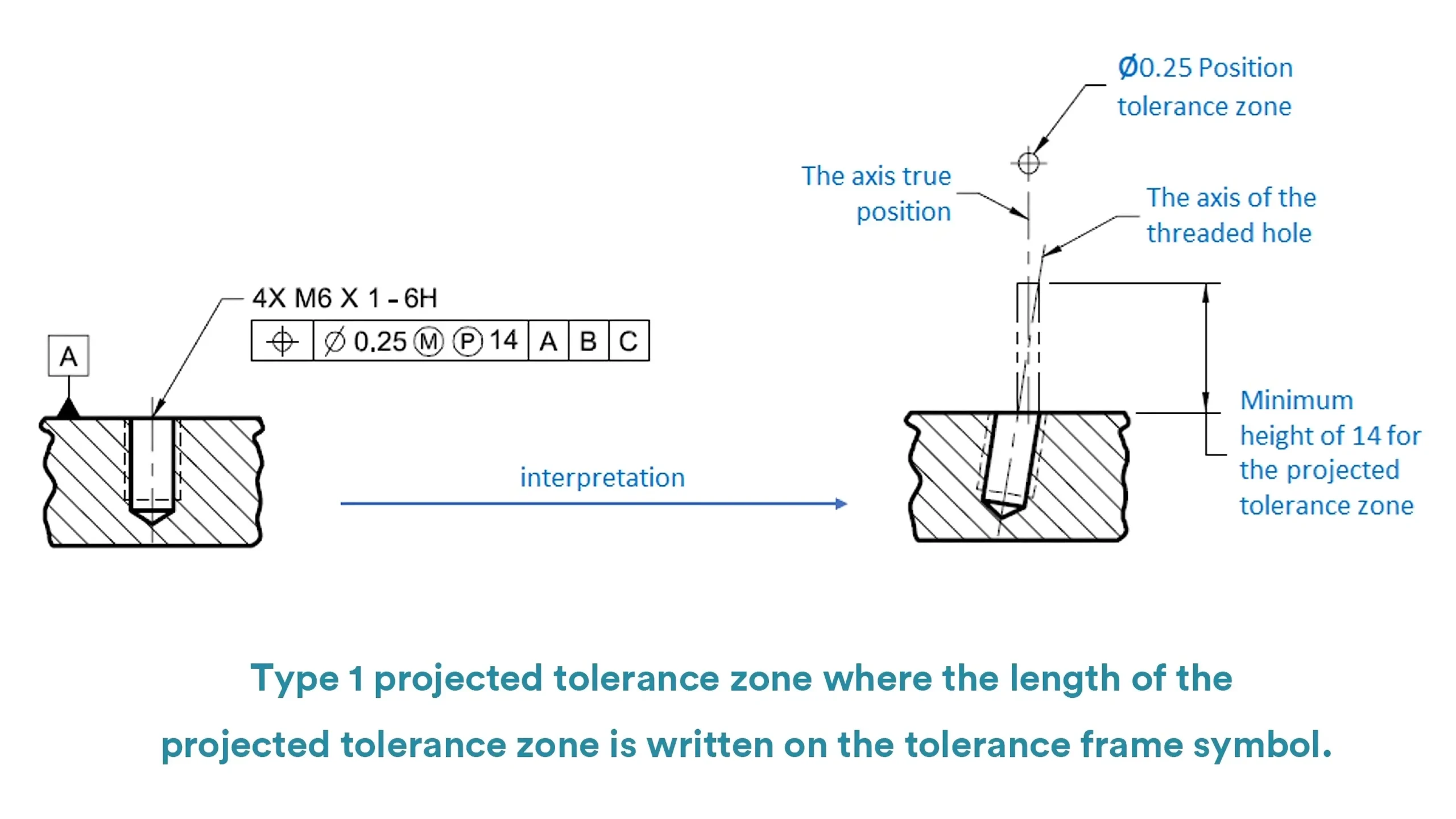
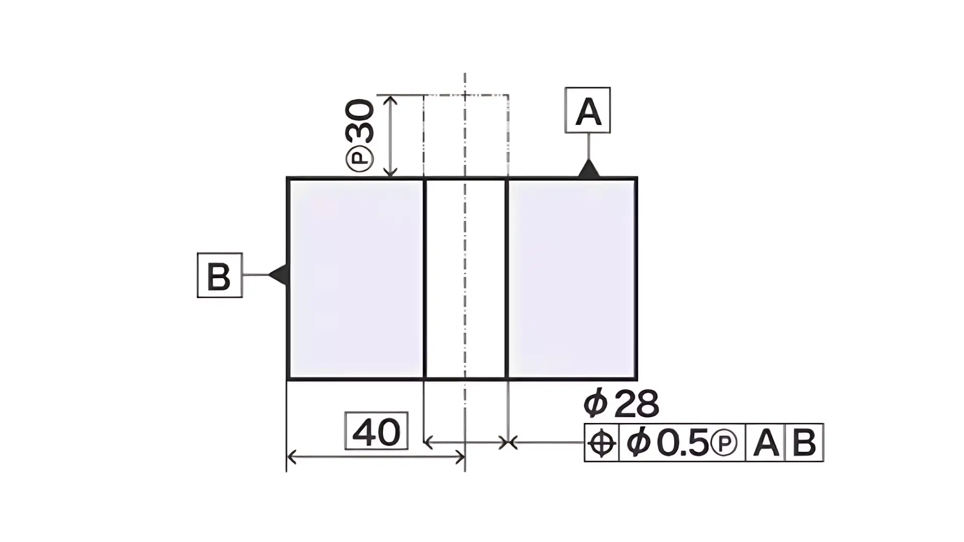
In type two, the value would not be indicated within the feature control frame, but would be indicated with a heavy chain line drawn adjacent to the extension line of the hole’s center axis.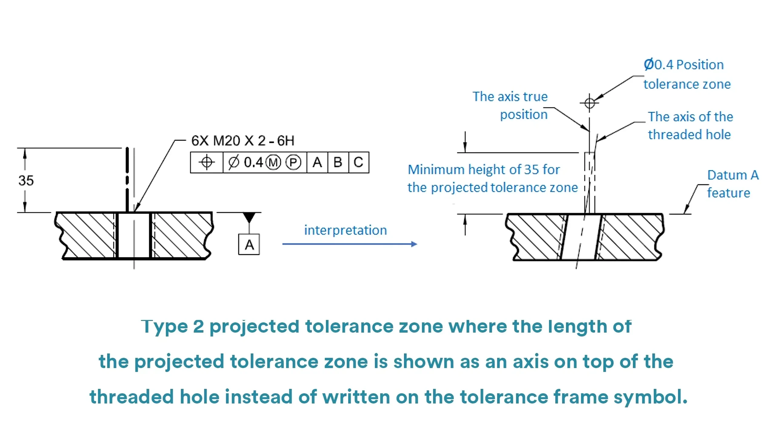
When the threaded feature is a thru hole, or the direction of the projection is unclear to some extent, the method two would be particularly chosen to indicate the projected tolerance zone.
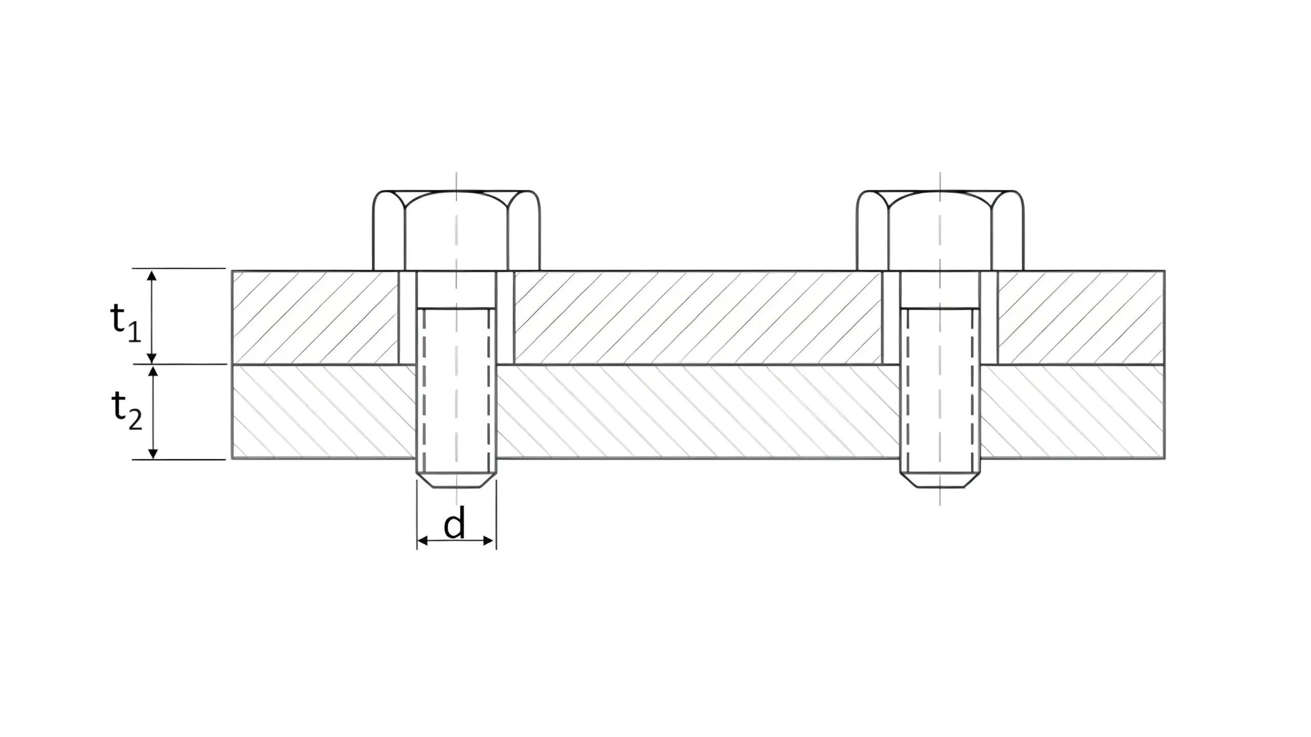
Note: Projected tolerance value in both the two methods is the minimum height of the projected tolerance zone, and is usually similar to the maximum thickness of the mating part or the maximum height of the pin.
Projected tolerance zone is a special modifier in GD&T to control the orientation and location of features for proper assembly. This part will explain the main reasons why we need projected tolerance zone through a typical example.
There is a plate and a block with a threaded hole below. They are two mating part that are required to be assembled well. Part A is a block with a threaded hole M10 and Part B is a plate with a clearance hole.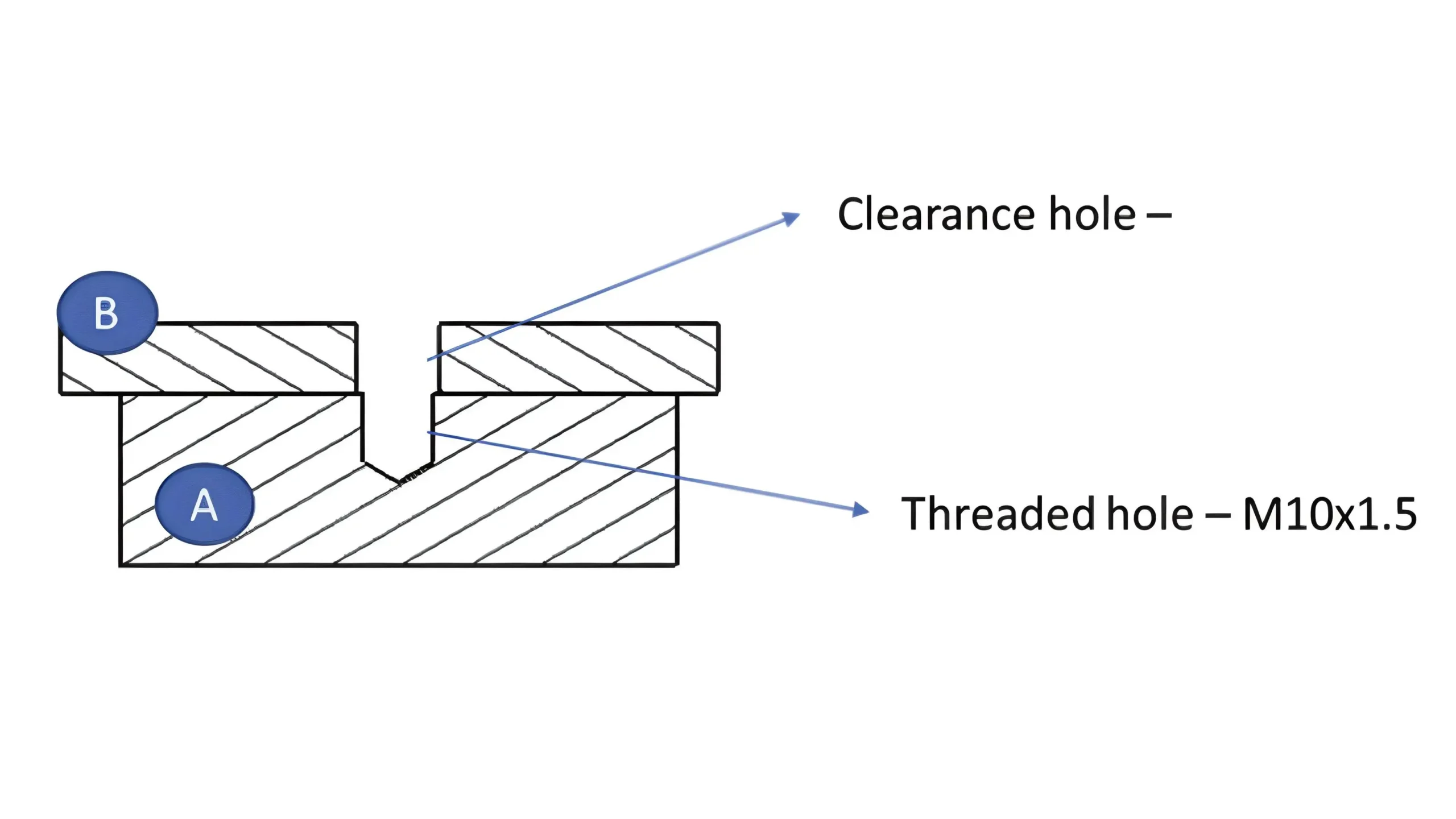
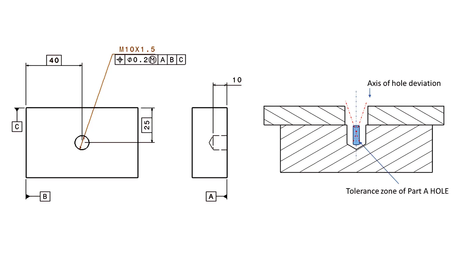
If projected tolerance zone is not used on the feature, interference on the mating part might be caused even when the feature satisfies its geometric tolerance.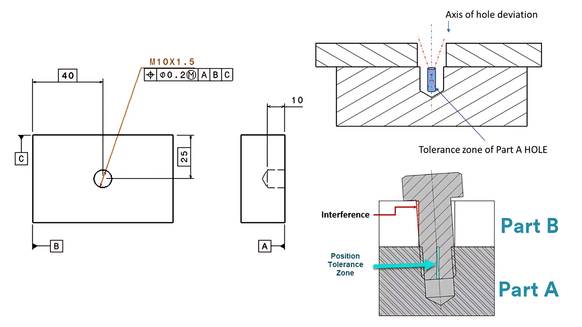
However, if projected tolerance zone is used on the threaded hole of the block, such a problem can be work out well.
Projected tolerance zone can extend the geometric tolerance zone beyond the surface of the feature to the specific height. Such a zone is virtual but can ensure proper assembly even at the worse geometric condition.
From this example, we can find that there are critical functions of GD&T projected tolerance zone.
Firstly, by controlling the feature’s position at the mating part, projected tolerance zone makes huge effects on preventing interference or misalignment during assembly.
Secondly, since proper assembly between the mating parts is assured due to projected tolerance zone, the functions of these features can be guaranteed well even if the hole is slightly tilted within its tolerance.
Thirdly, GD&T projected tolerance zone allows for more efficient manufacturing processed by providing clear guidelines for feature location and orientation.
However, you might confuse that why we can not prevent interference by tightening the geometric tolerance, which has the same effect of projected tolerance zone.
But projected tolerance zone can help to prevent interference and meanwhile allow larger geometric tolerance.
It is true that projected tolerance zone might tighten the geometric tolerance due to the extended zone, but it still allows the threaded hole to use its original tolerance. This means that if the threaded hole does not tilt, then the position tolerance value still allows the axis to drift left or right within the zone.
However, projected tolerance zone can not be applied to all fasteners at all conditions. There are two rules for application of projected tolerance zone.