Home » Blog » Restrained Condition Note Explained with Drawings

Restrained Condition Note Explained with Drawings

By Lucas Lo | Updated: May 22, 2025

Table of Contents

    In GD&T, the Restrained Condition Note is an indispensable element. This article focuses on the key technical approach of “Restrained Condition Note,” deeply exploring its core definition within the GD&T system, the implementation details of drawing annotation rules, its application throughout the mechanical machining process, and the challenges and solutions in typical industries such as aerospace and automotive manufacturing.

    The goal is to provide engineers with a comprehensive framework from theory to practice, aiding in resolving the inspection and assembly accuracy issues of deformable parts.

    1. What is a Restrained Condition Note?

    When a part’s deformation in the free state conflicts with its functional performance after assembly, how can its true performance be accurately evaluated through technical means?Restrained Condition Explained

    This section deeply analyzes the underlying logic of restrained condition note, compares its core differences with the free state, and clarifies its normative significance in machining by referencing international standards. This facilitates a systematic understanding of this key concept.

    1.1 Core Definition

    In the geometric dimensioning and tolerancing (GD&T) system, Restrained Condition Note refers to the requirement for dimensional and geometric tolerance inspection of parts under controlled external constraints (such as fixture clamping force, assembly pretension force) through technical documents.

    -Essential function: Override the default “Free State” of the part, and force it to be evaluated in the simulated actual assembly or working state to ensure functional conformity.

    -Standard basis: follows ASME Y14.5-2018, ISO 1101 and other international standards, and transmits technical requirements through drawing annotation (such as datum constraints, force parameters).Restrained Note

    1.2 The Core Difference from the State of Freedom

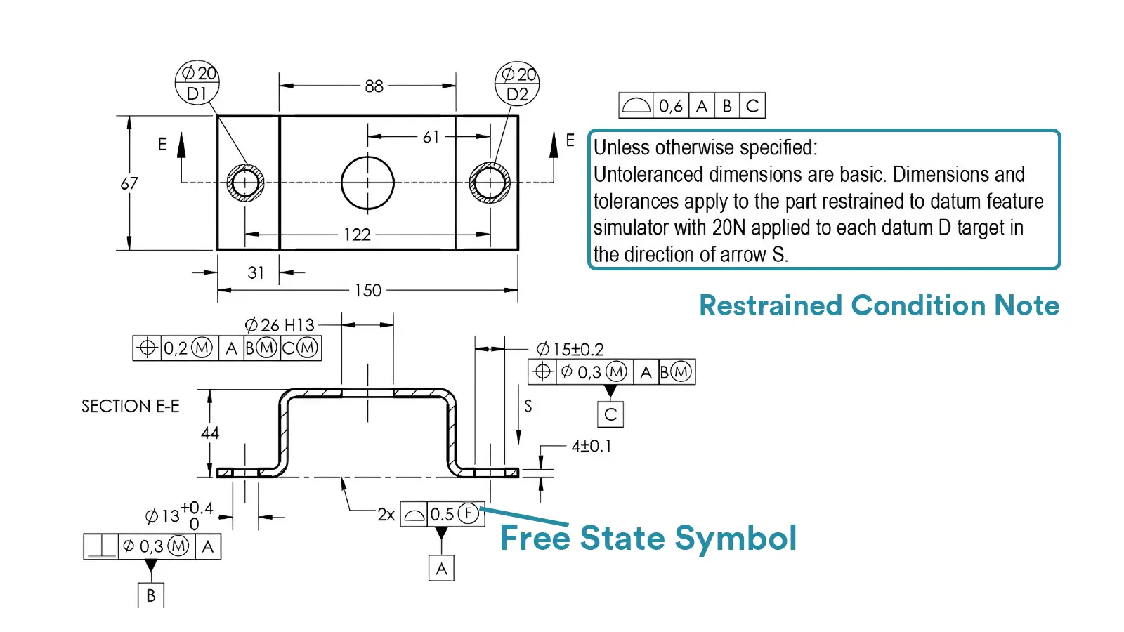
    Table 1: Key Differences Between Free State and Restrained Condition

    AspectFree StateRestrained Condition
    ConstraintOnly gravitational force; no external fixtures (clamps, fasteners, etc.)Specific constraints applied (e.g., 15N clamping force, dowel pin fixation)
    Inspection GoalGeometric accuracy in the part’s natural stateFunctional accuracy simulating assembly/operational conditions
    Typical ScenariosRigid parts, structures with no assembly deformation riskThin-walled components, rubber parts, multi-component assemblies

    2. What are the Drawing Rules and Examples for Restrained Condition Annotation?

    Drawing annotations are the “language” for conveying technical requirements, but vague constraints can lead to execution deviations in machining and inspection.

    This section breaks down the specification requirements for annotation elements such as datum constraints and force parameters.

    It showcases how to precisely convey constraints through authentic engineering drawing cases.

    Additionally, it addresses conflict-resolution strategies when free and restrained conditions are present simultaneously. This guarantees the uniqueness and operational viability of technical documents.

    2.1 Labeling Elements and Specifications

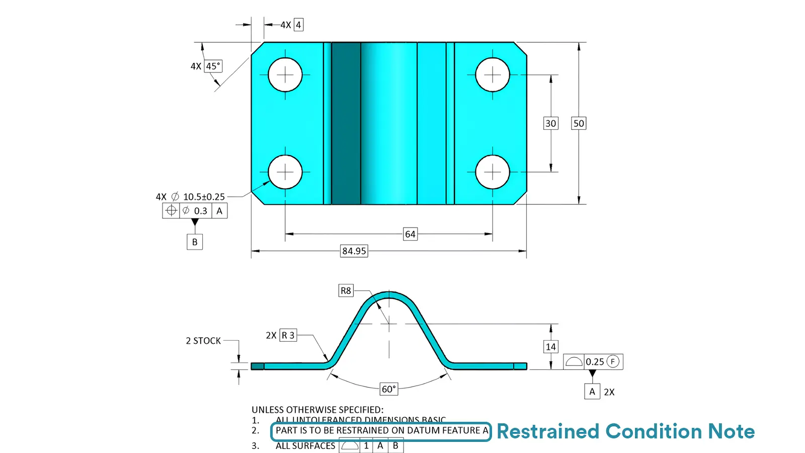
    -datum constraint description

    Clearly constrained datum features (e.g., “Restrained on Datum A”) are usually associated with the part’s positioning surface.

    Example:

    “PART TO BE RESTRAINED ON DATUM FEATURE B USING HYDRAULIC CLAMPS.”Restrained Condition Note in Drawing

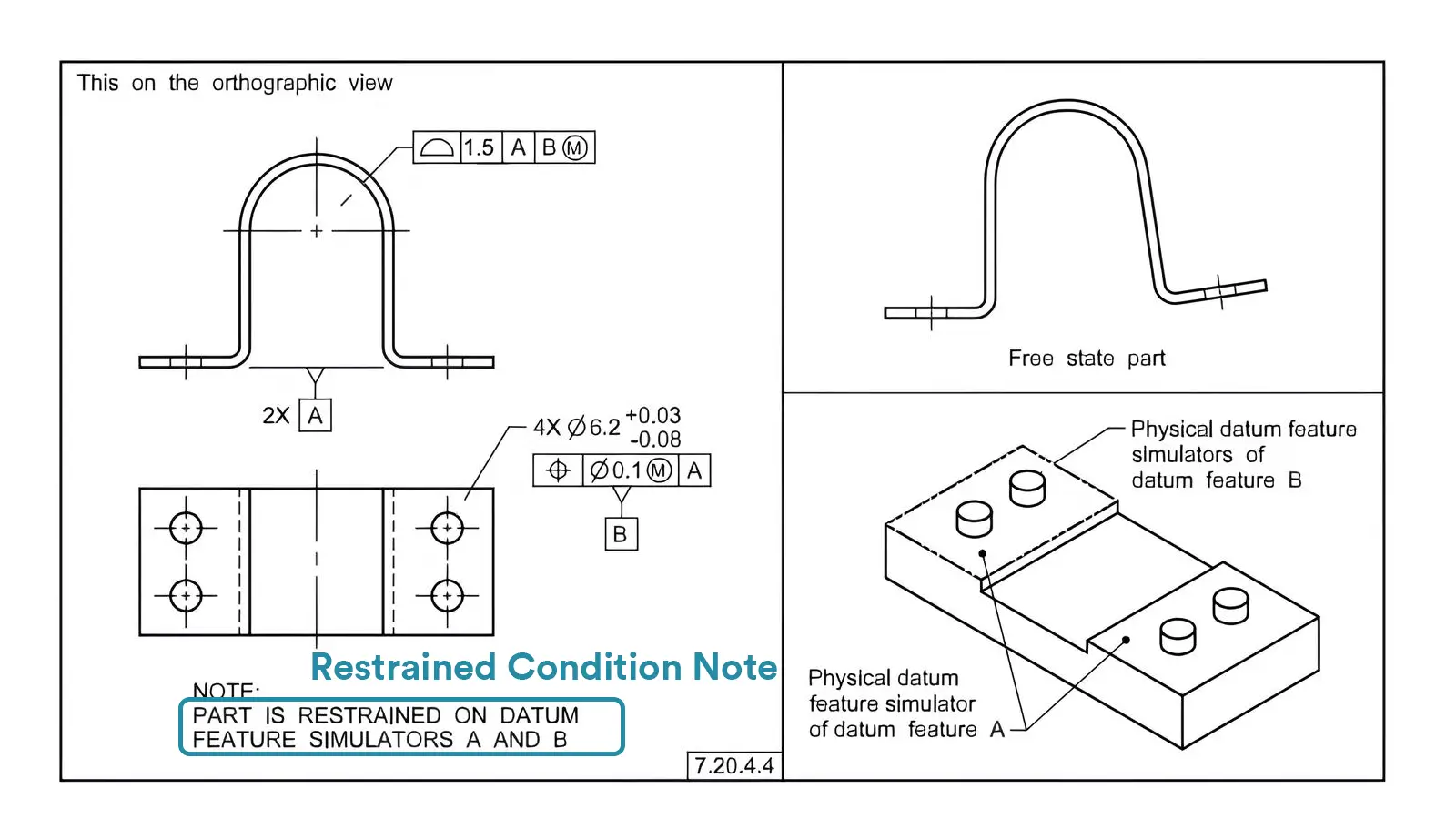
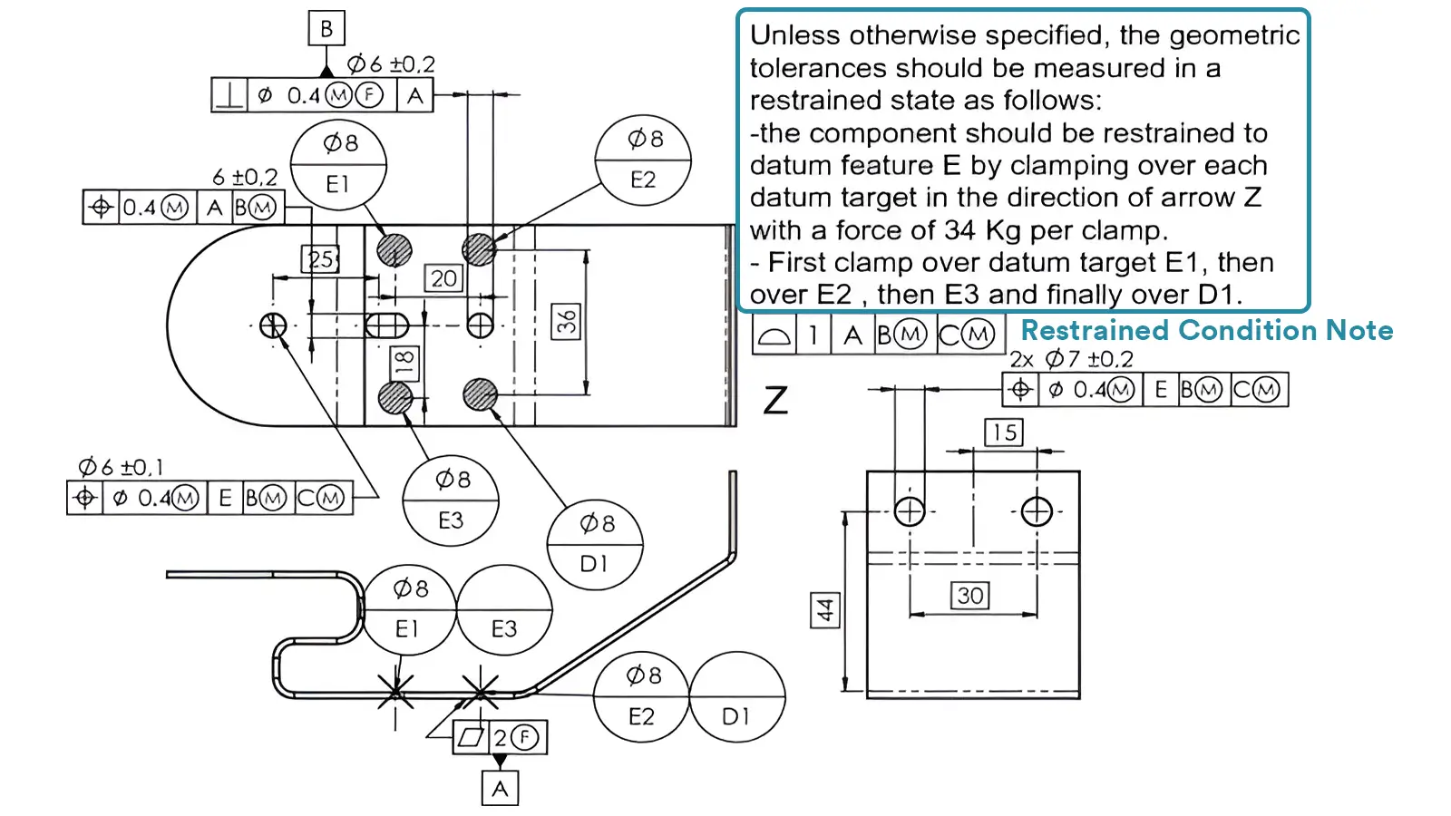
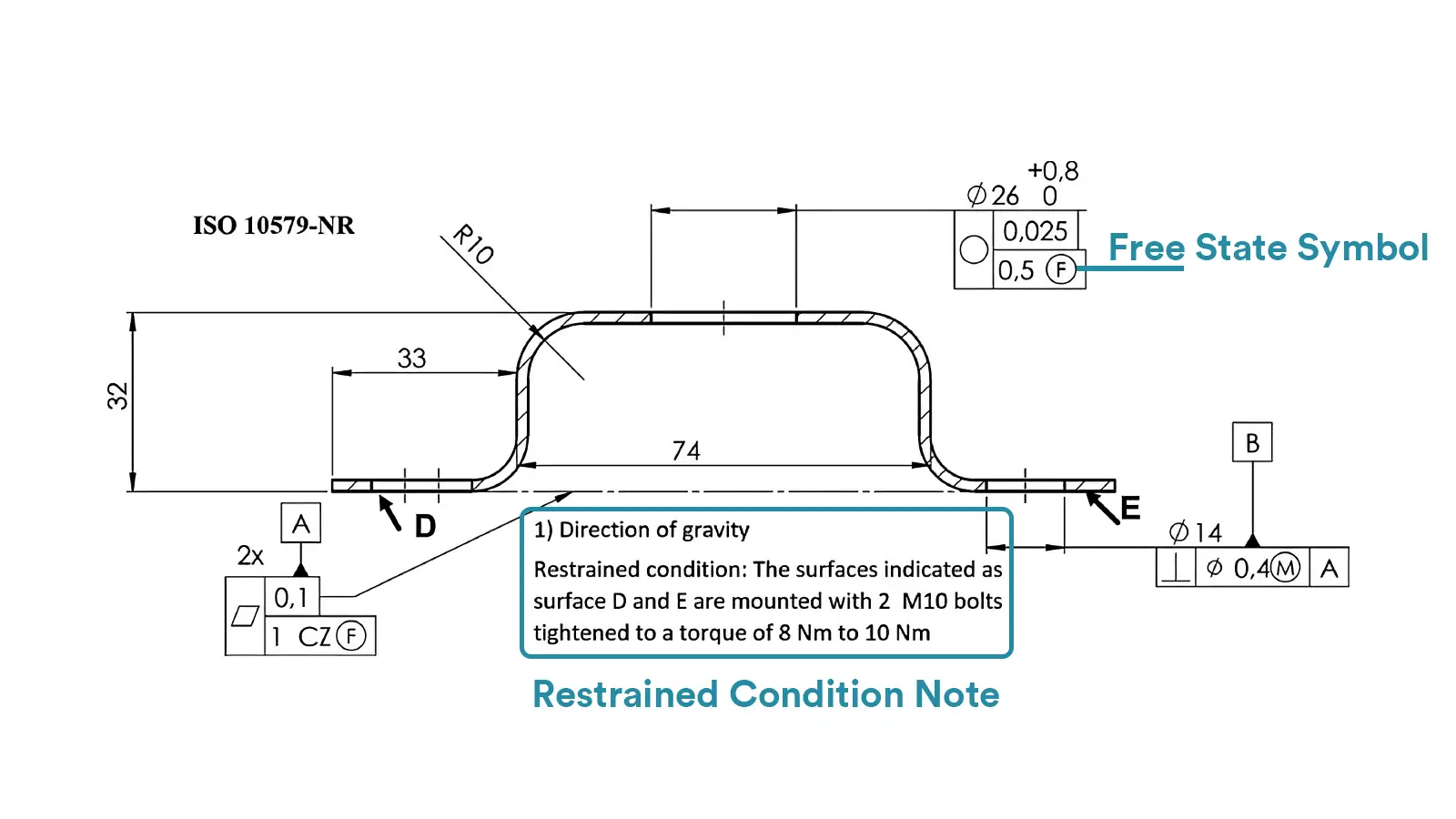
    -Force value and constraint method

    Indicate the applied physical force parameters (such as clamping force, torque) or the type of restraint tool (such as magnetic fixtures, bolts).

    Example:

    “APPLY 20-25N FORCE VERTICALLY ON SURFACE C DURING INSPECTION.”

    -Mark the position

    It is usually located under the drawing title column or tolerance box, and is used in conjunction with the GD&T symbol (such as the reference symbol Ⓐ).

    2.2 Conflict Resolution with the State of Freedom

    When some features of the parts need to be tested in a free state, they need to be marked separately in the corresponding tolerance box (Free State Symbol) (such as F), and the remaining features follow the Restrained Condition requirements by default.

    3. When is it Necessary to Apply a Restrained Condition Note in Machining?

    Although free-state inspection is adequate for rigid components, specific materials, geometrical configurations, or functional requirements necessitate the use of restrained-state notes.

    Here’s how to identify these scenarios: material properties (e.g., elastic springback in aluminum alloys), part geometry (e.g., low rigidity in thin-walled components), and functional requirements (e.g., assembly preload for seals). By integrating typical CNC machining scenarios, readers can quickly identify applicable contexts.

    3.1 Trigger Conditions of Material Characteristics

    -High elasticity / low rigidity materials:

    Aluminum alloy and titanium alloy thin-walled parts (prone to deformation due to clamping force during processing, and rebound after release).

    Rubber, nylon, and other flexible materials (size shift due to self-weight).

    -Case: When CNC milling a 1.5mm-thick aluminum alloy aviation bracket, the flatness in the free state is 0.3mm, and it is qualified after applying a uniform clamping force of 10N through the fixture.

    3.2 Parts Structure Trigger Conditions

    -Thin wall / slender structure:

    Engine blades are prone to twisting from cutting forces during milling, while slender shafts are liable to bend during turning.

    -Solution: use segmented clamping + auxiliary support, and mark “restrained at 3 equidistant points with 8N force” on the drawing.

    3.3 Functional Requirements Trigger Conditions

    Scenes where assembly accuracy is prioritized:

    Car engine cylinder head gasket (need to ensure sealing in the pre-tight state of the bolt).

    Precision instrument rail components (need to simulate the constrained state after installation to detect the straightness).

    4. How to implement the Restrained Condition in the whole Process of CNC machining?

    From process planning to inspection and acceptance, the implementation of Restrained Condition Note requires coordination across multiple stages.

    This section will focus on the CNC processing site, discuss how to realize the unification of processing and testing datums through integrated fixture design, how to reserve deformation compensation in CNC programming, and the key points of environmental control and data traceability in the testing link, and present from “design requirements” to “qualified products” a complete implementation path.

    4.1 Process Planning Stage: Fixture and Program Coordination

    -Fixture design

    Developing integrated inspection-machining fixtures ensures that constraint datums align with CNC positioning datums (such as using the same set of positioning pins).

    Example: Design a pressure plate incorporating a force sensor for thin-walled sheet metal parts, and monitor the clamping force in real time within the range of 15 ± 2 N.

    -CNC programming adjustment

    For parts that need to simulate assembly constraints, reserve the constraint deformation compensation in the roughing stage.

    Strategy: When milling in layers, the last knife is processed at a low feed rate (50mm/min) to reduce the impact of cutting stress on the restraint state.

    4.2 Testing Stage: Standardized Operation Process

    -Equipment and environment

    Use a three-coordinate measuring machine (CMM) to inspect in a restrained state, avoiding human contact that may change the position of the parts.

    Control the temperature of the detection environment (20±2℃) to reduce the interference of thermal deformation to the constrained state.

    -Data recording and tracing

    Save the constraints parameters (such as fixture number, force value record), and bind and archive with the test report.

    Case: The inspection report of a medical equipment parts states: “Constrained by Datum A using fixture #F-007, clamping force 18N, and the test results meet the requirements of ASME Y14.5.”

    5. What are the Typical Applications of the Restrained Condition Note in Various Industries?

    Industry-specific part performance requirements vary significantly. How does the restrained condition note adapt to specialized needs in aerospace, automotive manufacturing, and other fields?

    Through three real-world industry cases, this section showcases practical solutions such as vacuum adsorption for titanium alloy wing ribs, torque simulation for engine seal flanges, and phased accuracy verification for optical components, providing reusable cross-industry application references.

    5.1 Aerospace: Constraint Detection of Thin-walled Structural Parts

    Scene: Processing titanium alloy wing ribs (wall thickness 2mm, dimensional tolerance ±0.1mm).

    Challenge: In the free state, the abdominal plate is warped due to the release of cutting stress.

    Solution:

    Drawing notation: “ALL DIMENSIONS APPLY WITH PART RESTRAINED TO DATUM PLANE X VIA VACUUM CHUCK (PRESSURE: -80kPa).”

    Test results: the flatness is reduced from 0.4mm in the free state to 0.05mm in the constrained state, meeting the aerodynamic requirements.

    5.2 Automobile Manufacturing: Simulation of the Assembly State of Seals

    Scene: Engine oil sump sealing flange (material: HT250, need to withstand bolt pretension force).

    Constraint scheme:

    Use a special fixture to simulate the 12N・m torque constraint of 6 bolts.

    Testing item: Flange flatness (≤0.03mm in the constrained state) to ensure that there is no leakage after assembly.

    5.3 Precision Instruments: Stress-free Detection of Optical Components

    Scene: Laser gyroscope cavity (aluminum alloy, require roundness ≤0.005mm in the free state).

    Special treatment:

    For the characteristics of free state and constrained state that need to be evaluated at the same time, phased testing is adopted:

    First test: test the assembly-related size in the constrained state.

    Subsequent inspection: After releasing constraints, a laser interferometer measures free-state roundness by analyzing light wave interference patterns. This method detects deviations as small as 0.001mm, ensuring the cavity meets the ±0.005mm tolerance requirement.

    6. What Challenges will the Application of Restrained Condition Note face?

    In practice, restrained condition note may face challenges like over-constraint deformation and cross-team communication gaps.

    This section combines mechanical principles and project management experience to analyze over-constraint risks, introduces solutions like floating fixture design and finite element simulation, and discusses how to enhance collaboration efficiency through cross-departmental reviews and visual annotation tools (e.g., constraint schematics) to avoid execution-level issues.

    6.1 Overpositioning Problems caused by Constraint Stress

    Risk: Excessive restraint may introduce additional deformation and cover up the real assembly performance.

    Solution:

    Engineers use floating fixtures to allow minor elastic deformation, simulating real-world loading conditions.

    Optimize the fixture layout by simulating and previewing the constraint stress distribution via finite element analysis (FEA).

    6.2 Information Faults in Multi-team Collaboration

    Risk: The design, processing and testing teams have inconsistent understanding of constraints.

    Solution:

    Attach a schematic diagram of the constraint state to the drawing (mark the position of the fixture and the direction of force).

    For example, in a automotive gasket project, design and machining teams initially disagreed on clamping force parameters. A cross-departmental review involving FEA simulation and fixture prototyping resolved the discrepancy, reducing rework by 30%.

    7. How to Establish a Best Practice and Standard System for Restrained Condition Note?

    Standardization is the core of improving the stability of processing quality.

    Starting from the construction of the enterprise-level process system, this section proposes to establish a constraint status database, carry out GD&T special training, and refer to ASME, ISO and other international standards to clarify the technical bottom line.

    At the same time, fixture design and stress analysis tools are recommended to help readers transform theoretical requirements into practical processes and build a scientific quality control framework.

    7.1 Standardized Process Suggestions

    Establish an enterprise-level constraint status database:

    The database should include constraint force thresholds and fixture types for common materials (e.g., aluminum alloy, stainless steel).

    Training focus:

    Operators should be proficient in the GD&T note rules (such as reference symbols and force units).

    Inspectors need to be familiar with special measurement methods in the constrained state (such as dynamic force loading detection).

    7.2 Standards and Resources

    Basic standards:

    “ASME Y14.5-2018 Dimensioning and Tolerancing Chapter 9 (Free State and Restrained Condition).”

    “ISO 26287-2010 Geometrical product specifications (GPS) specifications on constrained detection.”

    Tool recommendation:

    “Fixture design software: AutoCAD Mechanical, SolidWorks Toolbox (including standard fixture library).”

    Stress analysis tool: “ANSYS Workbench (simulating the deformation trend in a constrained state).”

    8. Conclusion

    The Restrained Condition Note serves as a critical bridge between a part’s designed functionality and its actual machining performance, especially for deformable materials and complex geometries. Precise constraint annotations effectively address the limitations of free-state inspection.

    With the rise of smart fixtures and real-time force-control systems, Restrained Condition Note is evolving to integrate AI-driven deformation predictions. This trend will further bridge the gap between design intent and as-manufactured performance, ensuring parts meet rigorous demands in Industry 4.0 applications.

    Lucas

    Lucas is a technical writer at ECOREPRAP. He has eight years of CNC programming and operating experience, including five-axis programming. He also spent three years in CNC engineering, quoting, design, and project management. Lucas holds an associate degree in mold design and has self-taught knowledge in materials science. He’s a lifelong learner who loves sharing his expertise.

    Learn More about Lucas.

    Let's get your projects started, together!

    Get custom parts machined in high quality, delivery on time.