Home » Blog » Slope Modifying Symbol in GDT

Slope Modifying Symbol in GDT Explained

By Lucas Lo | Updated: Aug. 25, 2025

Table of Contents

    In Geometric Dimensioning and Tolerancing(GD&T), slope modifying symbol is used to define the “flat taper” of a controlled feature on an engineering drawing.

    1. What is Slope Modifying Symbol in GD&T?

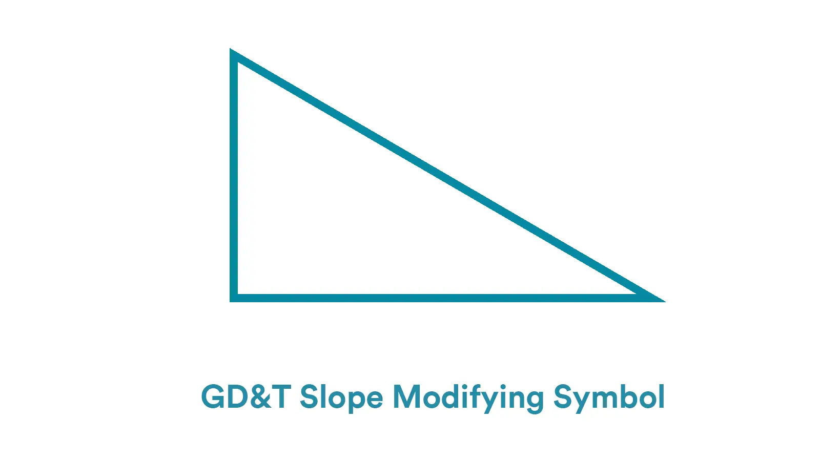
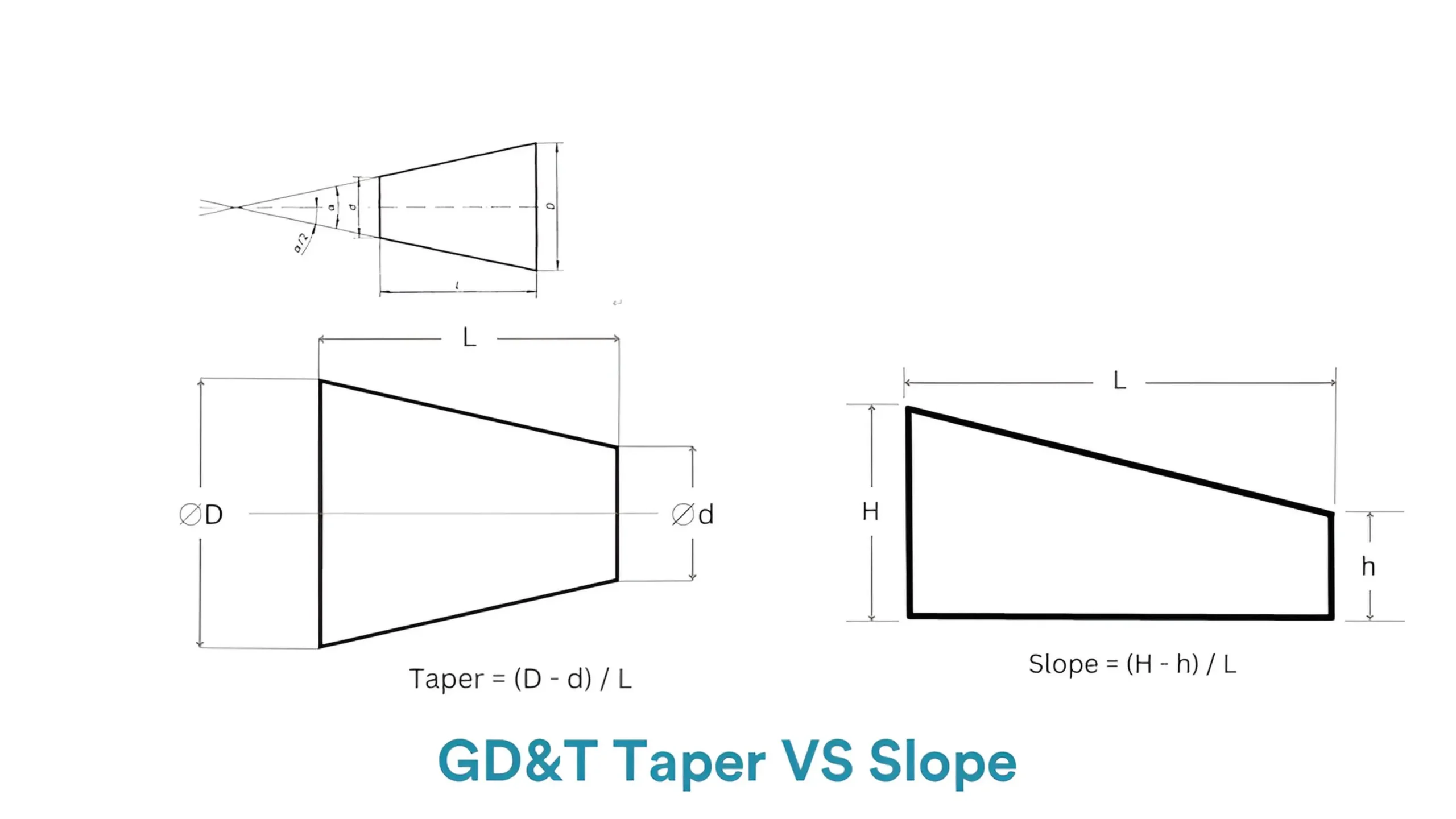
    The GD&T slope modifying symbol is used in engineering drawings to control the slope or “flat taper” of a feature. The slope is refined by the indicated value with the GD&T slope modifying symbol, referring to the ratio of the height change to length change.how to calculate slope

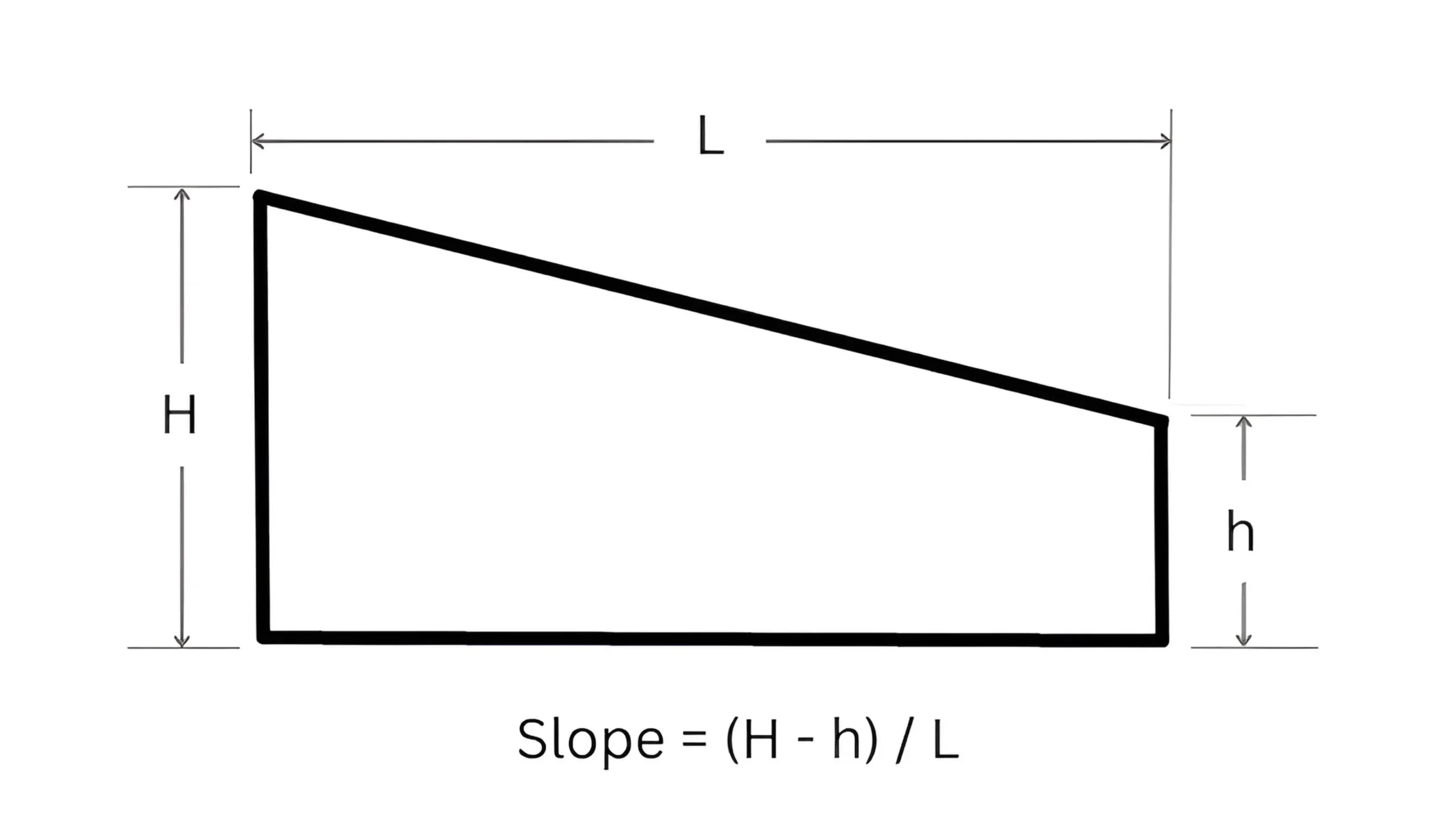
    The GD&T slope modifying symbol is represented as a right triangle on engineering drawings with a specific value on the right. The symbol is usually close to the slant of a controlled feature and is connected with a leader arrow which points to the controlled slant.

    What’s more, the inclined direction of the slope modifying symbol must be consisted with that of the actual direction of the slant.

    However, the slope modifying symbol must be indicated on an engineering drawing with the short vertical leg on the left, regardless of the actual direction of the feature shown on the drawing.

    In addition, the indicated value beside the slope modifying symbol is commonly the basic dimension of the slope. In other word, the value is the theoretically exact dimension of the controlled slope without tolerance.How to Indicate a Slope

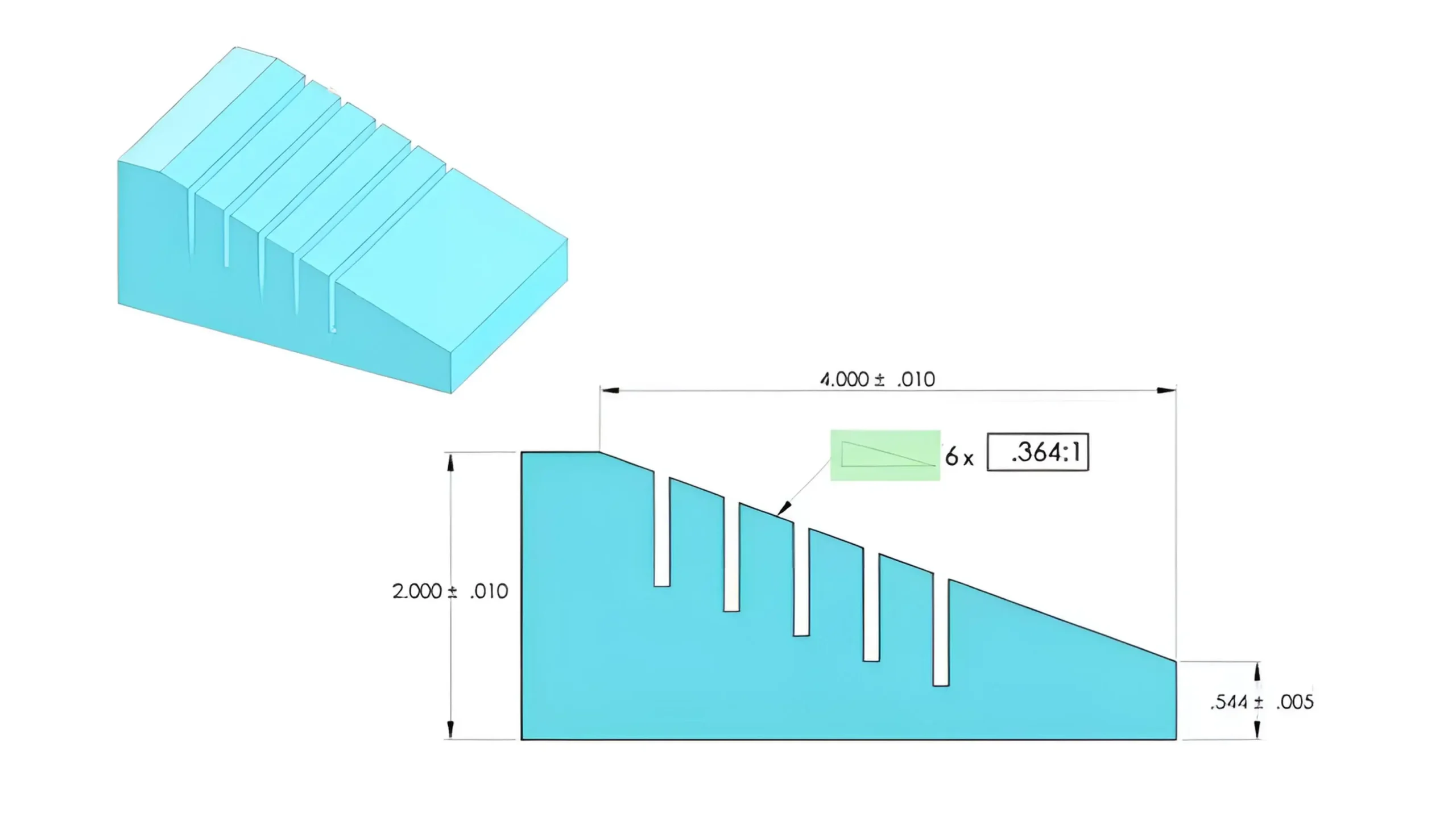
    This is due to that the height and length dimensions from which it is calculated decide the slope value together.

    GD&T Slope Modifying Symbol

    2. What are Functions of GD&T Slope Modifying Symbol?

    The key function of GD&T slope modifying symbol is to precisely control a feature’s slope, and thus to ensure the consistency among design purpose, manufacturing and inspection. The main functions of GD&T slope modifying symbol are as follows.

    • Clear Quantitative Expression of Slopes

    The GD&T slope modifying symbol directly defines the slope of an inclined feature through a ratio value, constraining the relationship between the height change and length change of the slope.

    For example, the annotation of “1:5” indicates that for every 5 units of length extended in the reference direction, the height of the inclined feature changes by 1 unit in the vertical direction.

    Compared with symbol that directly controls an angle, such as 3° or 5°, the GD&T slope modifying symbol can effectively avoid potential ambiguity on control of precision.

    Especially in long-distance inclined structures, proportional annotation can more intuitively reflect the actual dimensional relationship and reduce errors in manufacturing and measurement.

    • Constrain Direction and Position of Inclined Features

    When used in conjunction with datums, the slope modifying symbol can clearly constrain the direction of the inclined feature relative to the datum.

    For instance, if the slope symbol is annotated with datum A, the inclined slant must refer to datum plane A. It is necessary to ensure that the inclined direction of the slant strictly follows the proportional relationship and that its position relates to datum A as designed.

    This constraint ensures functions and fitting accuracy of the inclined feature with mating parts in assembly.

    • Simplify Drawing Indication and Avoid Ambiguity

    For inclined parts with complex features, the GD&T slope modifying symbol enables the clear transmission of design intent through unified indicational rules, which can avoid misunderstanding caused by viewing direction and dimensional correlations.

    3. How to Measure GD&T Slope Modifying?

    This part will explain three common measuring methods for GD&T slope modifying symbol.

    • Coordinate Measuring Machine

    This is one of the most precise and common methods for slope symbol measurement, particularly suitable for complex parts or high-precision requirements.

    Steps:

    1. Establish a coordinate system consistent with the indicated datums.
    2. Select multiple feature points from the measured inclined surface (typically evenly distributed, with the quantity determined based on precision requirements).
    3. Measure the three-dimensional coordinates (X, Y, Z) of these points and calculate the actual slope by software.
    4. Compare the actual slope with the theoretical slope indicated on the drawing.
    • Height Gauge and Right Triangle Gauge

    This is the simplest measuring means for GD&T slope modifying symbol with low cost, suitable for rapid inspection of simple planar inclined features.

    Steps:

    1. Use a right triangle gauge to calibrate the perpendicularity of the measurement benchmark relative to the datum plane.
    2. Select two points on the inclined surface with a known distance between them
    3. Use a height gauge to measure the height difference between the two points and calculate the actual slope.
    • Laser Scanning Machine

    Due to non-contact measurement, laser scanning machines can avoid damage to precision parts. Additionally, since they can comprehensively reflect the accuracy of the entire inclined surface, laser scanning machines are suitable for measuring inclined features on large parts or complex curved surfaces.

    Steps:

    1. Use a laser scanner to perform a 3D scan for the measured area and obtain point cloud data.
    2. Fit the actual inclined surface by software and calculate its slope.
    3. Compare with the theoretical value and generate a deviation report.

    4. Conical Taper Symbol VS Slope Modifying Symbol

    The main difference between the conical taper symbol and the slope modifying symbol is that the former is used on 3D conical surfaces while the latter is applied to planar surfaces.

    The GD&T conical taper symbol is applied to define the top taper of a conical surface, usually with a value referring to the basic dimension of the taper. The value refers to the ratio of the diameter change to the length change.

    The taper symbol focuses on the taper itself, commonly not relative to datums.

    The GD&T slope modifying symbol is used to define the slope of a planar surface, usually with a value referring to the slope. The value refers to the ratio of the height change to the length change.

    In addition, slope symbol is much more related to datums.

    GD&T Taper VS Slope

    5. Conclusion

    The GD&T slope modifying symbol plays an important role in controlling inclined features. This article has provided detailed information of GD&T slope modifying symbol. If you are still confused with it, contact with us directly.

    Lucas

    Lucas is a technical writer at ECOREPRAP. He has eight years of CNC programming and operating experience, including five-axis programming. He also spent three years in CNC engineering, quoting, design, and project management. Lucas holds an associate degree in mold design and has self-taught knowledge in materials science. He’s a lifelong learner who loves sharing his expertise.

    Learn More about Lucas.

    Let's get your projects started, together!

    Get custom parts machined in high quality, delivery on time.