Spherical Diameter denotes the measurement of a line segment that passes through the sphere’s center and links two points on its surface.

As a key parameter defining a sphere’s overall dimension, its value doubles the spherical radius (D = 2R). In engineering, the symbol “S⌀” denotes this dimension, directly specifying the spatial magnitude of spherical entities like ball bearings and domes.
Sphere: A three-dimensional geometric entity characterized by a perfectly round configuration, where every point on its outer surface maintains equal distance from a fixed central point.
Diameter: A line segment that passes through the sphere’s center and connects two surface points. It represents the maximum distance between any two internal points, thus defining the sphere’s overall size.
The Spherical Diameter is twice the Radius. Given the radius, the diameter is computed by multiplying it by two; given the diameter, the radius is determined by dividing it by two.
Both circles and spheres have diameters.For a circle, the diameter represents a line segment linking two points on the circumference while traversing its center.
In contrast, the Spherical Diameter is the line segment that connects two surface points of a sphere and passes through its center.
In engineering, precise drawing labels are vital for conveying design ideas and ensuring smooth production. For spherical parts, correct diameter labeling is essential; incorrect notations can lead to manufacturing errors, assembly problems, and safety risks.
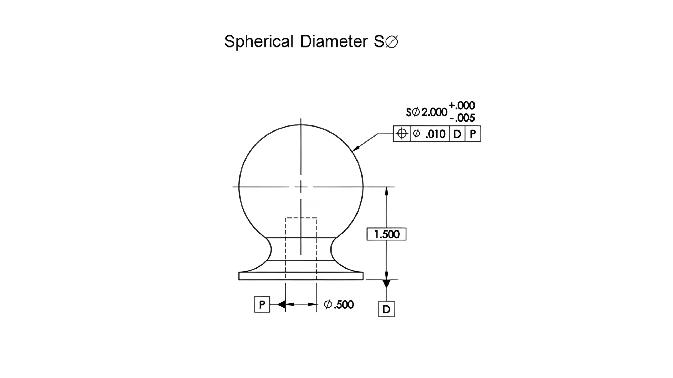
In the GD&T (Geometric Dimensioning and Tolerancing) system, S⌀ is the standard symbol used to label Spherical Diameter.
It is used exclusively for three-dimensional spheres to indicate the maximum straight-line distance through the center of the sphere, and is commonly used for spherical parts such as bearing balls, ball joints, spherical caps, and other structures.
In order to avoid confusion with the 2D circular diameter “⌀” or the spherical radius “SR”, the prefix S⌀ has been created separately to clearly characterize the dimensions of 3D spheres in drawings.
The drawing is clearly marked with “S⌀ 1.25” to explicitly denote that the sphere has a diameter of 1.25 millimeters, where the symbol “S⌀” functions as a prefix specified by the GD&T standard, exclusively used for dimensions related to spherical features.
The drawing includes the annotation “Spherical Diameter” to clearly specify that this dimension refers to a spherical diameter, differentiating it from a standard circular dimension.
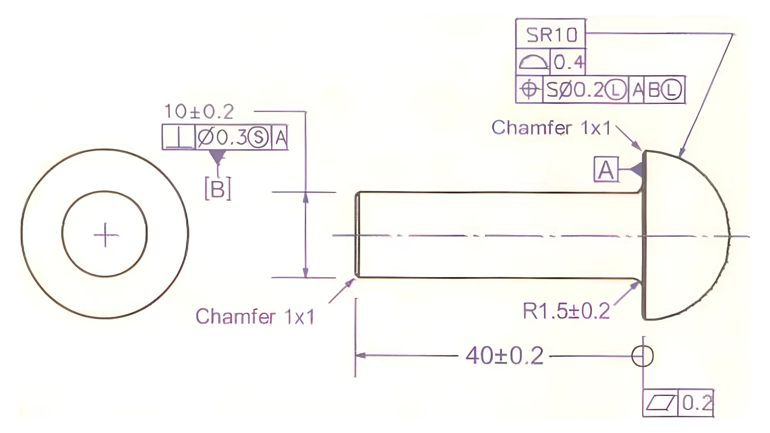
Below is Spherical Diameter Dimensioning with Datum and Tolerance Control
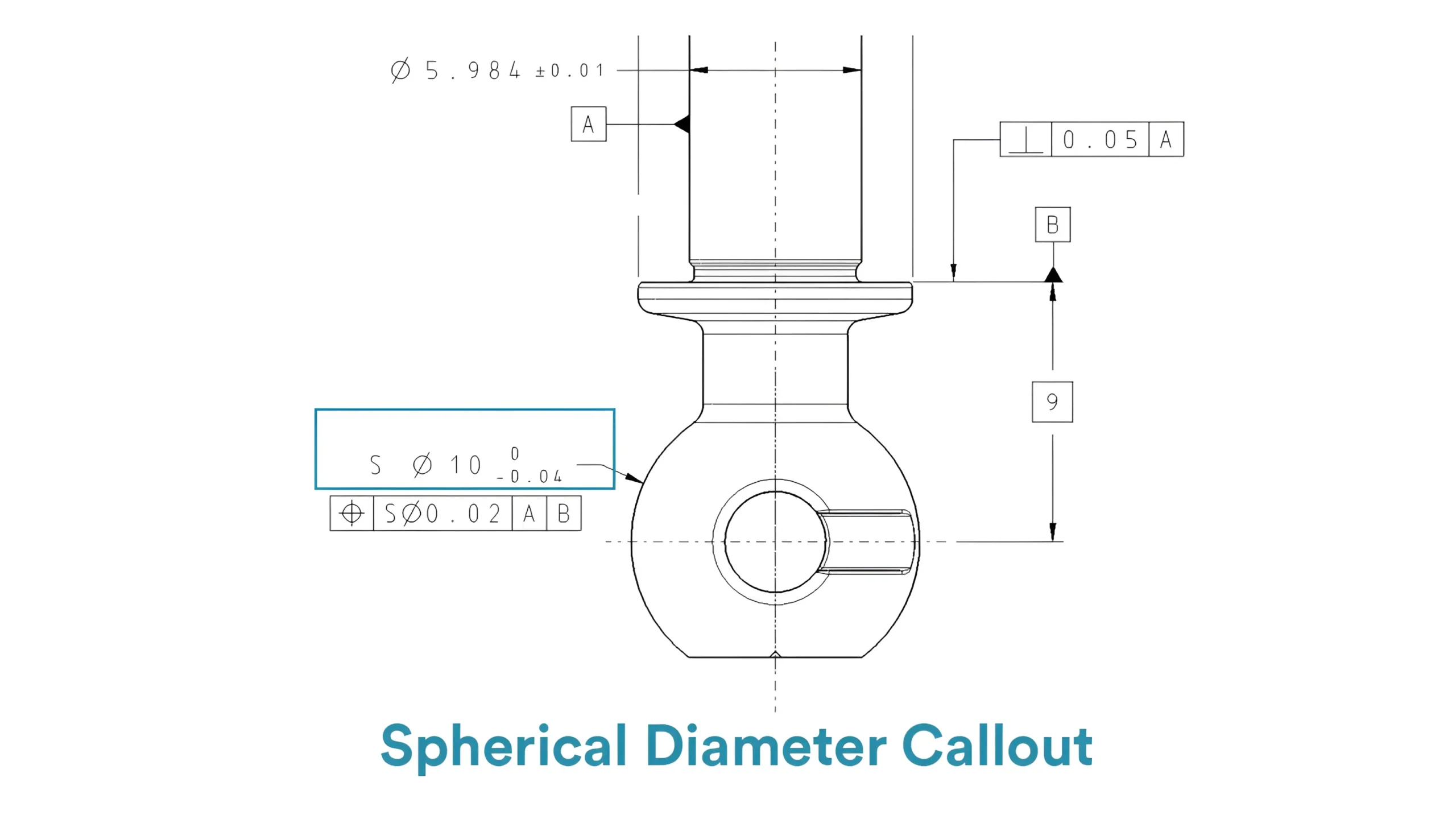 This type of labeling is a typical example of how S⌀ can be used in practical assembly scenarios for structures such as ball bearings, spherical connectors, and so on. The combined expression of S⌀ , tolerances, datum + and form control ensures that the part achieves the following during the manufacturing and assembly phases.