In the GD&T system, the Tangent Plane symbol (Ⓣ) is a key tool for solving orientation control challenges of irregular surfaces. For scenarios such as casting oxide skins and thin-walled part springback, traditional flatness tolerances struggle to precisely constrain functional performance.
Ⓣ addresses this by replacing actual surface control with a theoretical high-point fitted plane, balancing precision and feasibility.
This article, aligned with international standards, analyzes its annotation rules, machining implementation, and cross-industry applications, providing engineers with a technical framework from design to production.
This section analyzes the technical essence of Tangent Plane notation (“Ⓣ”), which “replaces actual surface control with theoretical fitting plane”, and compares the core differences between it and traditional flatness control in terms of constraint objects and application scenarios.
Combined with ASME Y14.5-2018 Clause 8.12-2018 and ISO 1101:2021, we clarify the logic of “Ⓣ” in casting billets, welded structures and other scenarios, and help readers to establish a systematic cognition of “Orientation Priority, Surface Exemption”.
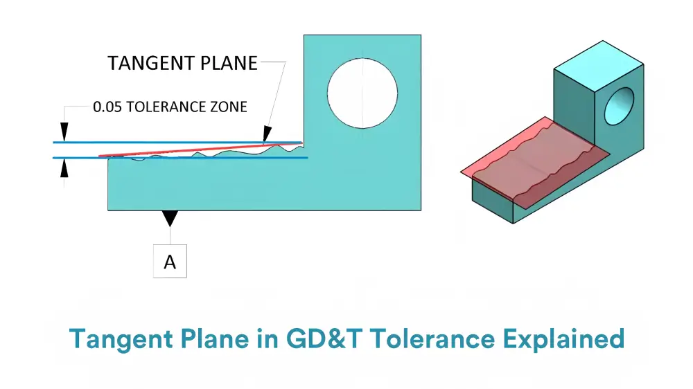
In the GD&T system, the Tangent Plane symbol (“Ⓣ”) specifies that the geometric tolerance applies to the theoretical Tangent Plane modeled by the surface highpoints, not the actual rough surface elements.
Its core function is to constrain the orientation (e.g., parallelism, perpendicularity) of a theoretically fitted plane for irregular surfaces, such as oxidized casting skins or stamped sheet metal rebound zones, where conventional flatness control is ineffective.
The standard requires a mandatory associated datum to define the direction of the tolerance band by means of a feature control box labeling (e.g., 0.05 “Ⓣ” A).
Table 1:Traditional Flatness vs. Tangent Plane Control (Ⓣ)
Dimension | Traditional Flatness Control | Tangent Plane Control (Ⓣ) |
Control Object | Full-surface undulation and roughness | Theoretically fitted plane by high points |
Core of the Tolerance Zone | Area between two parallel planes | Directional tolerance zone defined relative to datum features |
Typical Workpieces | Ground guide surfaces | Casting dies for automotive panels |
Drawing annotations serve as the critical link for transmitting Tangent Plane control requirements from the design phase to the manufacturing process.
This section disassembles the annotation structure of “tolerance + “Ⓣ” + datum”, and shows how to accurately express the Tangent Plane directional constraints through engineering cases such as engine mounts and mold parting surfaces.
For the Tangent Plane and flatness need to coexist in the scene, provide a combination of labeling solutions and conflict resolution principles, to ensure that the technical documents without ambiguity landing.
Symbol position: located in the feature control box after the tolerance value, need to be forced to associate with the benchmark.For example, the annotation ⊥ 0.03 “Ⓣ” B specifies the perpendicularity tolerance of the Tangent Plane to datum B as 0.03 mm (GD&T rule: The symbol follows the tolerance value and must be associated with a datum).
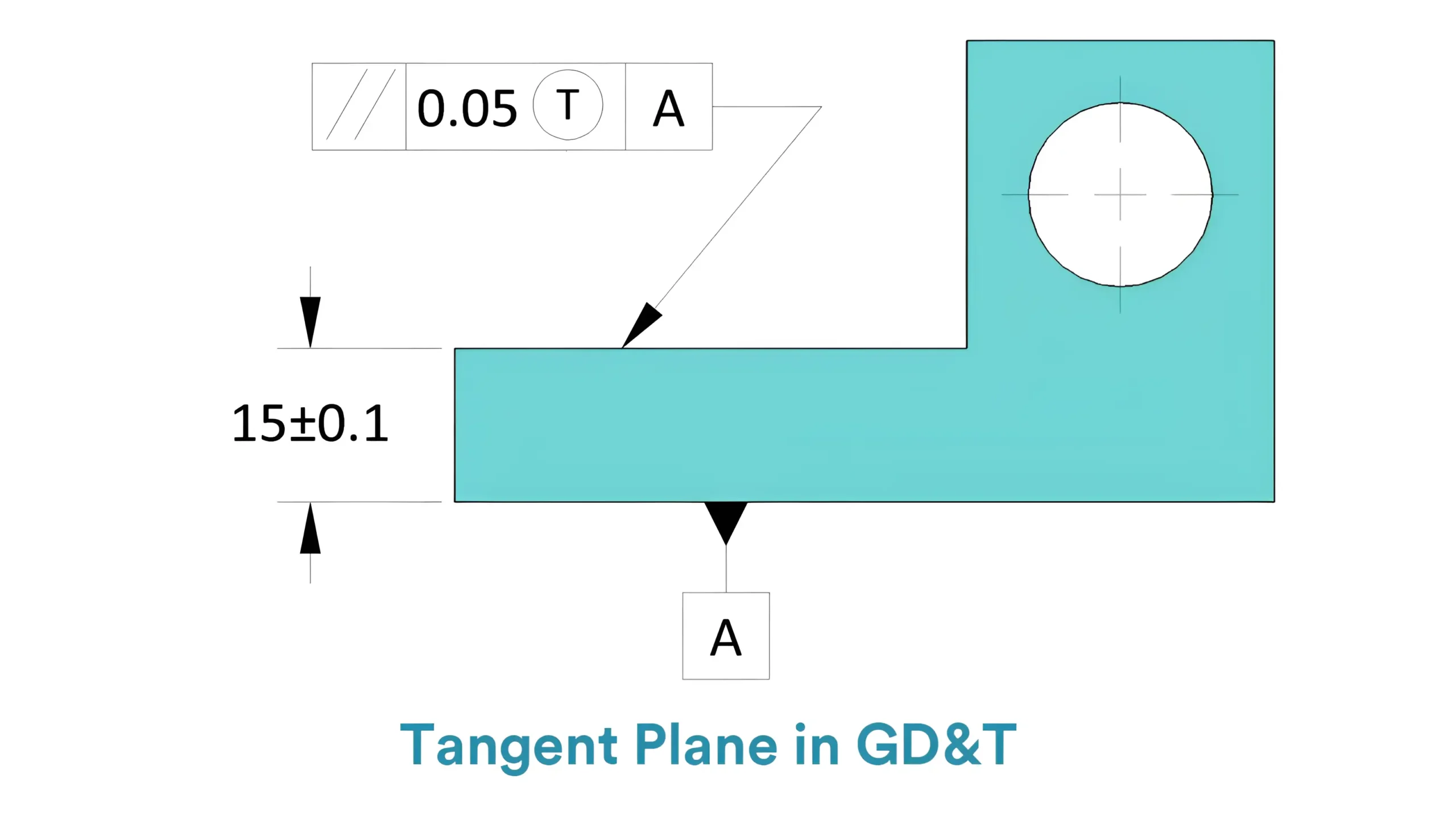
Supplementary note: State “All tolerances apply to the Tangent Plane “Ⓣ” for high point simulation” in the title bar or technical requirements to avoid misunderstanding.
Example of error: Mistakenly labeling “Ⓣ” after the datum (e.g. 0.05 A “Ⓣ”), resulting in the direction of the tolerance band not being clear.
When it is necessary to control the direction and surface undulation at the same time, the layered labeling is used:
Adopt a hierarchical labeling strategy:
① Tangent Plane parallelism control: 0.05 “Ⓣ” referenced to datum A.;
② Independent surface roughness control: 0.02 (subsequent grinding required).
Not all parts require Tangent Plane control.
This section analyzes the key signals that trigger “Ⓣ” marking from three dimensions: material characteristics (e.g., aluminum alloy elastic rebound), structural characteristics (e.g., thin-walled parts with a wall thickness of <3 mm), and functional requirements (e.g., contact accuracy of the assembly datum), and combines them with typical cases of CNC machining (e.g., aerospace titanium alloy blades and engine block blanks),to assist technicians in quickly identifying application scenarios.
Highly elastic materials: aluminum alloy thin-walled parts (deformation caused by clamping force in processing, rebound after release).
Rough surface: cast iron casting surface (Ra > 12.5 μm, random distribution of high points).
Case: A 1.5 mm-thick aluminum alloy heat sink with 0.5 mm free-state flatness is controlled to 0.08 mm Tangent Plane parallelism via the annotation 0.08 “Ⓣ” A, meeting assembly clamping requirements.
Mechanical Manufacturing: Precision Gearbox Flange Surface
For the flange surface of a high-precision gearbox, label “0.05 “Ⓣ” B” to ensure the perpendicularity of the bolt hole array relative to the datum B. This controls the assembly stress caused by surface orientation deviation, reducing gear meshing backlash by 15% and improving transmission efficiency.
Traditional flatness control fails here due to residual machining marks on the flange, while Tangent Plane Control focuses on the high-point fitted plane to meet the functional requirement of “directional accuracy priority”.
Tangent Plane control needs to be implemented throughout the entire chain of process planning, programming and inspection.
This section describes how to harmonize the machining and inspection datums through fixture design (e.g., use of CMM pins), set up a “high point follow” milling strategy in the CAM software, and set up a high density sampling criterion for inspection (≥ 5 points / 100 mm²) to form a “design – machine – verify” closed loop. Verification” closed loop.
Fixture alignment: design contour positioning pins so that the machining coordinate system is consistent with the CMM inspection datum (error ≤ 0.01 mm).
CAM Programming:
– Enable ‘High-Point Follow’ mode (Mastercam).
– Set 0.3 mm roughing margin for final fitting adjustment.
Sampling scheme: Use FARO arm laser scanning (10 pts/mm²) with PolyWorks software to apply least squares fitting on 200+ points, ensuring plane deviation ≤0.02 mm.
Example report:
Inspection Result: The perpendicularity of Tangent Plane “Ⓣ” to datum X is measured at 0.02 mm (tolerance 0.05 mm), passing the test (15 sampling points, distribution uniformity error <5%).
Different industries have specific needs for Tangent Plane control. This section explores the automotive, aviation and mold fields, analyzing cases such as engine casting bracket (“Ⓣ” control of assembly surface parallelism), titanium alloy wing forgings (vacuum adsorption to simulate high point contact),
EDM texture molds (using “Ⓣ” to ensure mold sealing), among others, while demonstrating industry-specific strategies for technology implementation.
Challenge: Uneven surface of gray cast iron bracket blank, free state assembly gap of 0.8 mm.
Solution: Applying the annotation 0.1 “Ⓣ” A with a pneumatic fixture (60 kPa pressure) to simulate high-point contact reduces the assembly gap from 0.8 mm to 0.15 mm, improving bolt preload consistency by 40%.
Process: 5-axis milling with 3D scanning optimizes high-point fitting, ensuring Tangent Plane angular tolerance within ±0.1°.
Inspection: CMM sampling at 50 points under (20±1℃) confirms fitting plane error ≤0.03 mm, meeting aerospace structural standards.
Process: 5-axis milling with Tangent Plane control (“Ⓣ”) to constrain the titanium alloy hip implant-bone interface angle within ±0.01°, combined with laser texturing for roughness control.
Standard: Conforms to ISO 13485 and ASTM F2133, ensuring traceability of geometric tolerances for osseointegration.
Use case: High-density mold cavity base reference surface controlled with “Ⓣ” to limit die flatness interface tolerance to <0.05 mm, reducing solder joint voids by 30% and complying with IPC-A-610 Class 3 specifications.
The control of Tangent Plane often encounters problems such as high point simulation deviation and team perception disagreement. This section analyzes the risks of insufficient sampling density (e.g., only 3 points lead to plane fitting distortion), labeling ambiguity (e.g., no clear datum correlation), etc., and provides solutions such as laser scanning intensive sampling, cross-departmental labeling review, and other solutions, supplemented by automotive mold project cases, to show the closed-loop process.
Risk: The traditional tactile measurement only takes 5 points, which cannot reflect the real high point distribution on the surface, resulting in the deviation of the Tangent Plane exceeding 30%.
Improvement: PolyWorks laser scanning (10 points/mm² density) with Gaussian filtering to remove outliers enhances Tangent Plane fitting accuracy from ±0.03 mm to ±0.005 mm.
Laser scanning (e.g., PolyWorks, 10 pts/mm²) with Gaussian filtering reduces fitting errors from ±0.03 mm to ±0.005 mm.
Case: The 0.05 “Ⓣ” datum was not specified in the design, and the machining team mistakenly used its own positioning surface as the datum, resulting in a batch of scraps.
Prevention: Include a constraint schematic in the drawing, mark the datum symbol and force direction, and conduct a tripartite review involving design, process, and testing teams.
Establishing enterprise-level standards for Tangent Plane applications is the key to improving quality stability.
This section suggests building a “Material – Process – Inspection” database (e.g. aluminum alloy casting “Ⓣ” tolerance empirical values), recommending tools such as PolyWorks Point Cloud Processing, GD&T Advisor Marking Verification, etc., and citing the original ASME Y14.5-2018 Clause 8.12 to make the technical bottom line clear.
Database content:
Material: cast iron parts “Ⓣ” tolerance recommended value (0.08-0.15 mm);
Fixture: pneumatic fixture pressure threshold (40-80KPa).
Training Module:
Module 1: Difference in labeling between “Ⓣ” and flatness (case comparison);
Module 2: CMM Tangent Plane inspection hands-on (virtual simulation training).
Software tools:
GD&T Advisor: automatic verification of labeling compliance (e.g., datum correlation integrity);
ANSYS Workbench: simulate the material deformation trend during Tangent Plane fitting.
Standards Citation:
ASME Y14.5-2018 Clause 8.12 (Page 78) defines the Tangent Plane symbol (Ⓣ) as controlling geometric tolerances based on a theoretical plane fitted to surface high points.
ISO 1101:2021 Clause 6.2.3 specifies that surface roughness tolerances (e.g., Ra values) can be applied synergistically with Tangent Plane control (“Ⓣ”), prioritizing assembly orientation accuracy (e.g., parallelism, perpendicularity) over full-surface roughness control
The Tangent Plane symbol (Ⓣ) breaks through the limitations of traditional surface control with its “function-driven” approach, significantly improving assembly accuracy in automotive, aerospace, and other industries (e.g., reducing casting gaps from 0.8mm to 0.15mm).
Its integration with laser scanning and simulation tools drives control from experience-based to data-driven practices. Mastering the essence of Ⓣ means establishing an efficient bridge between design and manufacturing—achieving a balance between functionality and cost by precisely constraining high-point fitted planes.
It has become a core technology for differentiated precision control in advanced manufacturing.
Lucas is a technical writer at ECOREPRAP. He has eight years of CNC programming and operating experience, including five-axis programming. He also spent three years in CNC engineering, quoting, design, and project management. Lucas holds an associate degree in mold design and has self-taught knowledge in materials science. He’s a lifelong learner who loves sharing his expertise.
Copyright © 2025 Shenzhen ECO Industrial Co.,Ltd. All rights reserved.