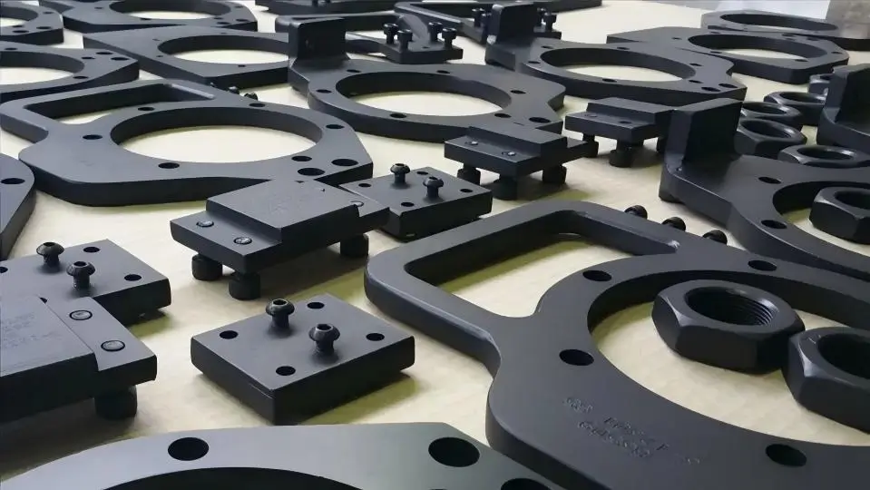
Teflon coating for CNC parts, also known as
PTFE coating for CNC components, is a high-performance surface treatment based on polytetrafluoroethylene (PTFE). It can be used in precision machined CNC parts to enhance part performance by creating a
low-friction, non-stick, heat-resistant, and corrosion-resistant surface layer.
CNC Teflon coating has become a key solution for improving reliability, reducing maintenance, and extending service life.
1. What is Teflon Coating for CNC Parts?
CNC Teflon coating refers to a process where CNC-machined metal parts are blasted, cleaned, primed, top-coated, and high-temperature cured to form a controlled-thickness (typically 20–30µm), functional coating primarily made of polytetrafluoroethylene (PTFE) or modified fluoropolymers (PFA, FEP, ETFE).
This coating achieves a low coefficient of friction (0.05–0.15), non-stick properties, chemical resistance, and continuous heat tolerance up to 240–260°C. The CNC machining stage must preserve coating allowance to avoid assembly dimension deviations.
2. Benefits of Teflon Coating for CNC Parts
The core advantage of industrial Teflon coating for CNC parts is its ability to provide self-lubrication, non-stick properties, corrosion resistance, and wide temperature stability within a thin 25–30 µm coating. This makes Teflon coated CNC parts ideal for improving reliability and achieving maintenance-free performance, especially in clean environments or applications where lubrication is not possible.
2.1 Extremely Low Friction and Self-lubricating Properties
After
Teflon coating for CNC parts—including aluminum, stainless steel, and carbon steel—the surface friction coefficient can be reduced to 0.05–0.15, with minimal difference between static and dynamic friction. This is significantly lower than steel-on-steel (~0.8) or steel-on-brass (~0.2). As a result,
Teflon coated CNC parts such as guide bushings, slides, and pistons can operate with greatly reduced—or even eliminated—external lubrication. This makes
CNC Teflon coating especially valuable in cleanroom environments, high-temperature applications, and sealed systems where regular lubrication is impractical or impossible.
2.2 Excellent Chemical Inertness and Corrosion Resistance
Teflon coating for CNC parts is highly inert and resistant to acids, alkalis, organic solvents, and most corrosive media, with the exception of molten alkali metals and high-temperature fluorine gas. For components used in chemical processing, semiconductor, medical, and food-grade environments,
Teflon coating for chemical resistance provides an effective alternative to costly stainless steel or specialty alloys. It also helps prevent galvanic and pitting corrosion, significantly extending the service life of CNC components.
2.3 Outstanding Non-Stick and Anti-Fouling Properties
Teflon coated CNC parts exhibit exceptional non-stick performance. Most solid and liquid materials—including adhesives, molten plastics, food products, and powders—have minimal adhesion to the coated surface. Typical engineering applications include:
- Mold release surfaces:Enable automatic part release without the need for release agents
- Hoppers and rollers:Prevent material buildup, reducing cleaning time by over 80%
- Fixture surfaces:Allow easy removal of residual glue or weld spatter without affecting positioning accuracy
These properties make
CNC PTFE coating ideal for applications where cleanliness and process efficiency are critical.
2.4 Wide Temperature Stability
Depending on the coating type,
Teflon coating for CNC parts provides stable performance across a wide temperature range from
-196°C to 260°C.
- PTFE / PFA coatings:up to 260°C
- FEP coating:up to 200°C
- ETFE coating:up to 150°C
This allows
Teflon coated CNC parts to operate reliably in both cryogenic environments (such as liquid nitrogen) and high-temperature, oil-free conditions. The coating remains stable without embrittlement at low temperatures or degradation at elevated temperatures.
2.5 Reduced Wear and Extended Part Life
Although PTFE coatings are relatively soft, their
low-friction characteristics significantly reduce wear on both the coated surface and mating components. This is especially important when working with softer materials such as aluminum or plastics, where scratching and galling (cold welding) are common concerns. Under high-load, low-speed conditions, and with proper surface preparation and primer application,
Teflon coating for low friction parts can outperform standard anodizing or hard chrome plating in terms of wear behavior. This results in longer service intervals and reduced part replacement frequency.
2.6 Improved Production Efficiency and Lower Maintenance Costs
By combining low friction, non-stick performance, and corrosion resistance,
Teflon coating for CNC parts delivers clear operational advantages:
- Eliminates or reduces the need for lubrication systems
- Minimizes downtime for cleaning due to non-stick surfaces
- Reduces replacement frequency through improved corrosion resistance
While the initial cost of
Teflon coating services may be higher than traditional surface treatments, the overall lifecycle cost is significantly lower—especially for critical components where maintenance is difficult or downtime is expensive.
3. Types of Teflon coating for CNC components
The four common types of industrial Teflon coating for CNC parts are PTFE, PFA, FEP, and ETFE.
3.1 PTFE Coating for CNC Components
PTFE coating for CNC parts is the most common type of Teflon coating. They offer a continuous service temperature of up to
260°C, with short-term tolerance up to
300°C. Among all fluoropolymer coatings, PTFE provides the
lowest coefficient of friction (approximately 0.05–0.10), along with excellent non-stick performance and outstanding chemical inertness. However, PTFE coatings have certain limitations, including relatively high porosity, moderate wear resistance, and low surface hardness. For this reason,
PTFE coating for CNC parts is best suited for applications that require extremely low friction rather than high coating density or scratch resistance. Typical applications include light-load slide rails, guide bushings, valve spools, and mold release surfaces.
3.2 PFA Coating
PFA coatings are chemically similar to PTFE, but unlike PTFE, they melt and flow during high-temperature curing, forming a dense, nearly pinhole-free film. With a continuous service temperature of up to
260°C, PFA offers improved mechanical strength, toughness, and creep resistance compared to PTFE. The resulting coating is smoother and more uniform, making
PFA coating for CNC parts ideal for demanding applications that require both non-stick performance and resistance to mechanical stress or media permeation. Typical uses include chemical reactor linings, high-temperature valve seats, and semiconductor equipment components.
The main disadvantage of PFA coatings is their higher cost compared to PTFE.
3.3 FEP Coating
FEP coatings also melt and flow during the curing process, forming a smooth, non-porous surface. With a continuous service temperature of up to
200°C, FEP performs lower than PTFE and PFA in terms of heat resistance. In terms of
non-stick performance and chemical stability, FEP is comparable to PFA, but its maximum operating temperature is lower. For CNC applications,
FEP coating for parts is well-suited for medium-temperature environments, such as rollers, printing cylinders, food processing equipment, and other components that require a dense, protective coating without the need for 260°C resistance. FEP also exhibits excellent flow characteristics during application, resulting in a smooth, high-gloss finish. In general,
FEP coatings are more cost-effective than PFA, making them a practical choice for many industrial applications.
3.4 ETFE Coating
ETFE coating for CNC parts offers excellent mechanical strength and toughness, making it the most durable among common fluoropolymer coatings. Although it has a lower continuous service temperature of 150°C compared to PTFE, PFA, and FEP, it provides superior resistance to impact, abrasion, and cutting. ETFE also maintains strong chemical resistance and non-stick properties, while delivering reliable performance in demanding industrial environments. It is widely used in applications such as conveyor systems, wear-resistant liners, and powder handling equipment, where mechanical durability is critical.
| Type | Heat Resistance | Friction Coefficient | Strength | Application Positioning |
|---|
| PTFE | ⭐⭐⭐⭐⭐ | ⭐⭐⭐⭐⭐ | ⭐⭐⭐ | Industrial mainstream |
| FEP | ⭐⭐⭐ | ⭐⭐⭐⭐ | ⭐⭐⭐ | Smooth & corrosion protection |
| PFA | ⭐⭐⭐⭐⭐ | ⭐⭐⭐⭐ | ⭐⭐⭐⭐ | High-end applications |
| ETFE | ⭐⭐ | ⭐⭐⭐ | ⭐⭐⭐⭐⭐ | High strength |
4. Teflon Coating Process for CNC Components
Below is a standard engineering workflow for
Teflon coating on CNC parts, presented in process sequence.
Step 1: Incoming Inspection and Dimensional Measurement
Before applying
Teflon coating for CNC parts, a thorough incoming inspection is performed. This includes visual inspection and critical dimensional measurements to confirm there are no burrs, dents, or surface defects. Key dimensions—such as mating surfaces, bore diameters, shaft diameters, and flatness—are measured using calibrated instruments and recorded as baseline data. These measurements are essential for coating thickness control and post-coating inspection.
Step 2: Masking
Areas that must not be coated are carefully masked to ensure dimensional and functional accuracy. Typical masking zones include threaded holes, dowel pin holes, precision mating surfaces, electrical contact areas, and assembly-critical shoulders or end faces. Masking materials must withstand high curing temperatures (up to approximately 260°C). Common solutions include high-temperature tapes, silicone plugs, and custom metal fixtures. Proper masking ensures sharp edges and prevents coating creep into non-coated regions.
Step.3 Surface Pretreatment (Sandblasting)
Prior to coating, sandblasting is used to create a controlled surface roughness, improving mechanical adhesion of the coating. Typical blasting media include aluminum oxide (white or brown) and glass beads, with grit size selected based on material and application requirements. The target surface roughness is generally
Ra 2–3 µm, with a uniform matte finish. After blasting, the surface must be free of scale, rust, or contaminants. Clean, dry compressed air is used to remove all residual dust.
Step 4: Cleaning and Degreasing
After blasting, the surface becomes highly sensitive to contamination such as oil, dust, or fingerprints. Therefore, strict cleaning and degreasing are required before coating. Common methods include ultrasonic cleaning, vapor degreasing, or thermal baking. The surface must be completely free of oil and moisture. A
water break test can be used to verify cleanliness: deionized water should spread evenly across the surface without breaking into droplets. After cleaning, operators should avoid direct contact with the surface and use clean gloves.
Step 5: Primer Application
The primer layer is critical for adhesion between the substrate and the
Teflon coating system. It also provides initial corrosion protection. The primer is typically applied via air-atomized or electrostatic spray. The recommended dry film thickness is
12–18 µm. After application, the part is pre-baked at
80–120°C for 5–10 minutes to remove solvents and prevent defects such as bubbling during final curing. The primer layer must be uniform, continuous, and free of defects such as pinholes or sagging.
Step 6: Teflon Coating Spray Process
The topcoat determines the final properties, including non-stick performance, low friction, and chemical resistance. The coating is applied using an air-atomized spray system to ensure uniform coverage. The recommended dry film thickness is
12–15 µm, resulting in a total coating thickness of approximately
25–30 µm.
For multi-layer systems, intermediate low-temperature baking may be used to improve solvent evaporation. After application, the coating should appear smooth, uniform in color, and free of defects such as orange peel, particles, or runs.
Step 7: High-Temperature Cure
Curing is a critical step in
Teflon coating for CNC parts, as it allows the coating to melt, flow, and bond with the substrate. Important: curing temperature refers to the
actual part temperature, not just the oven setting. Typical curing parameters:
- PTFE / PFA:193–199°C (380–390°F)
- FEP:182–193°C (360–380°F)
- ETFE:149–160°C (300–320°F)
Parts are held at the target temperature for
5–8 minutes, then allowed to cool naturally. Rapid cooling or quenching should be avoided, as it may cause cracking or delamination.
Step 8: Quality Inspection
After curing, a full inspection process ensures coating quality and dimensional accuracy:
- Visual inspection:No bubbles, sagging, bare spots, cracks, or contamination
- Film thickness:Measured using magnetic or eddy-current gauges (target: 25 ± 5 µm, minimum ≥20 µm)
- Adhesion test:Cross-cut tape test (ASTM D3359), no coating removal allowed
- Pinhole testing:Spark tester for applications requiring full insulation—no breakthrough permitted
- Dimensional check:Confirm coating thickness increase of approximately 0.025–0.035 mm per side, within drawing tolerance
Step 9: Packaging and Delivery
After passing all inspections,
Teflon coated CNC parts are carefully packaged to prevent damage or contamination during transportation. Typical packaging methods include foam separators, anti-static bags, and custom trays. Each part is labeled with:
- Part number
- Coating type
- Production date
- Inspection status
A quality inspection report is provided to ensure full traceability and customer confidence.
5. Teflon Coating Thickness and Tolerance for CNC Parts & Design Considerations
5.1 Coating Thickness Range and Typical Values
For
Teflon coating on CNC parts, the typical dry film thickness is controlled within
20–30 µm, depending on coating type, number of layers, and application requirements. A standard two-layer system includes:
- Primer:12–18 µm
- Topcoat:12–15 µm
- Total thickness:25–30 µm
For
PTFE coatings, a three-layer system is sometimes used to reduce the risk of pinholes, with total thickness reaching
30–40 µm. In contrast,
ETFE coatings may reach
30–50 µm in a single layer due to their higher mechanical strength. It is important to note that
thicker coatings are not always better. Excessive thickness can lead to poor leveling, wrinkling, reduced adhesion, and increased dimensional deviation.
5.2 Thickness Uniformity Control
Coating uniformity is critical for both function and assembly accuracy in
Teflon coated CNC parts.
- For rotational parts (shafts, rollers): rotate at a constant speed during spraying, keeping circumferential variation within ±5 µm
- For flat or complex geometries: ensure 50% spray overlap to avoid uneven buildup
- Measurement: use magnetic or eddy-current gauges with at least 5 measurement points (edges, center, and features)
- For mating surfaces: thickness deviation should be controlled within ±3 µm
5.3 Tolerance Compensation and Coating Allowance
Since Teflon coating forms a solid film after curing, CNC machining must account for coating thickness in advance.
Standard coating allowance:- External surfaces (male features):subtract 025–0.035 mm per side
- Internal surfaces (female features):add 025–0.035 mm per side
Example: A shaft specified as φ20 h7 should be pre-machined to approximately φ19.97 ± 0.01 mm. After coating, the final dimension will fall within tolerance. If coating allowance is not properly reserved, post-coating machining is possible but generally not recommended, as it may damage the coating and compromise adhesion.
5.4 Design Strategy for Critical Mating Surfaces
For precision-fit components, proper design strategy is essential when using
Teflon coating for CNC parts:
- Strategy 1 (Preferred):Coat only one mating surface, leave the other uncoated, and define final dimensions after coating
- Strategy 2:Use coating only for non-mating surfaces (anti-stick or corrosion protection), and mask all precision areas
- Strategy 3:Apply coating first, then machine or grind to final dimensions (achieves highest precision, ±0.005 mm, but increases cost and complexity)
5.5 Special Considerations for Threads and Holes
Threads and precision holes require special attention when applying
Teflon coating:
- Threads are generally maskedto avoid dimensional changes
- Coating inside threads may affect fit and torque
- For corrosion protection, re-tapping after coating is possible, but may damage coating edges
- Holes smaller than 5 mm should always be masked to prevent clogging
- For larger through-holes (>10 mm), coating may be allowed, but tolerances must be clearly specified (typically +0.05 mm per side)
5.6 Thermal Expansion Matching
Teflon (PTFE) has a relatively high coefficient of thermal expansion (
100–150 × 10⁻⁶ /°C) compared to common metals:
- Aluminum: ~23 × 10⁻⁶ /°C
- Stainless steel: ~17 × 10⁻⁶ /°C
- Carbon steel: ~12 × 10⁻⁶ /°C
This mismatch means that during temperature changes,
Teflon coating and the substrate expand at different rates, which can create internal तनाव (stress) and potentially lead to cracking or delamination over time. For applications with wide temperature variation:
- Prefer aluminum substrates when possible
- Reduce coating thickness if using steel
- Use appropriate primer systems to improve stress absorption
5.7 Edge and Corner Treatment
Sharp edges are prone to coating failure, including thinning, pull-back, or peeling. To improve coating performance in
Teflon coated CNC parts, design features should include:
- Chamfer:3–C0.5 mm
- Radius:3–R0.5 mm
Avoid coating sharp edges whenever possible. For deep grooves or narrow features:
- Minimum slot width: ≥5 mm
- Maximum depth: ≤10 mm
Otherwise, consider alternative strategies such as masking or post-assembly coating.
5.8 Drawing Notation for Teflon Coating
Clear engineering drawings are essential to avoid misinterpretation in
Teflon coating for CNC manufacturing. A complete drawing should include:
- Coating type (PTFE, PFA, FEP, or ETFE)
- Total dry film thickness (e.g., 25 ± 5 µm)
- Coating area (clearly indicated)
- Masked areas (labeled “No Coating”)
- Final dimensions after coating (with note “After Coating”)
Example note: SURFACE TREATMENT: PTFE COATING, TYPE I, 25 ± 5 µm DRY FILM THICKNESS, PER ASTM D4895. MASK THREADED HOLES AS SHOWN. FINISH DIMENSIONS AFTER COATING SHALL BE PER DRAWING.
5.9 Design Recommendations
- Integrate coating thickness into tolerance stack-up during the design stage
- Coat the component that is easier and more cost-effective to replace
- For high-precision fits (IT6 or better), always include coating allowance and final inspection after coating
- Run pilot samples before mass production to verify fit and coating thickness
- Communicate early with your Teflon coating service providerregarding thickness capability, masking strategy, and inspection methods
Early collaboration significantly reduces risk and ensures consistent, high-quality results for
CNC Teflon coated parts.
6. Suitable Materials for Teflon Coating (PTFE Coating)
Not all materials are ideal for PTFE (Polytetrafluoroethylene) coating. The performance of a Teflon coating largely depends on the substrate’s
thermal stability, surface energy, coefficient of thermal expansion (CTE), and surface preparation capability. These factors directly impact adhesion strength, coating durability, and long-term performance. Below is a practical, engineering-focused guide to commonly used substrates in CNC and industrial applications.
6.1 Teflon Coating on Aluminum
Aluminum is the
most widely used and best-performing substrate for PTFE coating.
 Why aluminum works well:
- Lightweight with excellent machinability
- Moderate coefficient of thermal expansion (~23×10⁻⁶/°C)
- Relatively closer to PTFE (100–150×10⁻⁶/°C), reducing stress during thermal cycling
- Excellent adhesion after proper surface preparation
Common aluminum grades:- 6061 aluminum
- 7075 aluminum
- 5052 aluminum
- 5083 aluminum
Important considerations:- Cast aluminum (e.g., A380) may contain porosity or gas pockets
→ Requires aggressive blasting, deep cleaning, or machining off the cast skin
- Anodized aluminum is NOT suitable for direct PTFE coating → Adhesion is poor; the anodized layer must be removed before coating
- Recommended process: bare aluminum → blasting → cleaning → primer → PTFE coating
Teflon coating aluminum parts is the most common application in CNC machining due to its excellent adhesion and dimensional stability.6.2 PTFE Coating on Stainless Steel
Stainless steel is another
high-performance substrate for PTFE coating, widely used in chemical, food, and medical industries.
Suitable stainless steel grades:- 304 stainless steel
- 316 stainless steel
- 316L stainless steel
- 17-4PH stainless steel
- 420 stainless steel
- 430 stainless steel
Key advantages:- High corrosion resistance
- Dense surface structure for uniform blasting
- Ideal for non-stick and low-friction applications
Engineering notes:- CTE (~17×10⁻⁶/°C) differs more from PTFE than aluminum
→ Still acceptable, but requires good coating design
- Harder grades (e.g., 440C) are more difficult to blast
- Sandblasting is mandatoryfor proper adhesion
Typical applications:- Food processing components
- Chemical handling parts
- Medical and pharmaceutical equipment
6.3 PTFE Coating on Carbon Steel
Carbon steel and alloy steel can be coated, but require
strict process control.
Common materials:- Q235 steel
- 45 steel
- 40Cr steel
- 42CrMo steel
Key challenges:- Rapid oxidation after blasting
→ Surface may rust within hours
- Lower CTE (~12×10⁻⁶/°C)
→ Greater thermal mismatch with PTFE
- Higher risk of cracking or delamination under thermal cycling
Best practices:- Apply coating within 2–4 hours after blasting
- Use inline blasting + immediate coatingfor critical parts
- Apply anti-corrosion primerbefore PTFE topcoat
- Verify surface condition (no nitriding, carburizing, or chrome plating)
PTFE coating on carbon steel is cost-effective but requires strict surface control to ensure coating durability.6.4 Materials Not Suitable for Teflon Coating
Some materials are
not compatible with PTFE coating due to thermal, chemical, or adhesion limitations:
6.4.1 Magnesium Alloys
- High chemical reactivity
- Fire risk during blasting
- Oxidation or ignition risk during curing (~200°C)
→ Not recommended
6.4.2 Plastics and Composites
- Examples: nylon (PA), acetal (POM), carbon fiber composites
- Insufficient heat resistance (typically <150°C)
→ Cannot withstand PTFE curing temperature
- Surfaces with hard coatings
- Nitriding, carburizing, chrome plating, anodizing
→ Poor bonding with PTFE primer
→ Must be completely removed before coating
6.4.3 Zinc and zinc alloys
- Low melting point
- Prone to blistering during curing
→ Not suitable for PTFE processes
6.5 Critical Surface Preparation Requirements
Based on practical experience with Teflon coating services, regardless of substrate, the following surface conditions must be met before coating: Surface roughness Ra 2–3µm, achieved by white or brown aluminum oxide blasting, with pressure and media size adjusted for substrate hardness. Cleanliness: oil-free, grease-free, dust-free, fingerprint-free – verified by water break test (continuous water film for >10 seconds without breaking). No existing coating, scale, rust, or plating on substrate – must be removed by machining or chemical methods. For large or complex parts, apply primer within 4 hours after blasting to prevent surface contamination or flash rusting.
7. Applications of Teflon-coated CNC Parts
In the CNC machining, Teflon coating is used primarily to reduce friction, enhance corrosion resistance, provide non-stick properties, and extend service life. Different applications have different performance requirements, so the applicable part types are very specific.
| Requirement Type | Core Reason | Typical Parts |
|---|
| Oil-Free Self-Lubrication | Liquid lubricants cannot be used (cleanroom, high temperature, vacuum environments) | Slide rails, slides, bearings, bushings, pistons, guide sleeves |
| Anti-Stick / Easy Demolding | Material adhesion to metal surface affects demolding or production continuity | Injection molds, die-cast molds, hot press molds, lost foam molds |
| Chemical Corrosion Resistance | Exposure to strong acids, strong alkalis, organic solvents; ordinary metals are not corrosion resistant | Reactor vessel inner walls, valves, pump bodies, pipe liners, electroplating racks |
| Non-Stick / Easy Cleaning | Food, pharmaceutical, powder processing scenarios requiring easy residue removal | Food conveyor rollers, cutting blades, hopper inner walls, agitator paddles |
| High Temperature Resistance / Wide Temperature Range | Wide operating temperature range (-196°C to 260°C); coating must not fail | Oven internal components, heat treatment fixtures, liquid nitrogen environment parts |
| Electrical Insulation | Insulation, arc resistance, anti-static required | Insulating brackets, electrode protectors, semiconductor equipment parts |
| Protection of Mating Parts | Mating part is made of soft material (aluminum, plastic); prevent scratching or cold welding | Guide surfaces, sliding mating surfaces, solenoid valve cores |
8. Teflon vs Anodizing vs Powder Coating| Comparison Aspect | Teflon (PTFE) | Anodizing | Powder Coating |
|---|
| Primary function | Non-stick, low friction, chemical resistance | Improve corrosion resistance, decorative | Corrosion protection, decorative, wear enhancement |
| Friction coefficient | ⭐ Extremely low (~0.05–0.1) | ⭐ Higher (depends on surface) | ⭐ Moderate |
| Wear resistance | ⭐ Moderate (depends on system) | ⭐⭐ Good (hard anodizing better) | ⭐⭐⭐ Good |
| Corrosion resistance | ⭐⭐⭐⭐ Excellent (chemical resistant) | ⭐⭐⭐⭐ Excellent (especially on aluminum) | ⭐⭐⭐ Good |
| Appearance | Matte / black / gray | Multiple colors (dyeable) | Wide color range (decorative) |
| Coating thickness | 5–150 μm | 5–50 μm | 50–150 μm |
| Dimension impact | Moderate (requires预留) | Very small | Large (thick coating) |
| Heat resistance | ⭐⭐⭐⭐ High (~260°C) | ⭐⭐⭐⭐ High | ⭐⭐ Moderate (~150–200°C) |
| Electrical insulation | ⭐⭐⭐⭐ Excellent | ⭐⭐⭐⭐ Excellent | ⭐⭐ Moderate |
| Applicable materials | Primarily metals | Primarily aluminum | Metals (steel/aluminum) |
| Non-stick property | ⭐⭐⭐⭐⭐ Very strong | ❌ No | ❌ No |
| Typical applications | Molds, sliding parts, food machinery | Aluminum housings, electronics | Housings, structural parts, industrial components |
Teflon (PTFE coating) makes surfaces slicker and non-stick.
Anodizing makes aluminum more corrosion-resistant and aesthetically pleasing.
Powder coating provides a thicker, tougher, more decorative surface. Suggestions about the selection.
- Choose Teflon coating for CNC parts when you need low friction, non-stick performance, food contact/mold release applications, or chemical resistance environments. Keyword: most functional.
- Choose anodizing when you need surface protection for aluminum parts, high aesthetic appearance (black or colored), or for electronic housings. Keywords: lightweight, aesthetic, corrosion protection.
- Choose powder coating when you need a low-cost, wear-resistant, appearance-oriented treatment. Keywords: economical, general-purpose.
10. FAQ
10.1 What is the thickness of Teflon coating on CNC parts?
The standard two-layer Teflon (PTFE) coating system, consisting of a primer and topcoat, typically has a total dry film thickness of
25–30 µm (primer: 12–18 µm, topcoat: 12–15 µm). For PTFE applications requiring improved coating integrity (e.g., reduced pinholes), a
three-layer system may be used, resulting in a total thickness of
30–40 µm. For ETFE coatings, a
single-layer thickness of 30–50 µm is common due to higher mechanical strength requirements. Typical thickness tolerance is
±5 µm, while critical or mating surfaces may require tighter control of up to
±3 µm. Excessive thickness is not recommended, as it can lead to poor leveling, wrinkling, and reduced adhesion performance.
10.2 Does Teflon coating affect part tolerance?
Yes. Teflon (PTFE) coating adds measurable thickness and must be included in the
tolerance stack-up during part design and machining. The coating builds up on all exposed surfaces. For a typical total thickness of
30 µm, the
single-side buildup is approximately 0.015 mm. Without proper allowance, final dimensions may exceed drawing tolerances.
Standard machining practice:- External surfaces: machine to basic dimension −0.03 mm
- Internal features (holes, bores): machine to basic dimension +0.03 mm
This ensures the final dimensions meet specification after coating. If no coating allowance is provided, post-coating machining may be required to remove excess thickness. However, this approach
breaks coating continuity and compromises performance, and is generally not recommended.
10.3 Is Teflon coating durable?
Yes. With proper substrate preparation, the correct primer, and a coating system matched to the application, Teflon (PTFE) coating can provide excellent durability. When applied using a qualified process, PTFE coating on carbon steel or aluminum offers reliable performance for
low-friction and non-stick applications. However, Teflon coatings have
moderate scratch and abrasion resistance compared to harder finishes such as hard anodizing or powder coating. For applications involving higher wear, abrasion, or impact,
ETFE coating is typically a more durable alternative.
10.4 Is Teflon coating heat resistant?
Yes. PTFE and PFA coatings are continuously heat resistant up to 260°C, with short-term tolerance to 300°C. FEP is heat resistant to 200°C, and ETFE to 150°C. Teflon coated CNC parts can operate from cryogenic temperatures (-196°C) up to these limits without embrittlement or melting.
10.5 Can Teflon coating peel off?
Teflon (PTFE) coating can peel or delaminate if the substrate is not properly prepared. Common causes include
insufficient sandblasting, residual oil or contamination, incorrect primer selection, or excessive coating thickness. However, when proper surface preparation is followed—including thorough sandblasting, rigorous cleaning, use of the correct primer, and controlled curing—
coating adhesion is strong, and peeling should not occur under normal service conditions. In practice, coating failure is more commonly caused by
mechanical abrasion or impact, rather than spontaneous delamination.
10.6 How long does Teflon coating last?
Service life depends on application conditions, including
load, speed, temperature, chemical exposure, and mating materials. In low-friction, non-abrasive applications (such as mold release or light-load sliding), Teflon (PTFE) coating can last for
years or tens of thousands of cycles. In higher wear or more demanding conditions, service life will be reduced.
10.7 Is Teflon coating expensive?
Per-part cost for Teflon (PTFE) coating is generally higher than traditional finishes such as painting or anodizing, due to multiple process steps—including
blasting, cleaning, primer application, topcoat, curing, and quality control. However, when evaluated over the full lifecycle, Teflon coating often delivers
overall cost savings. Benefits include reduced lubrication requirements, less cleaning downtime, and lower replacement frequency due to improved corrosion and wear resistance—especially for critical or hard-to-maintain components. For high-volume production, working with an experienced Teflon coating supplier can further
optimize cost and consistency for custom CNC parts.