Just like the world cannot run without the cooperation of each factor, machines cannot run and function well without good fitting between mating parts. Engineer fit is an important technical concept for the field of mechanical construction.
It focuses on the accurately calibrated dimensions and clearances between two matching components, chasing for the precise alignment and integration of these features.
According to the size of clearances, engineering fits are generally classified into three types, including interference fit, clearance fit and transition fit.
Since right fits play a crucial role in ensuring proper assembly and functionality, distributing loads and stresses, and lengthening running of machines, every manufacturer is supposed to know how to choose right engineering fits.
This article provides particular information about the concept of engineering fits and the types of fits, as well as considerations to choose right engineering fits.
As a part of Geometric and Dimensioning & Tolerancing(GD&T), engineering fits play a critical role during the process of the feature or assembly design.
The word “fit” refers to the amount of clearance and degree of contact between mating parts, aiming to make them joint temporarily or permanently, and slide or rotate independently to some extent.
As both ISO and ANSI classifying, there are three types of fits in mechanical engineering: interference fits, clearance fits and transition fits. The choice of fits is typically made during the design phase, based on the requirements for the mating parts.
Interference fits make the features joint tightly and be able to carry high loads.
While clearance fits allow a slight gap between the mating parts, making the components be able to slide or rotate as required.
As for transition fits, whose dimensions of clearance are between that of interference fits and clearance fits, are characterized by joints that carry sufficient force to maintain contact but cannot bear high loads.
The hole and shaft basis system is the foundational standard for engineering fits, defining the relationship between the basic size and tolerances of mating parts.
The system fixes the size of either the hole or the shaft as a reference, while the other mating component changes the size within specified tolerances. It is composed with two system: the hole basis system and the shaft basis system.
In the hole basis system, the size of the hole is fixed while that of the shaft varies to achieve the required fits. Generally, the hole basis system is more popular for the dimensions of shaft are easier to control than that of hole.
And the CNC turning services can manufacture shafts with precise dimensions, making it more convenient to achieve the desired fits.
Advantages of the Hole Basis System:
Contrast to the hole basis system, it is the dimensions of the shaft that is fastened in the shaft basis system, meanwhile the sizes of hole vary based on the fits as needed.
This system would get favor when the design or sizing of shaft is difficult to control, or the material is hard to alter.
Advantages of the Shaft Basis System:
The ISO system uses an alpha-numeric code to indicate the tolerance ranges of engineering fits, in which capital letters refer to the hole tolerances while the lowercase letters refer to the shaft tolerances.
For example, for H7/h7, a widely used fit, the H7 describes the tolerance scope of the hole, and the h7 is for the shaft.
The below two videos shows clearance fit and interference fit.
As mentioned above, there are three main types of fits in engineering, interference fit, clearance fit and transition fit. Each of them has its own specialized mechanical contact and undertakes different functions. Here we will talk about the three types of fits in detail.
The interference fit definition can be easily understood through its name “interference”. Because the tight fitting between the mating features need the interference of external force like hammers or hydraulic press.
The shaft is lager than the hole, so the shaft must be forced or pressed into the hole, and then the high frictional force tightly holds the mating features together. That is why interference fit is also called friction fit.
In addition, one of the most common techniques to achieve interference fits is shrink-fitting.
Under this technique, one of the mating features would be either cooled or heated to become smaller or larger(respectively) for a moment so that the negative clearance would be positive clearance until the two mating parts hold as required.
And when the temperature become normal, the once shrunk or expanded part also become normal, and then the interference fit is got.
In general, the clearance in an interference fit is -0.001mm to -0.042mm. Below is the sub-categories of interference fits:
Press Fit: It is the light interference fit with minimal negative clearance for medium-strength joints, usually got through cold pressing. In press fit interference tolerance table, you can see H7/p6 on the hole basis, and P7/h6 on shaft basis.
Driving Fit: It is the medium interference fit that can carry loads, needing force or cold/hot pressing to achieve. The hole basis has H7/s6 while the shaft basis has S7/h6.
Forced Fit: It is the strongest engineering fit, requiring tight cold/hot pressing and can hold tightly almost for permanent. Note that such an assembly need careful tolerancing and placement to avoid breakage. The forced fits includes H7/u6 for hole basis and U7/h6 for shaft basis.
A clearance fit have a positive clearance, showing that there is a small gap between the mating features. Example of clearance fit can be the pin and frame in pivot joints, allowing both of them to move free to some extent and meanwhile stay locked in place.
The usual range of clearance of these fits is +0.025mm to +0.089mm. Below is the sub-categories of clearance fits:
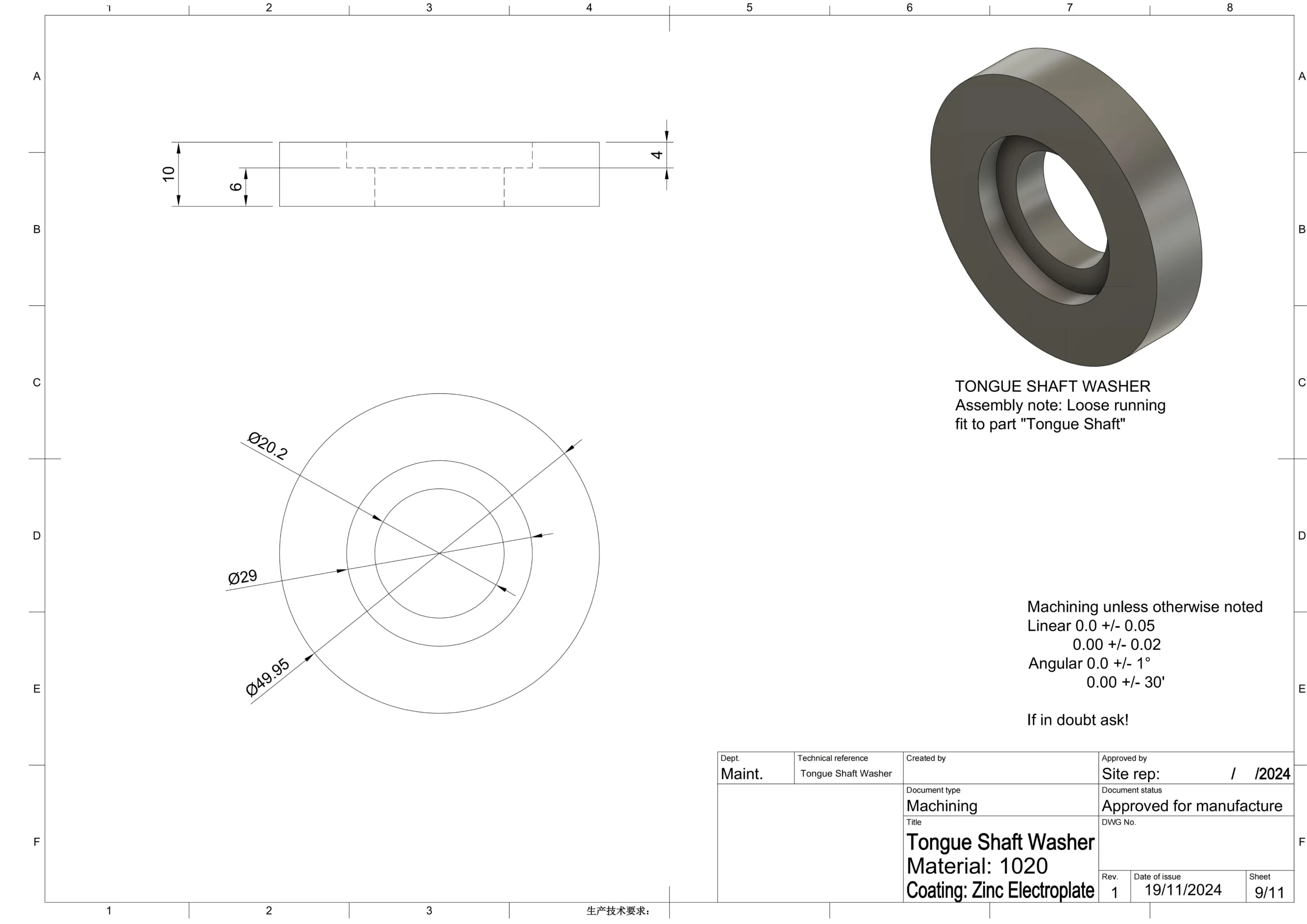
Loose Running Fit: It is a clearance fit with the largest clearance. With an observable gap between parts, features within loose running fits are free to rotate or slide.
Loose running fits are often used in position where precision does not matter so much, like pivots, latches, and parts affected by corrosion, heat, or contamination. The hole basis with H11/c11, H11/a11, and H11/d11, and the shaft basis with C11/h11, A11/h11, D11/h11 are included in this type of fits.
Free Running Fit: Similar to loose running fits, free running fits are not required special precision. Parts under this fit can move at high speed and the joint can allow huge temperature variations.
It is usually applied in applications where maintaining a film of oil lubrication is critical. The hole basis of this fits includes H9/d9, H9/c9, H9/d10, and shaft basis covers D9/h9, D9/h8, D10/h9.
Close Running Fit: This kind of fit has slightly more moderate accuracy. It can bear high running speed and journal pressures, generally used in shafts, spindles, sliding rods, and machine tools.
The hole basis with H8/f7, H9/f8, H7/f7 and shaft basis with F8/h6, F8/h7 are covered by this type of fits.
Sliding Fit: It leaves minimal clearance and is the engineering fit with high precision. Parts manufactured under sliding fit tolerance can be assembled easily and can turn or slide freely and independently.
Sliding fits are widely used in shafts, sliding gears, crankshaft journals, automobile assemblies, clutch discs, slide valves, parts of machine tools, etc. Tolerance for sliding fit covers H7/g6 and H8/g7 in hole basis and G7/h6 in shaft basis.
Location Fit: It is the close sliding fit with high requirement for precision to locate the mating features accurately. Location fit has very low clearance and can move smoothly only with the help of lubrication. In this type of fits, the hole basis is H7/h6 and shaft basis is H7/h6.
Transition fits fall between the interference fits and the clearance fits. Based on the application, the mating features are allowed to have either a slight interference or clearance.
However, compared with the former two types of fits, this kind of fits require tighter control on precision.
Typically, transition fits play a crucial role in precision-locating parts in assembly operations. The fit restricts the parts to move relatively while also avoids extreme mechanical presses.
The mechanical interference/clearance in transition fit is set between +0.023mm to -0.018mm. Below is the sub-categories of transition fits:
Similar Fit: It is a very light engineering fit with nearly zero interference or clearance. In general, using a rubber mallet by a person is enough to achieve this fit. For similar fits, the hole basis covers H7/k6, and the shaft basis covers K7/h6.
Fixed Fit: This type of fit also has very small interference or clearance like similar fit, but is slightly tighter so it needs light pressing force to achieve. Fixed fit includes H7/n6 for hole basis and N7/h6 for shaft basis.
To ensure the features manufactured accurately achieving those requirements of engineering fits, it is important to know the tolerances for them deeply and use them correctly.
The two most popular standards for engineering fits are ISO 286 and ANSI B4.1. Both of them provide comprehensive information on ranges of tolerances for different types of engineering fits.
Check thebasis of fitting selection/dimensional tolerances and fitting table below. You can also download the chart below.
Type of Fit | Hole Basis | Shaft Basis | Fit Type | Applications |
Clearance Fit | H11/c11 | C11/h11 | Loose Running Fit | Pivots, parts with corrosion and dust, parts exposed to thermal changes |
H9/d9 | D9/h9 | Free Running Fit | Cylinder-piston assemblies, slow-rotating parts | |
H8/f7 | F8/h7 | Close Running Fit | Machine tool spindles, shaft bearings, sliding joints | |
H7/g6 | G7/h6 | Sliding Fit | Sliding gears, clutch disks, hydraulic pistons | |
H7/h6 | H7/h6 | Locational Clearance Fit | Machine tool guides, roller guide rails | |
Transition Fit | H7/k6 | K7/h6 | Locational Transition Fit | Wheels, brake disks, gears/pulleys on shafts |
H7/n6 | N7/h6 | Locational Transition Fit | Motor armature windings, gears | |
Interference Fit | H7/p6 | P7/h6 | Locational Interference Fit | Hubs, clutches, bushings for bearings |
H7/s6 | S7/h6 | Medium Drive Fit | Permanent gear/pulley assemblies, bearing mounting | |
H7/u6 | U7/h6 | Force Fit | Flange mounting, gears, shafts |
As we know from the above information, the dimensional tolerances have vital effect on accurate engineering fits. However, it needs effective skills and techniques to manufacture the mating features as the dimensional tolerances required.
Generally, the dimensional tolerances of features would be indicated on engineering drawings through GD&T symbols.
Below are three common techniques to achieve dimensional tolerances for fits:
CNC Precision Machining: Modern CNC machines have the capability to achieve tolerances of +/- 0.001mm. By using the right tooling and fixturing, machinists can fabricate mating parts with accurate dimensions as engineering fits required.
For easier machining, engineers shall indicate the CNC machining tolerance in the 2D print.
Grinding: Grinding is a go-to method with ultra-precise manufacturing capability that can achieve accuracy of +/- 0.25 microns. It is able to meet the needs of many critical applications including the forced interference fits.
Reaming: Reaming is a specialized approach for hole-making. It is a high precises technique that remove only very small amount of material, beneficial to manufacturing holes within tight dimensional tolerances demanded for fits in mechanical engineering.
It is crucial to choose a correct fit in manufacturing. The fit will influence the functionality, efficiency, and lifespan of a mechanical feature within a system. Here are some tips for right engineering fits choosing:
Aware of the Functions and Applications: The functions and applications of features are the decisive factors on fitting choosing. You are supposed to be aware of what is matter more in your project? If the free motion counts first, choose clearance fits.
But if load bearing and alignment are more critical, you should choose interference fits.
Consider the Tolerances and Manufacturing Capabilities: You know that not all fits are easy to achieve. Fits with high precision requirements would be costly to realize. The tolerances and manufacturing capabilities are supposed to be assessed before fit choosing.
Asses the Material Properties: For engineering fits that can be hugely influenced by the small changes of the feature’s size, it is vital to asses the material properties during choosing the fits.
Cost: It is a factor cannot be ignored. Applying fits with tighter tolerances would increase the cost inevitably. A good approach would be to select a fit that provides the right tolerance for ensuring its functions, and meanwhile minimizes expenses.
Engineering fits play a key role in manufacturing. The interactive relationship between the mating parts can huge influences even a whole mechanical system.
The three types of engineering fits: interference fits, clearance fits and transition fits, all have their special functions in manufacturing.
Every manufacturer would benefit from learning comprehensively of these knowledges on engineering fits. With ECOREPRAP, you can learn more information of manufacturing.
Though the fitting between the hole and shaft is the most general application of engineering fits, it is not the only one kind of fits in mechanical engineering.
Engineering fits widely cover any two mating features’ relationship of contact(clearance or interference). The key is that the particular functions can only be achieved by controlling the dimensions of the features.
Below are other common fittings included in engineering fits:
Fits between Planes: The fits between planes are also common engineering fits, such as that between flanges or sealing planes. This kind of fits is to ensure the mating parts tightly sealed or accurately assembled.
Fits between Keys and Keyways: Examples of the fits include the fit between a key and the keyway on a shaft or hub. Such a fit aims to ensure the transmission of torque by controlling the dimensions of both width and height.
Spline Fit: For example, the fit between a spline shaft and hole. Spline fit aims to ensure the transmission of torque and positioning accuracy by controlling the tooth thickness and groove width.
Thread Fit: For example, the fit between a bolt and a nut. By controlling the pitch diameter, major diameter, and minor diameter of the threads, the tightness and detachability of the connection are ensured.
Fits between Sealing Component and Groove: For instance, the fit between an O-ring and a sealing groove. By controlling the width and depth of the groove, the sealing performance is ensured.
Fits between Sliding Guide Rails and Sliders: For example, the fit between linear guide rails and sliders. By controlling the dimensions of the guide rails and sliders, the smoothness and precision of motion are ensured.
There are various kinds of English names for fitting tolerances. Since standards would differ from different countries, there are various terms and classifications for engineering fits.
But at a whole, engineering fits are classified into interference fit, transition fit and clearance fit.
We once operated an Australia CNC project, from which there are only free running fit and loose running fit are indicated on the 2D drawings with ISO 2768-mK on the bottom of right.
In order to make the manufactured products meet the needs of clients, we asked them to indicate the tolerances clearly. Based on the practical manufacturing experience, as long as fits are involved, we would always ask clients for specific tolerances or indications, like H7 for hole.
We are glad to provide a general chart Technical Data of Basis of Fitting Selection/Dimensional Tolerances and Fitting here for download. If there is any question on how to use this chart, welcome to contact us.
Lucas is a technical writer at ECOREPRAP. He has eight years of CNC programming and operating experience, including five-axis programming. He also spent three years in CNC engineering, quoting, design, and project management. Lucas holds an associate degree in mold design and has self-taught knowledge in materials science. He’s a lifelong learner who loves sharing his expertise.
Copyright © 2025 Shenzhen ECO Industrial Co.,Ltd. All rights reserved.