If you’ve ever read a CNC drawing and wondered why both ‘undercut’ and ‘relief’ appear on it, you’re not alone. Many engineers use these terms interchangeably, but they describe different things.
In the field of CNC machining, the terms “undercut” and “relief” are frequently used together and can be easily confused. This is primarily because both involve the removal of material, yet they have fundamental differences in their design intent and function.
Key Takeaways:
Definition: A recessed area that cannot be directly machined with standard tools.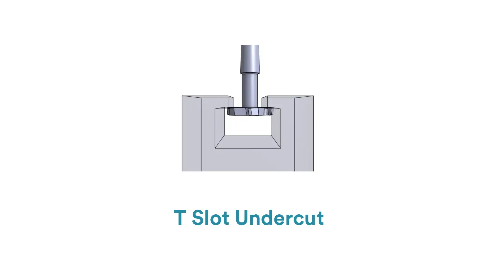
Commonly Found In:
Molds
Thread roots
Mating surfaces
O-ring grooves
Purpose: To achieve specific assembly functions, structural shapes, or aesthetic requirements.
The Essence of an Undercut: It is fundamentally a geometric shape. It specifically refers to an inwardly recessed structure that is shadowed by an overhang and requires special tools (like T-slot cutters or lollipop cutters) to be machined.
For more information about undercut, check our blog: What is Undercut in CNC Machining?
Definition: A machined groove or clearance designed to prevent interference, tool collision, or stress concentration.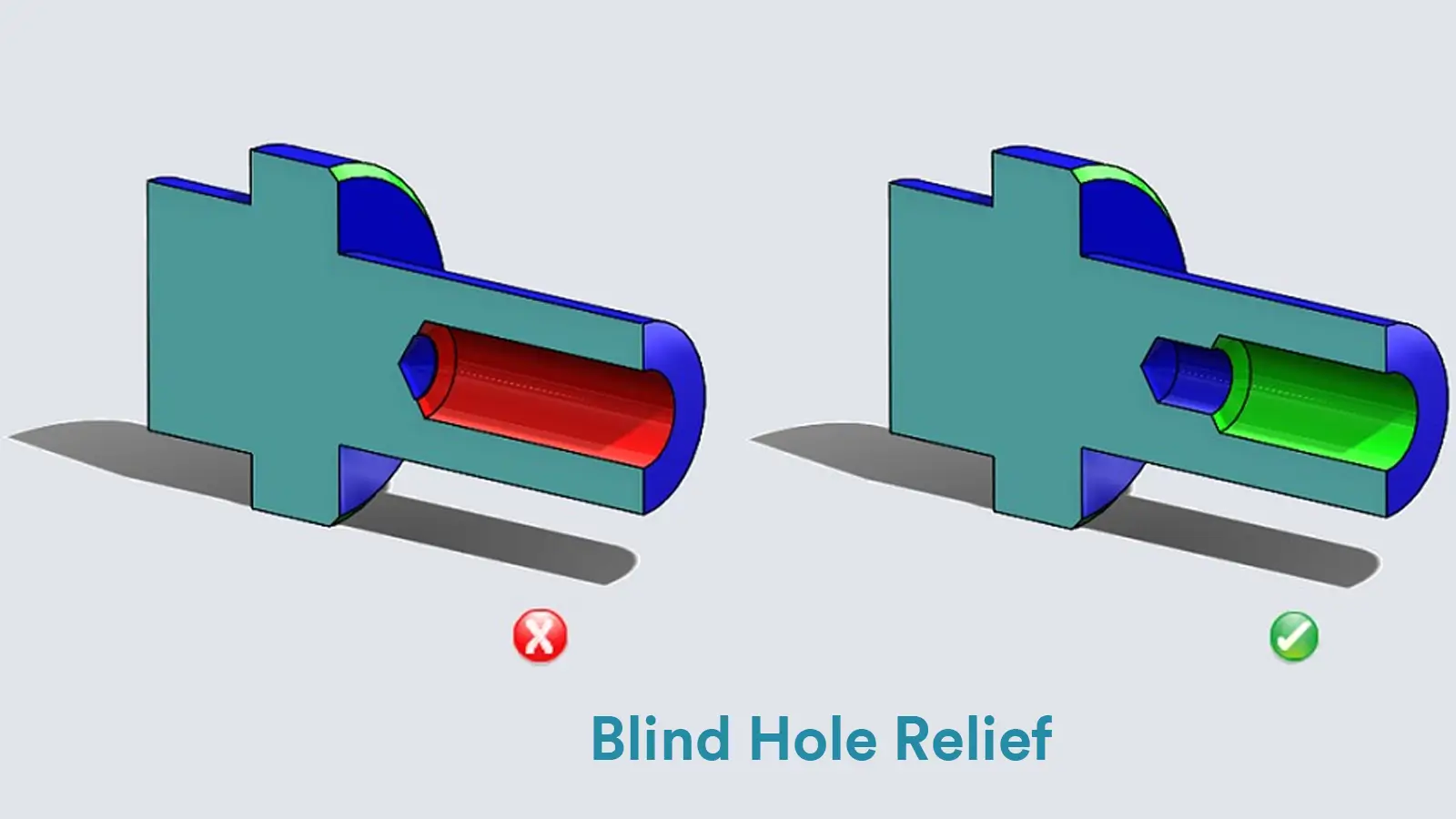
Commonly Found In:
Shaft shoulders
Thread run-outs
Hole bottoms
Purpose: To improve manufacturability, relieve stress, or aid assembly.
The Essence of a Relief: It is fundamentally a design purpose. It specifically refers to the intentional act of removing material in order to eliminate interference, distribute stress, or provide clearance.
| Comparison Item | Undercut | Relief |
|---|---|---|
| Definition | Machining an internal groove or reverse structure to enable specific assembly or demolding functions. | Removing a small amount of material at the end of a feature to avoid tool interference or facilitate tool retraction. |
| Primary Purpose | Structural or assembly requirements (e.g., snap-fits, mold release). | Machining process requirements (e.g., tool entry/exit, prevent interference). |
| Typical Location | Bottom of holes, shaft shoulders, thread limits. | End of threads, step corners, shaft ends. |
| Structural Feature | Distinct groove or reverse cut; visible. | Small groove or chamfer; auxiliary. |
| Affects Part Function? | Yes, often has a clear design function. | Generally no, only affects machining feasibility. |
| Common English Terms | Undercut groove, undercut feature. | Relief groove, thread relief, clearance cut. |
| Common Chinese Terms | 倒扣, 凹槽, 反向槽 | 避空, 退刀槽, 让刀 |
| Example Illustration | A groove below a shaft shoulder for assembly. | A groove at thread end for tool retraction. |
| Machining Tools | Ball end mills, T-slot cutters, undercut tools. | Standard turning tools or end mills. |
| Drawing Notation | “Undercut Ø…”, “Undercut to depth…” | “Thread relief p |
The reason they are frequently used interchangeably is simple: A Relief is often achieved through the geometric form of an Undercut.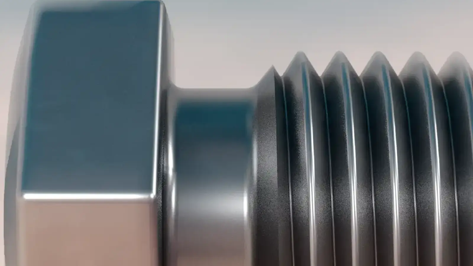
Case Study: The Thread Relief Groove
Purpose (Relief): To provide clearance for the sharp corner of a nut and allow the threading tool to exit safely.
Means (Undercut): A narrow grooving tool must be used to cut inward, creating a recessed structure—this geometry is an undercut.
Summary: In this scenario, they are two sides of the same coin. Relief is the goal, and an undercut is the necessary geometric means to achieve that goal.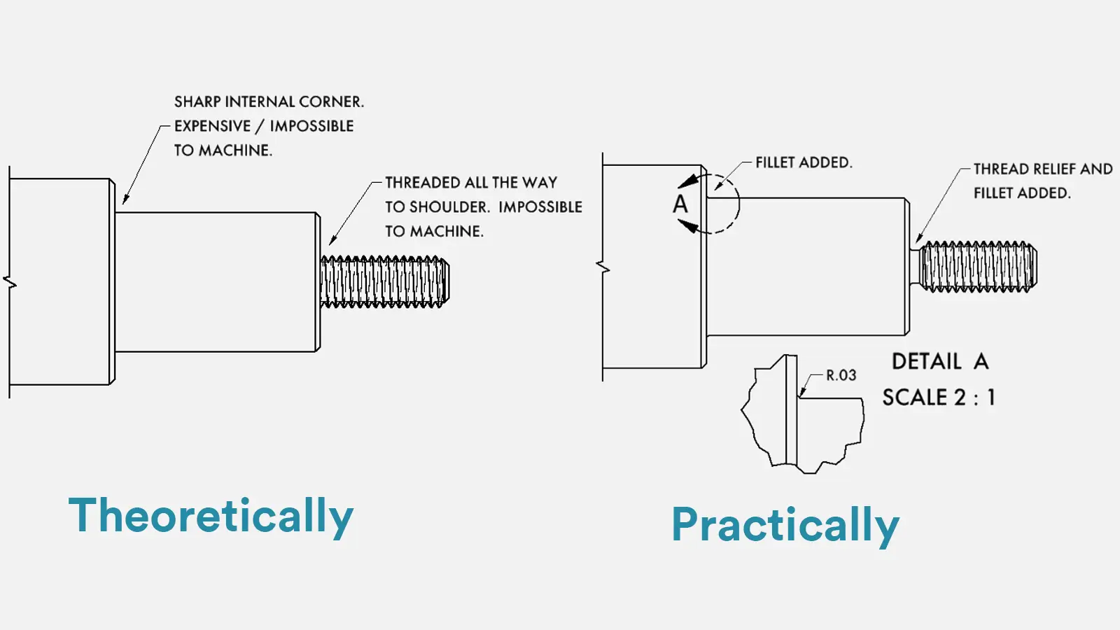
In the context of a Thread Relief Groove, the terms can be used interchangeably, but with a subtle difference in emphasis:
When emphasizing functionality (ensuring a complete thread form, avoiding interference, or binding), engineers tend to use “Thread Undercut.”
Example: “Add a thread undercut before the shoulder to ensure full thread form.”
When emphasizing manufacturability (tool runout or preventing burrs), “Thread Relief” is more common.
Example: “Provide a thread relief groove to prevent tool marks at the runout.”
In other words:
At the end of a thread, both terms refer to the same small groove. However:
“Undercut” leans more towards describing the shape of the design feature.
“Relief” leans more towards describing the machining action and its purpose.
Therefore, in practical drawings or customer communication, these two terms are often mixed, for example:
“Thread undercut per ASME Y14.6”
“Thread relief groove per ASME Y14.6”
Both formulations are standard and acceptable.
When people say “Thread Relief Groove,” they emphasize its purpose of “providing clearance and tool runout” from a machining perspective.
When they call it a “Thread Undercut,” they emphasize its role in “creating space for complete threads and proper assembly” from a functional design perspective.
Both describe the same physical feature, just with a different focus.
Definition: The primary or sole purpose of these structures is to achieve specific mechanical functions, such as connection, locking, load-bearing, or guidance, rather than to facilitate machining.
Typical Cases:
There is a distinct transverse groove at the bottom of the T-slot, which is a standard undercut structure.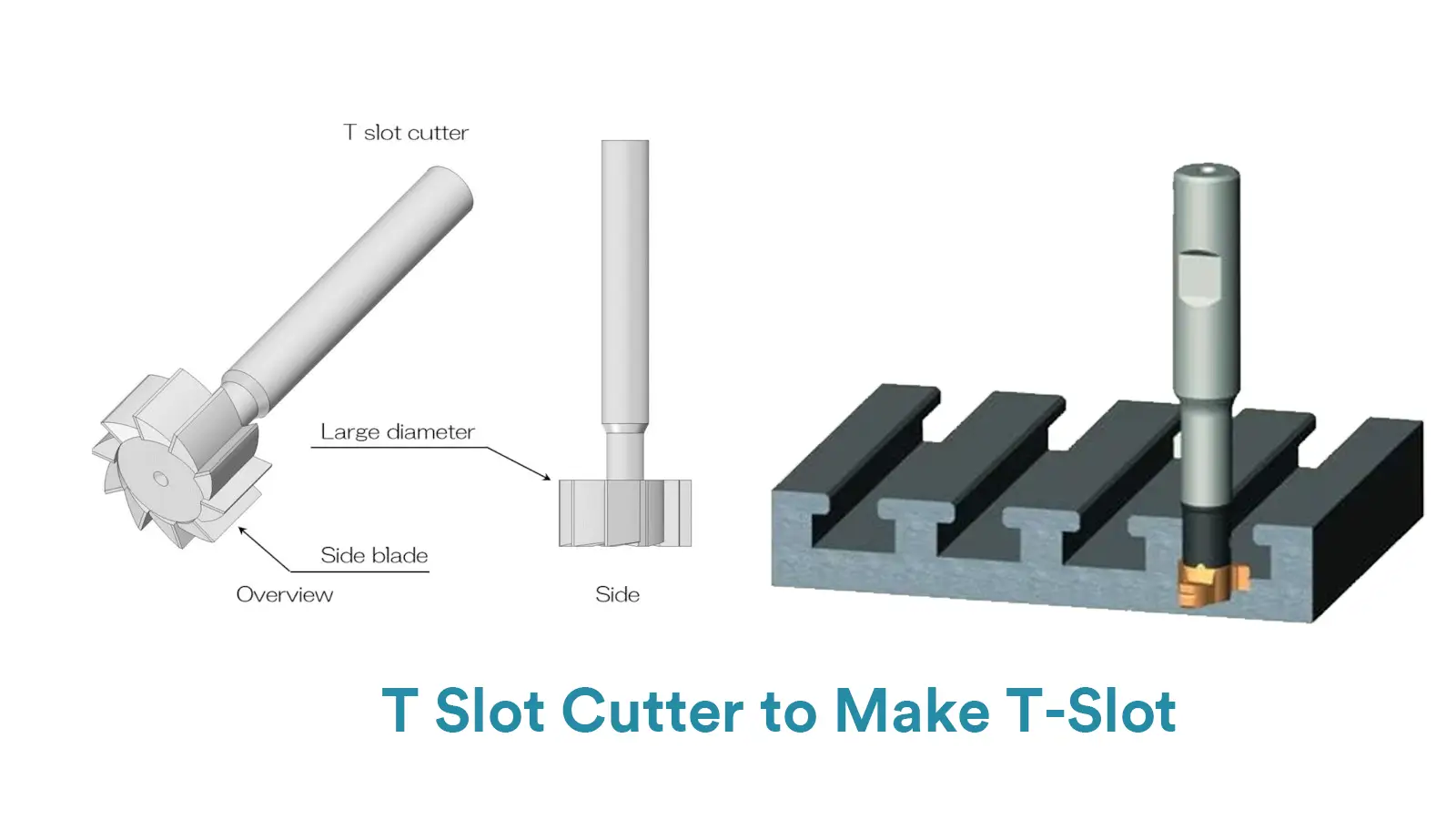
Its core function is to accommodate the head of a T-bolt, enabling the sliding and locking of components within the slot.
This groove is not intended for “tool relief” but to achieve connection and sliding functionality.
Machining it even requires specialized T-slot cutters, which itself presents a machining challenge rather than simplifying the process.
The inclined sidewalls of the dovetail slot form an interlocking structure. This is also a typical undercut.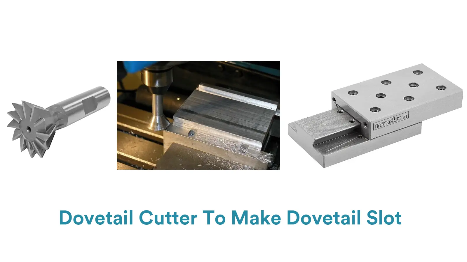
Its main purpose is to provide precise linear guidance and strong resistance to separation between two components. This undercut structure is central to its function and is unrelated to tool relief.
In plastic or metal parts, the mating area of the cantilever or hook used for a snap-fit connection constitutes an undercut.
The purpose of this undercut is to enable rapid assembly and locking. Its design is entirely dedicated to the assembly function, not the machining process.
These functional grooves or reverse structures derive their value from the product design itself; they are pure Undercuts.
The primary or sole purpose of these structures is to meet machining process requirements, such as avoiding interference, facilitating tool retraction, or relieving stress.
They themselves do not possess core mechanical functions and are typically not hidden or obstructed geometric shapes.
Typical Cases:
This example is very appropriate.
Chamfer: Removes sharp edges, prevents burrs, facilitates assembly (e.g., shaft insertion into a hole), and also serves as stress relief.
Fillet: Avoids stress concentration at internal part corners and improves fatigue strength.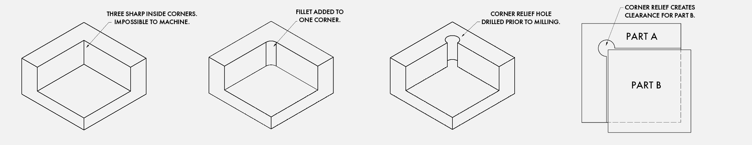
Both achieve “relief” (relieving stress concentration, avoiding assembly interference, avoiding sharp edges) by “removing material,” thus belonging to the category of Relief.
Furthermore, because they are completely open and can be machined directly from the front using standard tools, with no overhanging areas that tools cannot access, they are not Undercuts.
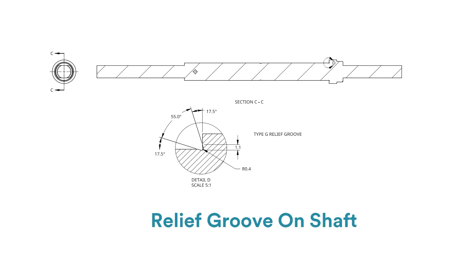
A groove is pre-machined at the end of a shaft shoulder that requires grinding.
The purpose of this groove is to allow the rotating grinding wheel to overrun the ground surface and exit safely, ensuring the root of the shoulder is fully ground.
This is a Relief structure specifically designed for the grinding process.
These are clearance structures designed for machining or safety purposes; they are pure Relief.
On engineering drawings, the callout methods for Undercut and Relief are fundamentally distinct, directly reflecting their differing design intents.
For Undercuts, the core of the callout lies in precisely defining their own geometric shape and dimensions.
As they are typically critical functional features (e.g., for snap-fits or O-ring seals), the drawing must clearly specify key parameters such as width, depth, and diameter.
Examples include direct callouts like “UNDERCUT 1.0 WIDE X 0.5 DEEP”. The focus of the annotation is to ensure the machined groove itself fully meets the design’s functional requirements.
In contrast, the logic behind Relief callouts emphasizes their process purpose and the feature they serve.
As an auxiliary machining feature, its value lies in providing space for the manufacturing of other features (such as thread turning or grinding).
Therefore, the most professional and common practice is to directly reference authoritative standards, for example, calling out “THREAD RELIEF PER ASME B1.1”.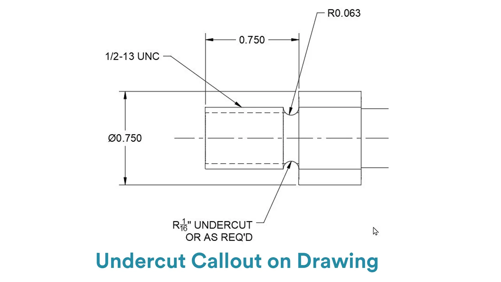
This approach is concise and unambiguous, as the standard already encompasses all necessary dimensions and form specifications.
Even when a standard isn’t referenced, the callout will explicitly indicate its purpose, such as “RELIEF FOR M10 THREAD”.
Here, the specific dimensions might be provided by the designer, but the core information conveyed is to clarify “why this groove exists and which feature it serves.”
Key Recommendations for Designers to Callout Undercut and Relief on the Engineering Drawings:
Prioritize Standardization: For Reliefs, wherever possible, reference authoritative standards like ASME, DIN, or ISO. This eliminates ambiguity and ensures compatibility with tooling and industry practices.
Clarify Functional Intent: When dimensioning an Undercut, consider adding a brief note stating its purpose (e.g., “UNDERCUT FOR SNAP RING”). This provides invaluable context for manufacturing and quality inspection personnel.
Avoid Confusion: Avoid generically labeling a groove for tool runout as an “Undercut.” This can mislead the manufacturer into treating it as a functional feature requiring special tooling.
Instead, correctly identify it based on its primary purpose: use “RELIEF GROOVE” for machining clearance and “UNDERCUT” for functional assembly features.
By employing this differentiated approach to callouts, designers can clearly and accurately communicate their design intent to the manufacturing team, thereby avoiding costly machining errors and iterative communication.
In the field of machining, Undercut and Relief are two critically important design features with distinctly different functions.
Undercuts in Mold and Die Cavities:
This is a common structure in injection or die-casting molds. To form features on the sidewalls of a product, such as textures, logos, or snap-fits, undercuts must be designed into the sidewalls of the mold cavity.
These structures prevent the mold from opening directly and require special mechanisms, such as sliders or angle-lifts, to eject the part.
Internal Grooves for O-rings:
The annular groove used to install an O-ring seal is a typical functional undercut. Its “narrow neck, wide belly” geometry provides effective sealing preload. Machining such internal grooves requires specialized grooving tools.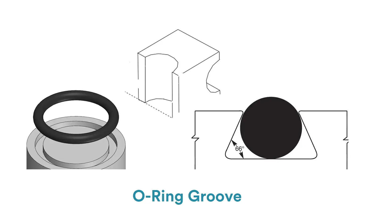
Thread Undercut:
A annular groove machined (e.g., turned) before the end of the effective thread length, but after the runout. This undercut provides a clear and sufficient escape path for the threading tool or grinding wheel, ensuring a complete and clean thread end.
Assembly or Interlocking Parts:
Components like dovetail slots, T-slots, and various snap-fit connections utilize undercut geometry to achieve precise guidance, strong locking, or rapid assembly between parts. These undercut structures are core to the product’s mechanical function.
Shaft Shoulder Relief:
An annular groove is often machined at the root of a shaft shoulder. This relief groove provides a safe overtravel space for subsequent grinding wheels or finishing turning tools, ensuring a complete square shoulder can be machined while avoiding tool wear and reducing local stress concentration.
Thread Runout Relief Groove:
This term often refers to the same feature as a “thread undercut,” but it emphasizes its functional purpose. Its core purpose is to ensure machining feasibility by providing an exit path and preventing damage to the finished threads.
Hole Bottom Relief for Tool Clearance:
A deeper hole is pre-drilled at the bottom center of a blind hole during drilling or milling.
This design aims to provide extra clearance for the drill point chisel edge or end mill tip, thereby improving chip evacuation and cooling during the cutting process, and preventing interference between the tool bottom and the workpiece, which enhances machining quality and tool life.
Stress Relief Zones:
This includes chamfers on part edges and fillets at internal corners. Chamfers facilitate assembly, prevent burrs, and relieve stress by removing sharp edges.
Fillets avoid severe stress concentration at internal corners through smooth transitions, significantly improving the part’s fatigue strength and long-term reliability.
Both are typical Relief applications that work by “removing material” to “avoid” risks.
Grinding Wheel Undercut (Relief Groove):
A groove pre-machined (e.g., by turning) at the end of a shaft shoulder that requires grinding.
The sole purpose of this groove is to allow the rotating grinding wheel to safely travel past the ground surface and exit, ensuring the shoulder root can be fully and accurately ground.
It is a Relief structure designed specifically for a particular process.
Ask yourself: Is this feature intended to install another component or to enable a specific movement? If yes, use an Undercut.
Ask yourself: Is this feature intended to allow a tool to exit cleanly or to reduce stress concentration? If yes, use a Relief.
When designing a Relief, evaluate whether an Undercut is truly necessary. If the Relief can be accomplished using standard tools, avoid designing it as an Undercut to save on manufacturing costs.
When designing an Undercut, it is crucial to specify tolerances clearly on the drawing. The precision achievable in an Undercut is often not as high as in standard milling operations due to tool access and rigidity constraints.
When you see an Undercut on a drawing: Immediately think of specialized tooling. Check the tool’s rigidity, shank diameter, neck dimensions, and overhang length to ensure it can successfully machine the feature without deflection or collision.
When you see a Relief on a drawing: Immediately think of its function. Verify that the groove’s dimensions and location are correct to ensure that subsequent assembly, tool paths, or stress distribution will function as intended. For example, verify that a thread relief groove allows a nut to run down fully.
Use standardized callouts on 2D drawings, such as “Undercut per DIN 509” or “Thread Relief per ASME Y14.6”, to ensure consistent interpretation by manufacturers.
Avoid designing excessively deep or narrow undercuts, as they may exceed the capabilities of standard tools, leading to machining difficulties or increased costs.
For complex undercut features, consider employing advanced processes like 5-axis machining or EDM to ensure accurate and efficient manufacturing.
Clearly communicate all undercut and relief requirements to the manufacturer during the quoting phase to prevent misunderstandings and additional charges later.
Another concept often confused with Relief is Clearance, which we clarify below.
When “avoidance” refers to the space that must be maintained between two entities, it corresponds to Clearance. It discusses tolerances between two mating components.
Examples:
“Tool path avoidance height” → Tool Path Clearance (safe Z-axis retraction distance)
“Sufficient avoidance is required between the bearing and housing” → Adequate Fit Clearance is needed to prevent interference during thermal expansion
When “avoidance” emphasizes eliminating interference through material removal, it corresponds to Relief. It discusses geometric feature design on components
Examples:
“A relief groove is needed here” → A Relief Groove is required to provide clearance for mating components or tools
“Shoulder relief is required” → Shoulder Relief is needed to prevent fillet interference
In practical workshop communication:
“Avoidance” functions more as a general action/concept meaning “preventing collision or interference.”
When engineers say “design an avoidance groove,” using Relief is more professional.
When engineers say “check the avoidance distance,” using Clearance is more accurate.
However, in all cases, the core objective remains creating or maintaining a safe, interference-free space.
TThese three concepts form a logical chain:
Clearance represents the purpose: ensuring interference-free space.
Relief serves as the method: intentional material removal to achieve the required Clearance.
Undercut constitutes a common form of Relief: a specific internal recessed geometry (requiring special tools) used when standard removal methods aren’t enough.
Example: Thread Relief Groove
Purpose (Clearance): Ensure clean tool exit and full seating of mating parts.
Method (Relief): Machine a groove before the thread end.
Form (Undercut): The groove is an undercut geometry because its bottom diameter is smaller than the external surface, blocking access from a vertical tool.
Both Undercut and Relief are common geometric features in CNC-machined parts. Undercut is typically driven by specific functional requirements, while Relief primarily serves manufacturing feasibility and efficiency.
In short, an undercut is a geometric recess that requires special tooling, while a relief is a clearance feature designed for machining or stress reduction.
In thread runouts, the distinction between these terms can be blurred and sometimes interchangeable. However, in most other applications, they have clear differences in design intent and geometric characteristics.
A deep understanding of their differences enables engineers to achieve more rational product designs, more efficient manufacturing processes, and better-controlled project costs.
| Concept | Core Definition (in CNC) | Primary Purpose | Common Applications |
|---|---|---|---|
| Clearance | The physical space left between two parts or part features to avoid interference. | Prevent interference/collision: Ensure adjacent parts or tools do not contact each other during movement, assembly, or function. | Bearing and shaft shoulder, Thread end and vertical face, Tool and workpiece. |
| Undercut | A recessed feature on a part where the machining area cannot be accessed directly from above by a standard vertical tool (often requiring special tools). | Create complex geometries; Serves as a form of Relief groove. | T-slots, Dovetail slots, Grooves at thread ends, Internal recesses in parts. |
| Relief | The removal of material in a specific area of a part to achieve a design purpose, especially at corners, steps, or thread ends. | a) Provide Clearance: Facilitate tool retraction or ensure assembly.b) Reduce stress concentration. | Thread Relief grooves, Shaft shoulder relief, Mold release features. |
An undercut is a recessed area that cannot be directly machined with standard tools—it usually requires special cutters such as T-slot, dovetail, or lollipop cutters.
A relief, on the other hand, is a small groove or clearance intentionally machined to prevent interference, release stress, or allow tool exit.
Simply put: Undercut = geometric feature, Relief = design purpose.
Because both involve removing material.
In fact, a relief can sometimes take the form of an undercut.
Example: The groove at the end of a thread can be called a thread relief (focus on purpose) or a thread undercut (focus on shape)—both describe the same feature from different viewpoints.
Use undercuts when your part needs a specific function, such as:
Fitting O-rings for sealing
Creating locking or sliding features (T-slots, dovetails)
Providing clearance for full thread engagement near a shoulder
Keep in mind that undercuts usually require special tools and may increase machining cost.
Choose a relief when your goal is machining efficiency or stress reduction, for example:
Allowing a tool to exit cleanly at the end of a thread
Reducing stress concentration at a corner
Avoiding interference between a shoulder and mating part
Reliefs are simpler to machine and are generally cost-effective.
Yes — but differently.
Undercuts may require special tools or 5-axis setups, increasing cost and lead time.
Reliefs are usually made with standard tools and often reduce machining time.
Tip: Always discuss with your machinist before finalizing the design to find the most efficient option.
Absolutely.
Use clear and recognized standards such as:
ASME Y14.6 for thread reliefs
DIN 509 for undercuts
This ensures manufacturers interpret your design correctly, avoids rework, and simplifies quality inspection.
Because they describe the same physical feature from different angles.
“Undercut” focuses on geometry and form.
“Relief” focuses on machining purpose and function.
It’s perfectly normal for both to appear together, especially in detailed 2D drawings following ASME or ISO standards.
Be explicit and visual.
Include clear callouts: e.g., “Thread relief per ASME Y14.6” or “Undercut for O-ring seal”.
Add a brief note explaining its purpose — this helps avoid misunderstanding and extra cost.
Most CNC shops appreciate when designers clearly indicate why a groove exists, not just its dimensions.
You’ve hit on a key point! This is a classic case where the two concepts overlap:
From a purpose perspective: It’s a Relief, because it provides an exit path for the threading tool and prevents damage to the threads.
From a form perspective: It’s an Undercut, because it is an inwardly recessed annular groove.
Communication advice:
When discussing function with your manufacturer (e.g., “ensuring the nut can be fully tightened”), call it a Thread Relief.
When discussing machining and dimensions (e.g., “the width and depth of this groove”), you can refer to it as a Thread Undercut.
The safest approach: Label it on the drawing as a “Thread Relief Groove” and reference a standard (e.g., “Per ASME B1.1”). This makes the intent clearest.
This is because they are typically critical functional features. For example, the dimensions and tolerances of an o-ring groove must be extremely precise to guarantee a reliable seal. The stricter the tolerances, the longer the manufacturing and inspection time, and consequently, the higher the cost will be.
Complex Undercuts require multi-axis programming and the customization or procurement of specialized cutting tools. Furthermore, the machining process itself is prone to tool vibration and difficult chip evacuation. This can lead to a higher scrap rate or demand more time for test cuts and adjustments, thereby extending the overall lead time.

Undercut is a “Hidden” Geometry: It’s a recessed feature inaccessible by standard vertical tools, demanding specialized cutters (T-slot, lollipop) or multi-axis movement.

China is the best country for CNC machining service considering cost, precision, logistic and other factors. Statistical data suggests that China emerges as the premier destination for CNC machining.

Selecting the right prototype manufacturing supplier in China is a critical decision that can significantly impact the success of your product development project.

Machining tolerances stand for the precision of manufacturing processes and products. The lower the values of machining tolerances are, the higher the accuracy level would be.