We recently worked on a series of overseas mechanical equipment projects in which both CNC-machined components and sheet-metal parts required welding.
The CNC parts were made from A36 steel and required welding followed by powder coating. The sheet metal parts were 304 stainless steel, which required post-weld grinding to achieve a smooth, burr-free finish.
This is a great opportunity to walk through the main welding processes — useful for anyone in CNC, sheet metal fabrication, or mechanical engineering.
Although welding may look complex at first, it can actually be categorized into three main types: fusion welding, pressure welding, and brazing. The key difference between them is whether the base metal is melted during the process.
Here’s a simple way to think about them:
Fusion welding: like melting the ends of two candles and letting them fuse together as they cool.
Pressure welding: like kneading dough—heat and strong pressure “blend” two metal pieces into one solid body.
Brazing: like using glue—only the filler material melts, while the base metals remain solid.
This is the most common welding type. The core principle is melting both the base material and the filler wire, then forming a weld seam after cooling.
TIG welding is the preferred process for thin sheets and precision components. It uses a tungsten electrode with argon shielding gas, producing a very clean, precise, and spatter-free weld.
In sheet metal enclosures and stainless steel housings, TIG is often used for all visible weld seams.
Key advantages:
Limitation:
MIG welding is a high-efficiency, production-oriented process. It uses a wire feeding system for continuous welding, making it several times faster than TIG welding.
It is commonly used for CNC machine guards, heavy steel frames, and robotic welding systems.
Key advantages:
Typical applications:
MIG welds are generally not as fine as TIG welds and may produce more spatter, which often requires post-grinding. For high cosmetic requirements, TIG is still preferred.
Laser welding is a high-precision, low-deformation “advanced” welding technology. It uses a high-energy laser beam to instantly melt the material with minimal heat-affected zone.
Key advantages:
It is widely used in high-end precision enclosures, CNC structural parts with tight tolerances, and sealing applications where deformation must be minimized.
Stick welding is a flexible and robust method commonly used for outdoor fabrication and heavy steel structures.
It is often used for machine bases, structural frames, and on-site repair work.
Advantages:
Disadvantages:
It is rarely used in precision CNC or sheet metal manufacturing.
Pressure Welding does not use filler material. Instead, it joins metals at the atomic level — no filler material needed — resulting in excellent joint strength.
Spot Welding is also know as Resistance Welding. It is the most efficient method for sheet metal overlap joints. It uses electrical resistance heat generated at the contact point, combined with pressure, to form a weld.
It is widely used in sheet metal enclosures and cabinet assemblies.
Key advantages:
Limitations:
Typical applications:
Friction Stir Welding is a solid-state joining process that uses a rotating tool to generate frictional heat, softening the material without melting it, and then forging it together.
It is widely used in high-performance applications such as:
Although cost is relatively high, the joint strength and reliability are extremely excellent.
Brazing is more like “metal adhesive bonding.” The base materials do not melt; only the filler metal melts and flows into the joint.
It is mainly used for joining dissimilar metals or precision tubing systems.
Typical applications include:
Brazed joints usually have good appearance, but the strength is lower than true fusion welding.
We once worked with a U.S. customer on a brazed assembly project. However, due to the lack of a suitable local supplier, we manufactured the parts and shipped them to the United States, where the brazing process was completed by the customer on their side.
In precision sheet metal fabrication, welding is one of the main methods for forming and joining parts. From a flat sheet to a finished product — like an enclosure, control cabinet, or equipment housing — welding plays a key role throughout the process.
Examples include electrical cabinets, telecom enclosures, and medical device covers. After bending, welding is used to join panels, internal stiffeners, and mounting brackets into a rigid structure.
In these cases, TIG welding (either spot or continuous) is the most common choice — it offers clean welds with minimal distortion.
Think high-end instrument housings or lab equipment enclosures. To avoid visible weld marks or surface damage, manufacturers typically use laser welding or precision TIG welding — sometimes with the requirement that the weld be completely invisible after finishing.
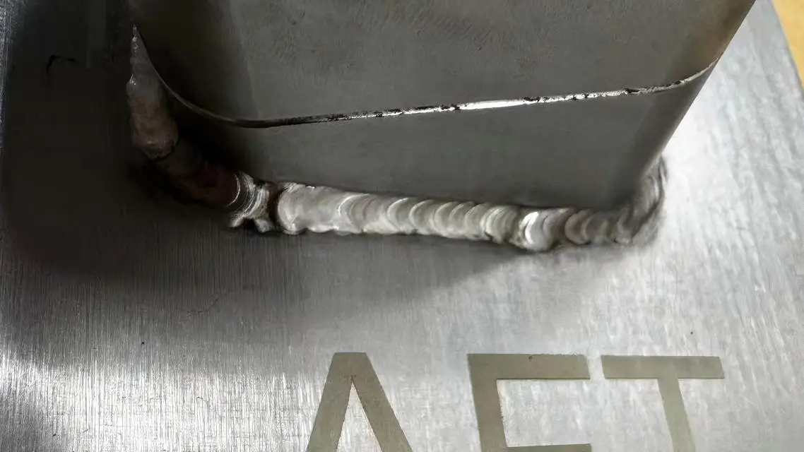
Even when the main body is made from formed sheet metal, load-bearing areas — such as equipment bases or support frames — often require MIG welding for stronger, more reliable joints.
Based on our hands-on experience in sheet metal welding — especially for precision work — TIG welding accounts for about 60–80% of total welding effort.
Let me explain why.
Precision sheet metal frequently uses stainless steel, cold-rolled steel, and aluminum in thicknesses ranging from 0.5mm to 3mm.
TIG offers the best control for thin materials, producing:
That makes TIG ideal for appearance-critical parts like enclosures, cabinet doors, and equipment housings.
Plus, TIG is highly flexible — you can use it for tack welding to hold parts in place, or run continuous beads for full-strength joints.
In sheet metal fabrication, spot welding is used primarily for lap joints — for example, attaching internal stiffeners or securing double-layer sheets. It’s fast and creates little to no distortion, but it’s not suitable for sealed seams or visible surfaces.
Laser welding is reserved for ultra-high-appearance requirements or very thin materials where heat distortion is a major concern. Currently, we outsource our laser welding to specialized partners.
Strictly speaking, traditional CNC machining doesn’t require welding. However, in the broader context of CNC-manufactured parts and assemblies, welding comes up frequently — especially in custom automation and specialty equipment.
Here are the three most common scenarios:
Think of a precision-machined locating block, adapter plate, or mounting bracket that needs to be welded onto a sheet metal enclosure or a machine base. In this case, welding becomes part of the assembly process — and it’s very common in automation equipment and custom machinery.
Some components start as multiple pieces that are first welded into a rough blank — for example, a welded steel structure or a machine frame — and then machined on a CNC for final dimensional accuracy.
Typical examples include:
Welded machine bases (ribbed plates + steel sheets, welded first, then machined on mounting surfaces)
Robotic arm structural components
This is a “weld + CNC” hybrid process — welding comes first, followed by precision machining.
If a casting or welded part has a localized defect (like porosity or missing material) discovered during CNC machining, welding may be used to repair it. After welding, the part goes back on the CNC for a finishing pass. This happens occasionally — usually on low-volume or high-value parts.
Based our NC manufacturing experience .TIG is the go-to welding process for precision CNC components — especially for aluminum and stainless steel structural parts, because TIG offers controllable heat input, high weld quality and minimal distortion.
Laser Welding is used less frequently, but it’s the right choice for ultra-precision CNC applications, thin-walled components and parts where low distortion and high consistency are critical.
MIG Welding & Spot Welding is not common in Precision CNC Parts.
Not all materials are easy to weld — and in sheet metal and CNC parts manufacturing, the differences in weldability are significant.
The most common and reliably weldable materials are carbon steel, stainless steel, and aluminum. Here’s what you need to know about each.
Carbon steel is one of the most weldable materials available. It works well with MIG, TIG, and spot welding — offering high joint strength and a wide process window.
That’s why carbon steel is widely used in structural parts and industrial equipment. It’s forgiving, predictable, and cost-effective.
Stainless steel — especially 304 and 316 — is very common in both sheet metal and CNC components.
To maintain a clean, attractive weld and avoid excessive oxidation or discoloration, TIG or laser welding is typically used.
The biggest challenge with stainless steel is Distortion. Controlling heat input is critical to keep parts flat and within tolerance.
Aluminum alloys like 6061, 5052, and 6063 are widely used in CNC machining, but welding aluminum is more demanding than steel.
Aluminum is typically welded using TIG or MIG, but it requires tight process control and experienced welders.
There are the two main issues with aluminum welding: Porosity and Distortion.
Some specialty materials — such as galvanized steel, copper alloys, or high-alloy steels — can also be welded. However, they typically require more stringent process controls and sometimes even specialized welding methods.
| Material | Weldability | Common Issues | Recommended Processes |
|---|---|---|---|
| Carbon Steel | ✅ Excellent | Very few | MIG, TIG, Spot |
| Stainless Steel (304/316) | ⚠️ Good | Distortion, oxidation | TIG, Laser |
| Aluminum (6061, 5052, 6063) | ⚠️ Moderate | Porosity, distortion | TIG, MIG |
| Free-machining steel (e.g., 12L14) | ❌ Poor | Cracking, weak joints | Not recommended |
| Copper alloys | ⚠️ Difficult | Heat control | Specialized methods only |
In summary, carbon steel is the easiest to weld. Stainless steel and aluminum can be welded successfully — but they come with important caveats. Free-machining steels and copper alloys are generally not recommended for welding in precision applications.
After welding is complete, the weld area — and often the entire part — typically requires surface finishing. There are three main reasons for this:
Clean the surface – Remove contaminants and oxidation
Improve appearance – Achieve a consistent, professional look
Enhance corrosion resistance – Extend part life
Surface finishing is a critical step that directly affects both the visual quality and the long-term durability of welded components.
Anodizing is the most common finish for aluminum. However, the weld area and base material often react differently during anodizing, which can result in color variation.To avoid this issue, in our workshop, we do final machining after welding, and grind or sand the weld area before anodizing.
For stainless steel weldments, the most common surface finishing methods include Brushed finish, Polished finish and Passivation. These processes can improve surface uniformity and restore corrosion resistance after welding.
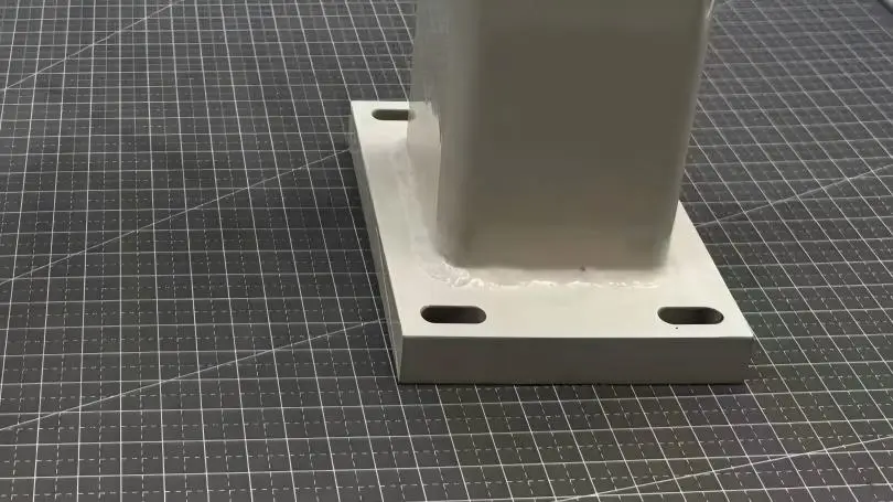
Carbon steel is strong and weldable, but it rusts easily without protection. That’s why welded carbon steel parts requires Powder coating or Spray painting, which can provide rust protection and significantly improve the final appearance.
Below a A36 parts with powder coating surface treatment.
Welding defects are one of the most critical quality issues in manufacturing. Even a small defect can affect part fit, assembly, or long-term reliability.
The most common welding defects list is as below:
Let’s break them down — and explain what we do to prevent them.
These defects can’t be seen with the naked eye, but they can compromise structural integrity.
| Defect | What It Is | Common Causes |
|---|---|---|
| Porosity | Small gas pockets trapped in the weld | Contaminated material surface, unstable shielding gas — especially common in aluminum welding |
| Cracking | Cracks in the weld or heat-affected zone | High stress, wrong filler material, or cooling too quickly |
| Lack of fusion / incomplete penetration | Weld looks complete but isn’t fully bonded | Low current, travel speed too fast, improper joint preparation |
These defects affect appearance and may require rework — but they don’t always compromise strength.
| Defect | What It Is | Common Causes |
|---|---|---|
| Undercut | A groove melted along the edge of the weld | Current too high, incorrect torch angle |
| Excessive weld bead (overfill) | A large, bulging weld sitting on top of the joint | Current too high, travel speed too slow |
| Slag inclusions | Dark spots or debris on the weld surface | Improper cleaning between passes |
| Uneven weld bead | Wide-narrow-wavy weld appearance | Unsteady hand, uneven travel speed |
| Spatter | Small metal beads around the weld area | Mismatched voltage/current settings (common in MIG) |
Welding almost always causes some level of distortion — angular distortion, warping, twisting, or buckling. The main cause is uneven heat input or insufficient fixturing.
Distortion during welding is unavoidable, but it can be effectively controlled. At ECOREPRAP, through proper process design, fixturing, and heat management, deformation in many sheet metal assemblies can typically be maintained within ±0.5 mm.
Overall, among the three major welding defects—surface defects, internal defects, and dimensional defects—internal defects are the most dangerous because they are not visible externally but directly affect structural safety.
The core of improving welding quality is making the welding process more stable, controllable, and consistent.
In precision sheet metal fabrication and CNC manufacturing, high welding quality does not rely on a single factor. It is the result of proper product design, process selection, material preparation, fixture control, and standardized production management working together.
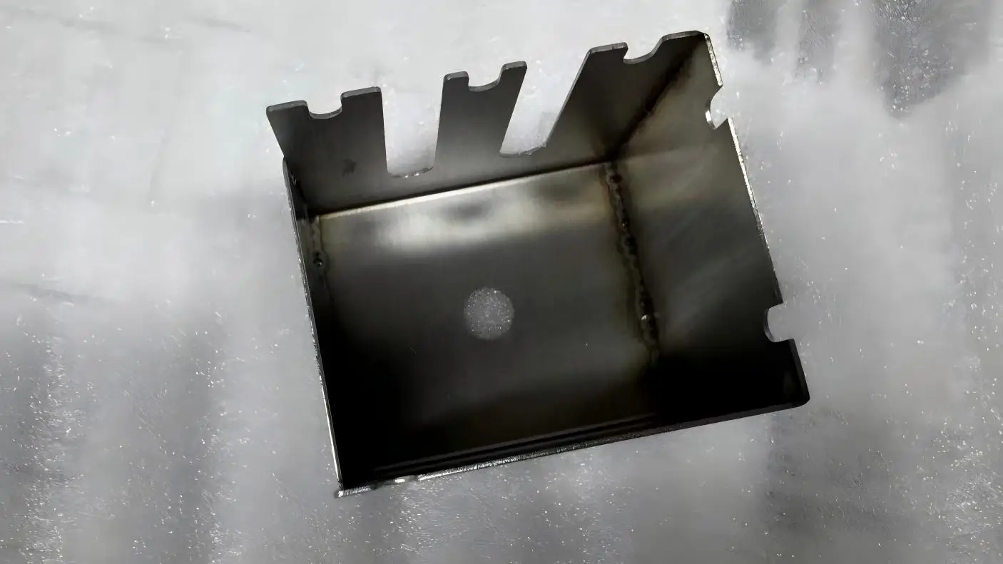
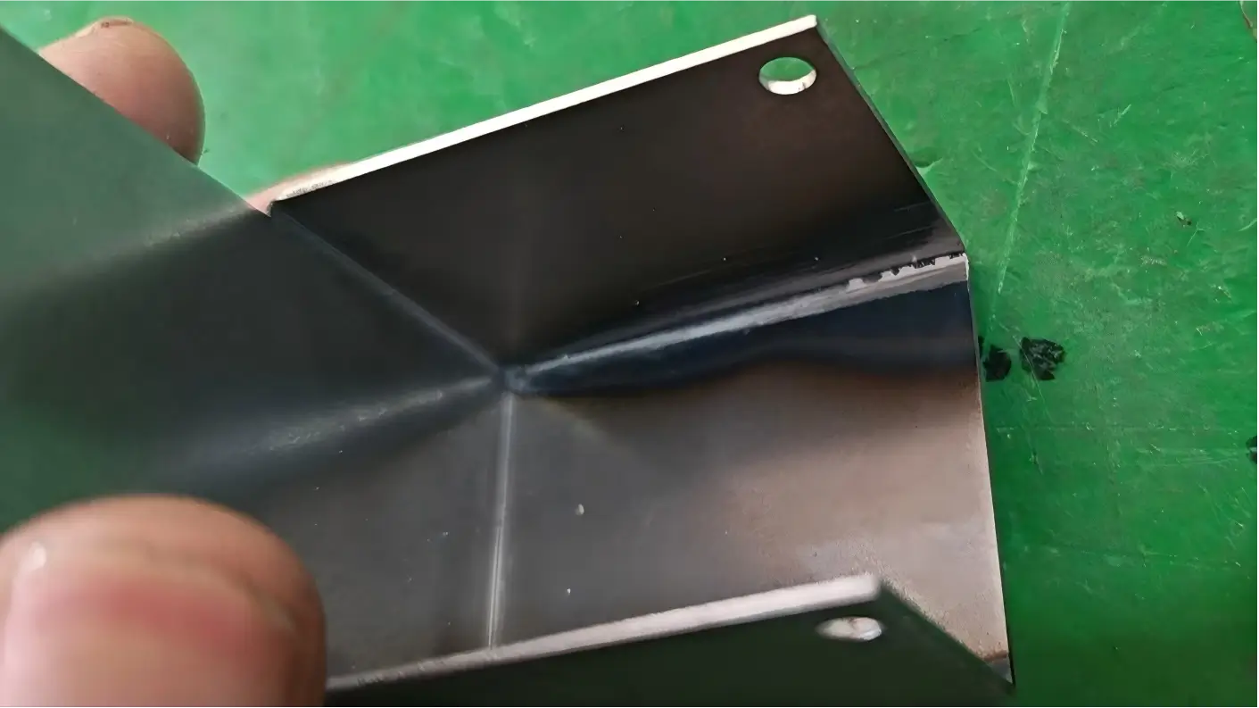
Below shows a sheet metal weld part.
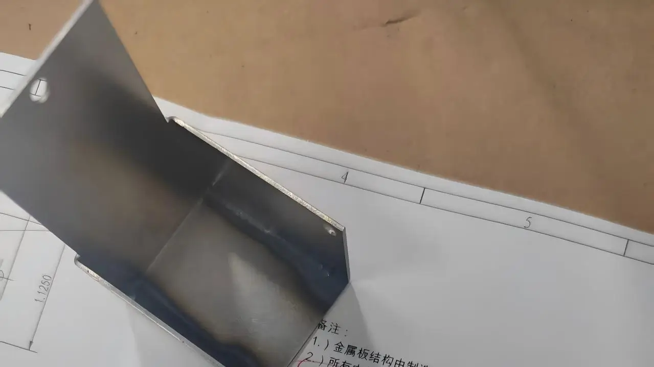
The weld part is polished.
One of the most effective ways to improve welding quality starts before production even begins—during the product design stage.
Good welding-friendly design can significantly reduce:
Based on our manufacturing experience, there are several important design considerations.
Sharp corners and tightly concentrated weld areas tend to create stress concentration points. These areas are more likely to crack during welding, deform after cooling and fail during long-term use.
Reducing unnecessary weld density also helps minimize heat accumulation and distortion.
Proper weld groove preparation helps ensure better welding torch accessibility, more consistent weld penetration, and stronger joint bonding. This is especially important for thicker materials, where good joint design allows the welding process to remain stable and controlled, ultimately improving weld strength, reliability, and overall structural performance.
Engineering drawings should clearly indicate critical weld seams and standard weld seams.
This allows the welding and inspection teams to apply different quality control standards depending on the application.
For example, critical structural welds may require tighter process control and non-destructive testing, while standard welds can follow normal production standards.
Weld shrinkage is a predictable and well-understood physical behavior in welding processes. When the structure is designed symmetrically, the shrinkage forces on both sides can naturally counterbalance each other, which significantly helps reduce welding distortion, twisting, and overall dimensional movement. This design approach is especially critical for large sheet metal assemblies, precision enclosures, and welded CNC structures where dimensional stability and tight tolerances are required.
At ECOREPRAP, we review customer drawings early in the development stage and provide manufacturability feedback before production begins. During this process, we may identify potential welding-related issues such as excessive weld density, missing weld grooves, poor structural symmetry, or areas with limited welding accessibility.
Secondly, selecting the appropriate welding process is critical. For high-precision components, TIG welding or laser welding is typically preferred over traditional high heat-input welding methods, as they provide better control and reduced thermal distortion.
Thirdly, surface cleanliness of the material has a direct impact on weld quality. This is especially important for aluminum alloys, where any oil, oxide layer, or contamination can easily lead to porosity or unstable weld seams.
Fourth, fixture design plays a key role in controlling deformation. Proper fixturing and workpiece restraint can significantly reduce welding-induced thermal distortion and improve dimensional consistency.
Fifth, welding parameter control—including current, voltage, travel speed, and shielding gas—must be fully standardized. Without consistent parameters, quality variations between production batches can become significant.
Finally, in many high-end manufacturing applications, secondary CNC machining or surface finishing is performed after welding to ensure final dimensions and surface appearance meet precision standards.
You are welcome to send us the drawings for any welded part you need.
Carbon steel is generally the easiest material to weld, followed by stainless steel such as 304 and 316.
Aluminum alloys are the most challenging because they require stricter process control and more experienced welders. Aluminum welding is more prone to porosity, oxidation, and distortion, which places higher demands on fabrication capability and welding expertise.
Welding distortion is mainly caused by uneven heat input.
When a localized area is heated to a high temperature, the material expands, and during cooling, uneven shrinkage can lead to warping or dimensional deviation.
In precision manufacturing, deformation is usually minimized through fixture design, optimized welding sequences, and careful heat input control.
The key to preventing welding defects is proper process control. This includes material cleaning, stable shielding gas protection, appropriate welding parameters, and standardized welding procedures. High-quality fixtures and tooling also help reduce issues such as porosity, cracking, and distortion.
Yes, but dimensional control must be considered during both the design and manufacturing stages. This is typically achieved through optimized welding sequences, fixture positioning, and post-weld CNC machining.
For high-precision applications, a “welding + secondary machining” process is commonly used to ensure critical dimensions.
Metal Inert Gas welding (MIG welding), also known as Gas Metal Arc Welding (GMAW), is a welding process that uses a continuously fed wire electrode and shielding gas to create the weld.
MIG welding is fast, efficient, and widely used for carbon steel, stainless steel, and thicker fabrication parts. It is especially suitable for high-volume production and structural welding.
Tungsten Inert Gas welding (TIG welding), also known as Gas Tungsten Arc Welding (GTAW), uses a non-consumable tungsten electrode to produce the weld.
TIG welding provides excellent precision, clean weld appearance, and superior control, making it ideal for thin-wall components, aluminum parts, stainless steel products, and cosmetic welds in CNC and precision sheet metal fabrication.
MIG welding offers higher efficiency and is better suited for thicker materials and mass production. However, the weld bead is generally rougher and produces more spatter.
TIG welding is slower but far more precise, producing cleaner and more aesthetically pleasing welds. For this reason, TIG welding is commonly preferred in CNC machining and precision sheet metal fabrication, especially for appearance-critical or thin-wall components.
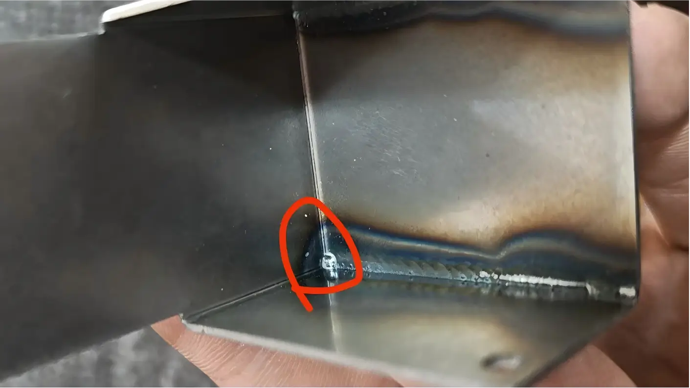
Yes, this is normal. During stainless steel welding, high temperatures create oxidation colors in the heat-affected zone, ranging from gold to blue and dark blue depending on the temperature. These oxide layers not only affect appearance but can also reduce the corrosion resistance of stainless steel.
To restore corrosion resistance and the original silver-white appearance, stainless steel welds are typically treated with pickling and passivation after welding. If a completely seamless cosmetic appearance is required, additional grinding or polishing can also be performed.
Yes, aluminum welding is generally more challenging than stainless steel welding.
Aluminum naturally forms a dense oxide layer whose melting point is much higher than aluminum itself. If not properly removed before welding, it can cause inclusions and porosity.
In addition, aluminum conducts heat very quickly, requiring higher heat input while also increasing the risk of burn-through and distortion.
To ensure high-quality aluminum welds, we typically:
With the correct process, aluminum welds can still achieve excellent strength and appearance. For applications requiring extremely high strength or airtightness, we may also recommend laser welding or friction stir welding.
Our typical approach is to use either a “weld-then-machine” or “post-weld straightening + finish machining” strategy.
For welded frames, bases, and structural components, all welding is completed first, followed by stress-relief heat treatment to eliminate internal stress. Critical features such as mounting surfaces and locating holes are then CNC machined afterward to ensure final precision.
For thin sheet metal parts, we may use laser welding or spot welding to reduce heat input, or incorporate locating features into the design to assist with post-weld alignment correction. In general, critical tolerances are best achieved through post-weld machining rather than relying on welding alone to maintain dimensional stability.
For precision sheet metal fabrication, we can reliably weld materials as thin as 0.5 mm using TIG welding or laser welding, especially for stainless steel and carbon steel. For materials thinner than 0.5 mm, processes such as spot welding, laser welding, adhesive bonding, or mechanical joining are often recommended instead of traditional fusion welding.
For thicker structural components, carbon steel plates between 5 mm and 30 mm are commonly welded using MIG welding with multi-pass techniques to achieve full penetration. For thicknesses above 30 mm, bevel preparation and even submerged arc welding may be required.
Our standard welding capability range is approximately 0.5 mm to 30 mm, while thicker or thinner applications require case-by-case evaluation.

5-Axis CNC machining is a manufacturing process that uses computer numerical control systems to operate 5-axis CNC machines capable of moving a cutting tool or a workpiece along five distinct axes simultaneously.

China is the best country for CNC machining service considering cost, precision, logistic and other factors. Statistical data suggests that China emerges as the premier destination for CNC machining.

Selecting the right prototype manufacturing supplier in China is a critical decision that can significantly impact the success of your product development project.

Machining tolerances stand for the precision of manufacturing processes and products. The lower the values of machining tolerances are, the higher the accuracy level would be.


