CNC chatter is a self-excited vibration that occurs when cutting forces interact with machine-tool dynamics. It is a high-pitched and self-excited CNC vibration or resonant oscillation happening between the cutting tool and workpiece during processing.
CNC chatter tends to create a resonant feedback loop that produces loud noise, uneven surface marks, and even tool or machine damage. It is important for CNC operators to know what causes CNC chatter and how to avoid this problem.
This article will provide a detailed guide of CNC chatter, including what it is, how does it look like, what causes CNC chatter, and how to solve it.
Key Takeaways:
CNC chatter is an undesirable and high-pitched vibration between the cutting tool and the part being machined. It typically occurs when the cutting tool and workpiece interact in a way that creates rapid and uncontrolled oscillations.
It does not simply an annoying noise, but means that the machining process loses its stability of settings. When CNC machine chatter happens, the tool begins to bounce or rub against the machining component instead of shearing the material smoothly.
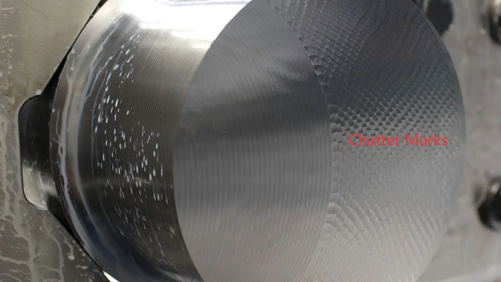
Below is one 5 axis CNC machining part we made but it is not a good one, because it has a chatter issue.
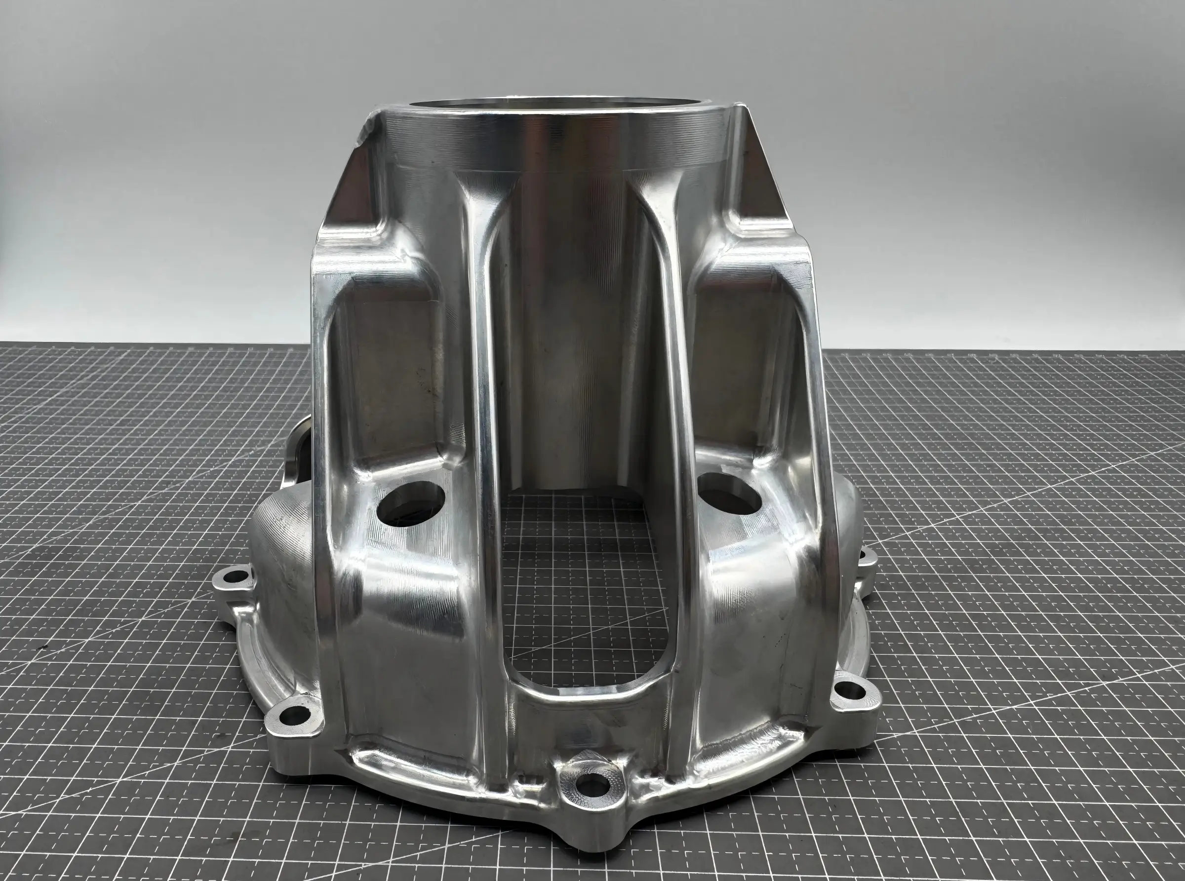
Photo of chatter is shown below.
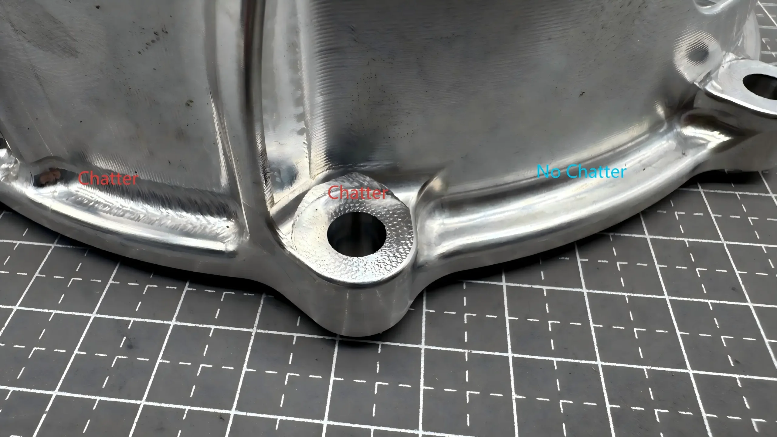
This would then leave behind a rough surface finish with uneven wavy chatter marks, accelerate tool wear, and even damage spindles or workholding over time.
And such a CNC vibration can typically be classified into resonant chatter and non-resonant chatter.
Resonant chatter occurs when the operating frequency of the whole settings of the CNC machine matches or is extremely close to its natural frequency. It often happens at certain position within the machine like the pocket corner.
While non-resonant chatter is commonly lead by unevenly worn tool, imbalanced cutting forces or other mechanical causes. This type of vibration will typically be constant throughout the whole CNC machining process.
Unlike minor tool marks or feed lines, chatter marks have distinct, repetitive patterns that signal a problem with the machining setup. And the chatter marks in milling, turning, and drilling are certainly different.
The most defining feature of chatter marks is a series of evenly spaced and wave-like ridges or ripples on the machined surface. These waves are consistent in spacing and shape, unlike random scratches or uneven tool marks.
Unlike feed lines or random scratches, chatter marks themselves keep a uniform distance between each wave. This spacing is determined by the frequency of the vibration. Chatter under higher frequency creates tighter and closer waves, while that under lower frequency results in wider and more spread-out ripples.
In most cases, chatter marks run perpendicular or at a sharp angle to the direction the tool is moving. For example, in CNC milling, if the tool is moving along the X-axis, the chatter marks will run along the Y-axis. This is because the vibration occurs between the tool and workpiece, acting against the direction of cut.
CNC machining chatter marks are often visible to the naked eye. They can also be felt by running finger over the surface. These marks are rough, bumpy, or ridged, even on surfaces that should be smooth. In severe cases, the ridges can be deep enough to catch a fingernail.
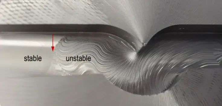
Chatter usually occurs during the milling process, especially when the tools are long, the parts are thin-walled, or the materials are highly rigid.
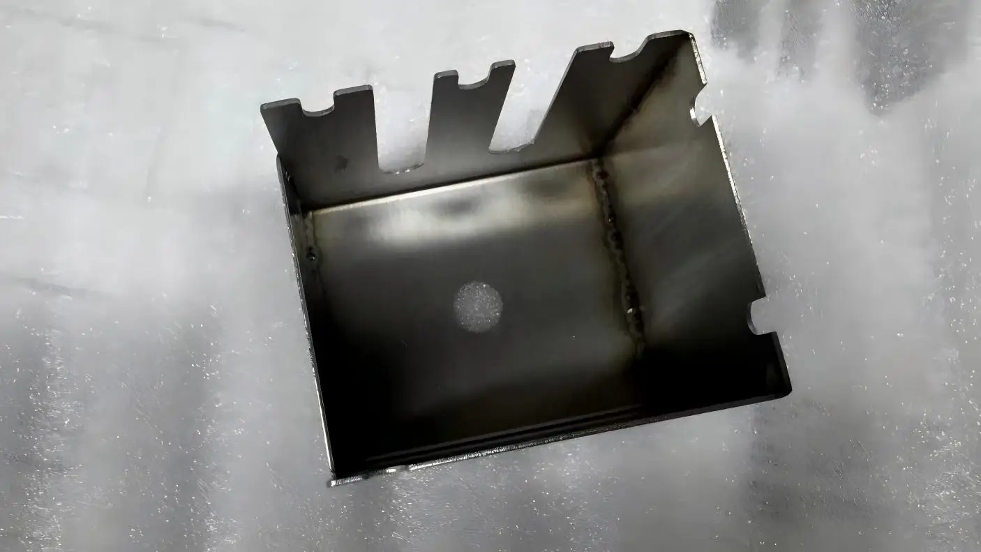
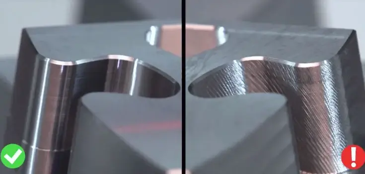
Vibration marks created during milling appear as wavy or scalloped ridges on flat surfaces in face milling or along the sides of slots in end milling.
The right photo below shows the milling chatters while the left is the good milling performance.
On 3D surfacing, chatter marks may look like uneven ripples that disrupt the smooth contour of the part.
And if a ball-end mill is used, chatter marks would appear as irregular and repetitive grooves that follow the tool’s path but with a wavy distortion.
Distinct chatter marks might appear during turning process due to part flexing, especially on slender shafts or thin-walled parts.
The chatter marks in turning example is shown below.
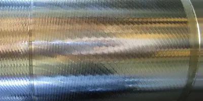
Chatter marks created during the CNC turning process often run parallel to the axis of the component since the tool is stationary while the part rotates.
Below is the chatter marks during external and groove turning.
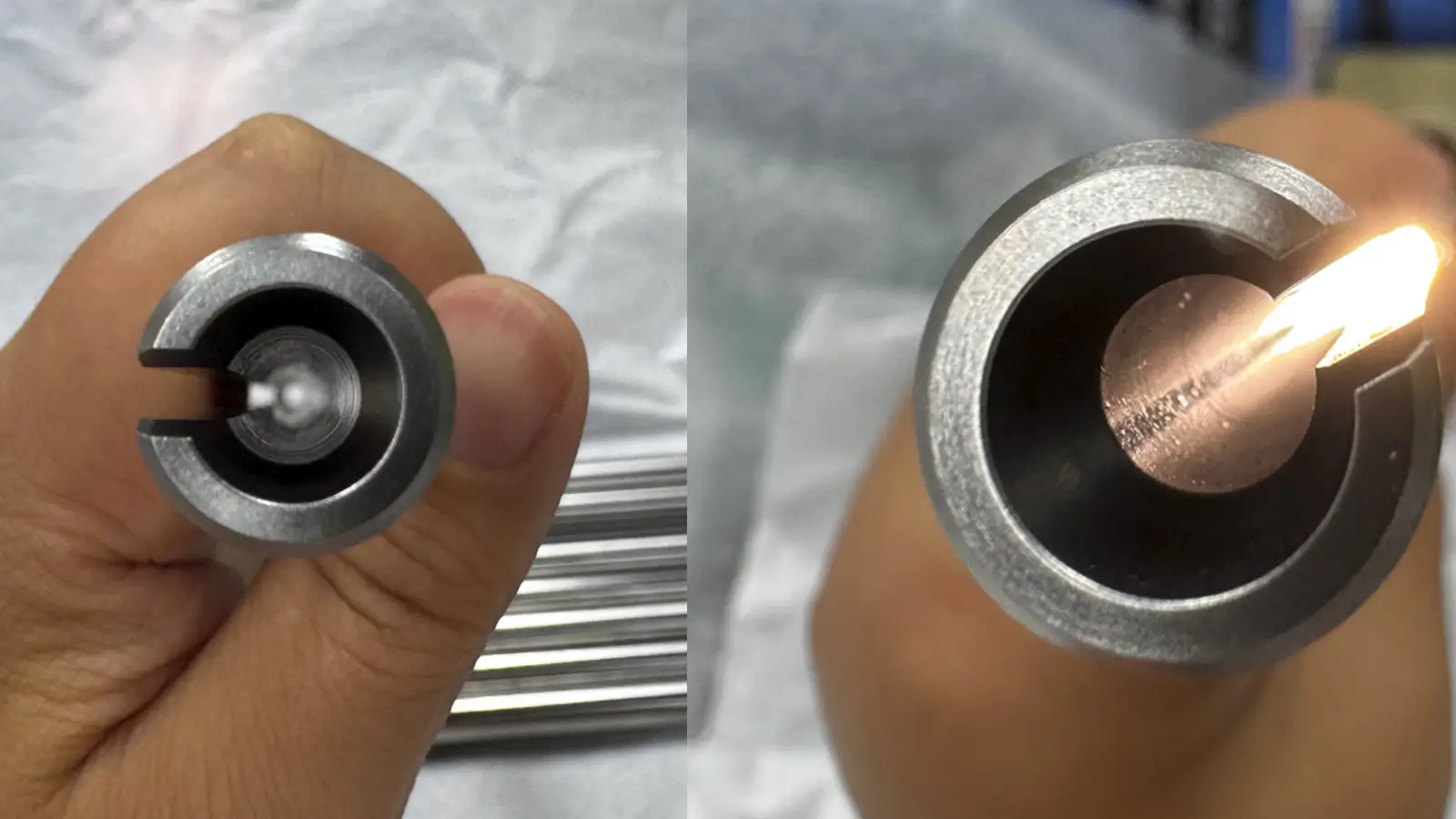
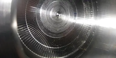
On the inside of bores, chatter marks may appear as circular or spiral waves, depending on the overhang and vibration frequency of turning tools .
Below is internal turning chatter marks.
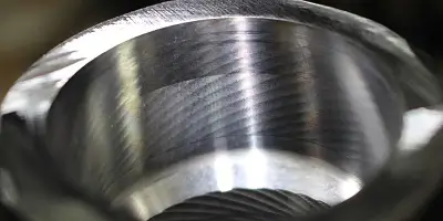
Additionally, if the chatter happens under low frequency, large and gentle ripples would appear. These marks are also called fish scale patterns.
However, if the chatter happens under high frequency, finer and tighter waves looking like wrinkled silk would appear.
Drilling chatter happens usually when the drills are long or when the workholding is unstable. The marks appear as spiral or wavy lines inside the hole, running along the length of the bore.
Below s the chatter marks during drilling.
Severe chatter can cause the drill to wobble, creating an uneven hole with irregular and jagged chatter marks on the inner surface.
CNC chatter would not occur in all conditions. The problem is closely related to the cutting tool, component, and machine itself. The common causes of machining chatter are as follows.
Tool overhang refers to the length of the tool that extends beyond the collet or chuck that holds the tool in place. Too much overhang would make the tool flexible and prone to bending or vibrating during machining process.
For example, if a 6-inch end mill with 4 inches of overhang is used to mill a deep slot, the toll will vibrate as it cuts, leaving wavy chatter marks on the slot walls.
And operators can judge if the chatter marks are caused by excessive tool overhang or not by the following signs.
The first is that the marks would get worse as the tool cuts deeper. The second is that the marks only appear when long tools are used.
A dull, chipped, or worn tool cannot cut cleanly through the material. Instead of slicing smoothly, it would bounce off the part and then create vibrations that lead to chatter marks.
Dull tools also require more force to cut, which increases stress and vibration. And chatter marks caused by this reason are often paired with poor surface finish, increased tool wear, or long cutting noises.
Stable clamping is crucial to avoid CNC chatter during the whole machining process. If the part is loose and unevenly clamped, or not supported properly, it will vibrate during cutting even if the tool is perfect.
Parts with low rigidity such as long shafts, thin sheets and hollow bores are usually faced with chatter problem. Since these components are naturally flexible, they would bend and vibrate easily under cutting forces.
If the part is inconsistent in hardness, the tool will experience sudden changes in cutting resistance. This causes the tool to vibrate, leading to chatter marks.
For instant, when machining a cast iron part with hard graphite inclusions, the tool might bounce to create irregular chatter marks at the hard spot.
In general, marks caused by uneven hardness of the part would be random or inconsistent. And they would only appear in specific areas of the part.
If the CNC machine is too old, or with loose components, it would be lack of the rigidity needed to dampen vibrations. A rigid machine stays stable during cutting, while a flexible machine vibrates easily.
And this type of chatter marks, would appear on all parts and get worse when the cutting speed is higher.
Misalignment among the CNC machine’s components can cause uneven cutting forces and vibrations. It often happens over time due to wear or improper maintenance.
And machining chatter marks caused by this problem are usually consistent across all operations.
Within a CNC machine, the spindle bearings are used to support the spindle and keep it rotating smoothly. If the bearings are worn, damaged, or dirty, the spindle will vibrate and then lead to chatter problem.
The feed of CNC machining refers to how fast the tool moves across the workpiece, and the speed of CNC machining means how fast the tool rotates.
They are both critical for smooth cutting. If they are too high or too low, they can create vibrations.
Cutting fluid helps to cool the tool and component, reduce friction, and flush away chips. Without enough cutting fluid, chatter marks would appear with discolored tooling, or chips that stick to the tool.
If the tool is applied to machine too much material in a single pass, it will experience excessive force and then vibrate during the process. This is a common problem in deep cuts or wide slots.
For CNC machining, chatter is far more than a noise issue. Continuous machining chatter can cause a series of problem such as poor finish, low efficiency, higher cost, and more. The common damage of CNC chatter are as follows.
The primary damage of CNC chatter is poor surface finish. As uncontrolled vibration occurs between the cutting tool and workpiece, it leaves repetitive ripples, waves, and uneven chatter marks across machined surfaces.
For most CNC machined parts that are always required to be smooth and clean, chatter leaves behind inconsistent surface texture. It ruins uniform smoothness and makes parts look unpolished and low-quality.
CNC machining relies on precise tool moving to hit tight dimensional tolerances. Continuous vibration will push the tool off its programmed path and then create inconsistent dimension accuracy and uneven edge profiles.
For high-precision industries like aerospace, medical, and automotive manufacturing, even minor CNC chatter can make parts completely unusable.
Machining chatter creates repetitive shock and friction on tool edges. It would accelerate wear, chipping, and premature tool breakage. A tool affected by continuous chatter will dull much faster than normal.
And faster dull means to more frequent tool replacement, and higher cost on tool. Besides, broken tools can scratch or even ruin parts.
Many machined components operate under constant mechanical stress or friction after installation. Chatter marks are not just texture defects. They act as micro cracks and stress risers on part surfaces.
These tiny wavy grooves create uneven surface tension across the component. When the part is put into service, stress concentrates on chatter indentations.
This would increase the risk of fatigue cracks, bending, or complete part failure, which is extremely dangerous for load-bearing parts, engine components, and structural hardware.
Continuous chatter does not only affect tools and workpieces, it also travels through the spindle, bearings, linear guides, and internal machine components.
Prolonged chatter would loosen machine assemblies, wear down spindle bearings, and reduce overall machine rigidity. As machine components degrade, the machine becomes less accurate.
Severe CNC chatter would generate loud squealing, excessive tool bouncing, and unstable cutting. More critically, sudden tool breakage from severe chatter can send sharp metal fragments flying, damage fixtures, or trigger machine crashes.
Since CNC machining chatter has multiple damage for tools, workpieces, and machines, it is critical to know how to effectively reduce and stop CNC chatter. Below shows certain common solution to machining chatter.
In general, adjusting machining feed and speed is the easiest and fastest way to reduce chatter.
If you notice high-pitched squealing and wavy chatter marks, try lowering your spindle speed first. If slowing down the spindle does not work, slightly increase your feed rate.
Long tool overhang makes cutting tools flexible and unstable. To stop tool chatter, it is better to use tool as short as possible.
If you must machine deep cavities that require long tools, reduce your cutting depth per pass and lower spindle speed. Additionally, it is crucial to clean the collets and tool shanks regularly.
Dull or worn tools cannot shear material cleanly and smoothly, but will lead to bouncing, rubbing, and repetitive vibration. If the cutting tools are chipped or worn enough to create severe chatter, you must replace them.
Sharp cutting edges mean to lower cutting resistance and less machine force, which can effectively reduce machining vibration.
Beside tool chatter, workpiece chatter is the common cause for CNC chatter marks. If the part is loose or unstable, even perfect tools and parameters cannot prevent chatter.
To eliminate workpiece chatter, you must secure parts with firm and balanced clamping force. For thin-walled parts and long turning shafts, use steady rests, tailstocks, and custom fixturing to add extra support.
Heavy cutting in just a single pass can put excessive stress on tools and workpieces. For deep or wide cuts, multiple lighter passes can avoid CNC chatter.
Insufficient coolant can cause excessive friction, heat buildup, and tool dulling. To reduce cutting friction and keep cutting edges sharp, it is better to apply consistent and ample coolant flow during CNC machining.
As a kind of high-precision equipment, CNC machines always need regular maintenance. To ensure overall machine rigidity, it is important to lubricate machine guide rails, check spindle runout, tighten loose assembly bolts, and replace worn spindle bearings on schedule.
For CNC machining, chatter is a type of common vibration issue. Machining chatter usually comes from the instability of tools, parts to be machined, or the CNC machine itself.
It would create chatter marks on the surface and damage both the tools and machine. To reduce and stop CNC chatter, you should indeed keep the tools and parts stable as needed.
Reducing spindle speed and increasing feed rate slightly is often the quickest way to break the vibration loop.
Because the spindle speed matches the natural frequency of the machine-tool system, causing resonance.
Yes, especially in long-reach tools and complex geometries where rigidity is reduced.

5-Axis CNC machining is a manufacturing process that uses computer numerical control systems to operate 5-axis CNC machines capable of moving a cutting tool or a workpiece along five distinct axes simultaneously.

China is the best country for CNC machining service considering cost, precision, logistic and other factors. Statistical data suggests that China emerges as the premier destination for CNC machining.

Selecting the right prototype manufacturing supplier in China is a critical decision that can significantly impact the success of your product development project.

Machining tolerances stand for the precision of manufacturing processes and products. The lower the values of machining tolerances are, the higher the accuracy level would be.