 Coordinate Measuring Machines (CMMs) are an important tool for modern measuring and inspection of parts. It can measure all three orthogonal axes to capture accurate 3D data. Below you will find a detailed description of what CMMs are, how they work, and the key benefits of CMMs.
Key Takeaways:
CMMs transform physical parts into precise digital data by capturing X, Y, Z coordinates, enabling accurate verification of dimensions, geometric tolerances (GD&T), and complex shapes against CAD models.
Choosing the right CMM is a balance of structure and technology. The main types—Bridge, Gantry, Cantilever, and Horizontal Arm—serve different part sizes and accuracy needs, while contact and non-contact probes offer flexibility for various materials and features.
CMMs are indispensable for inspecting 5-axis machined components, free-form surfaces, and parts with strict GD&T requirements that traditional tools cannot measure effectively.
Top brands like ZEISS, Hexagon, and Mitutoyo offer machines across a wide price range ($21k to $700k+), justified by their unparalleled accuracy, automation, and data-driven quality assurance for modern manufacturing.
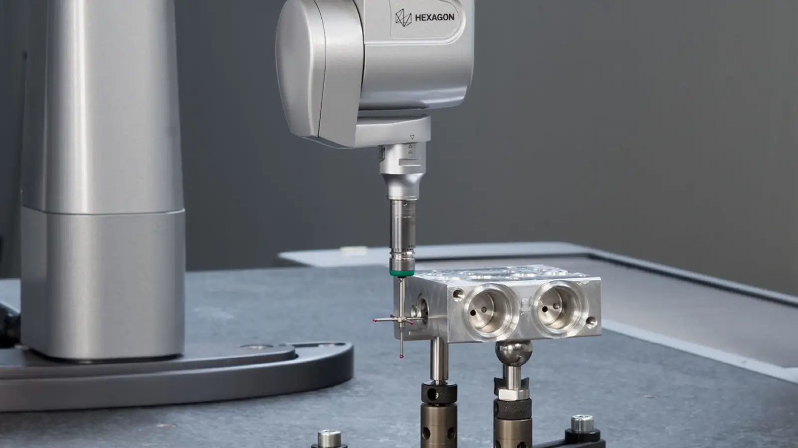
A coordinate measuring machine is a high-precision measuring device that uses a probing sensor (such as a ruby probe, optical lens, etc.) to move in three directions (X, Y, Z axes) via mechanical or non-contact probes, accurately obtaining the three-dimensional coordinates of points on a workpiece’s surface.
It then uses a software system to calculate, analyze, and compare the data, thereby completing the inspection of the workpiece’s dimensions, form, and positional tolerances.
Simply put, it is a “3D ruler” and “quality judge” that creates a “digital 3D model” of a physical workpiece and compares it with the original design drawings.
Core Functions:
Dimensional Verification: Verifies whether basic dimensions of a part, such as length, width, and height, conform to design tolerances.
Geometric Analysis: Measures complex geometric features, such as roundness, flatness, cylindricity, and geometric dimensioning and tolerancing, ensuring the part’s functionality and correct assembly.
Data Collection: Collects large amounts of point cloud data for reverse engineering or to guide the optimization of manufacturing processes.
 The history of the coordinate measuring machine (CMM) reflects the continuous pursuit of automation, high precision, and shop-floor flexibility in precision manufacturing.
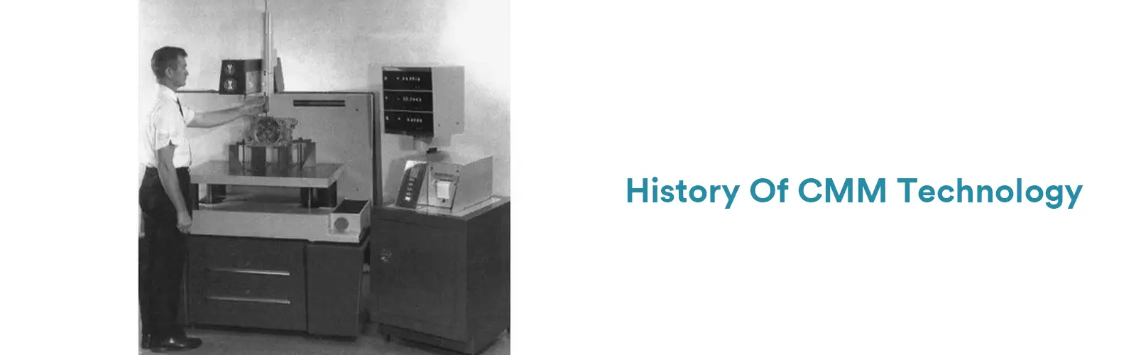
1956: Germination Period
The UK’s Ferranti Company manufactured the world’s first recognized CMM. It was modified from a three-dimensional moving milling machine, equipped with a digital readout (DRO). Operators had to manually record coordinates and calculate dimensions. At that time, the CMM was merely a “3D scale,” primarily addressing the two-dimensional measurement of complex geometric tolerances.
Early 1960s: Commercialization Stage
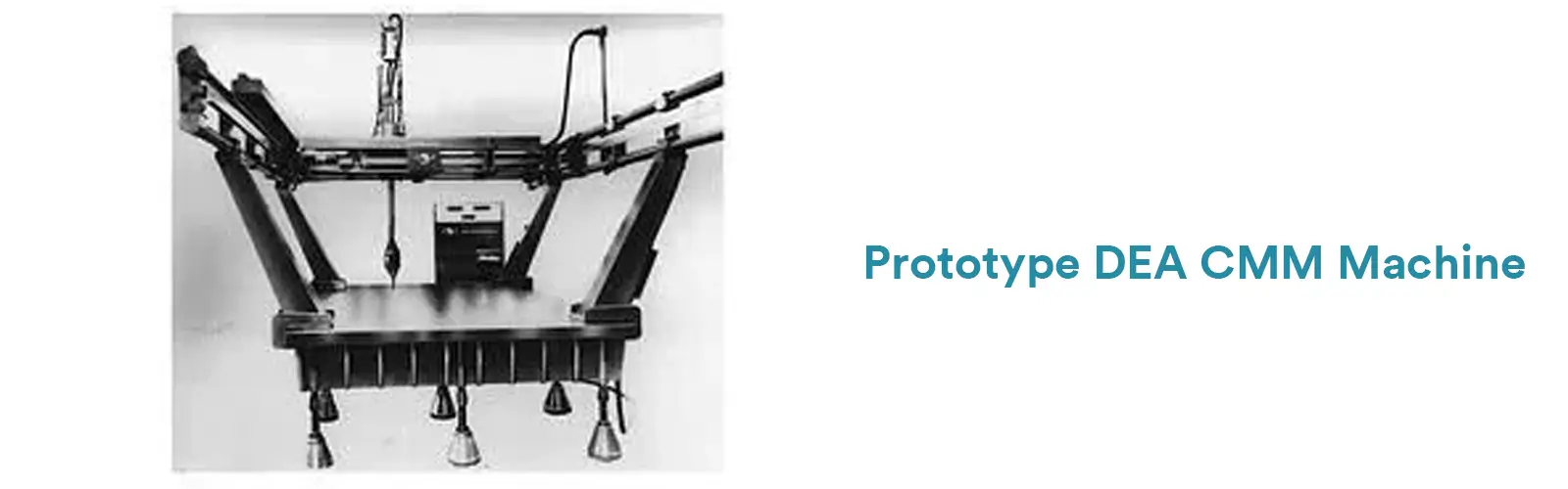 Italy’s DEA company was established and began specializing in the production of the first generation of commercial CMMs, making them dedicated metrology equipment, marking the entry of CMMs into industrial applications.
1972-1973: Touch-Trigger Probe Revolution
The UK’s Renishaw company invented the touch-trigger probe, which could quickly and reliably collect measurement points and automatically record coordinates, completely ending manual measurement and visual reading.
1960s–1990s: Computerization and Automation
The introduction of the third axis (Z-axis) enabled true three-dimensional measurement. Simultaneously, computers participated in data processing and geometric calculations, transforming the CMM into an analytical tool.
In the 1980s–1990s, CMMs integrated with CNC technology, achieving automated measurement, improving efficiency and repeatability; the standardization of Renishaw touch-trigger probes and PC-DMIS software laid the foundation for modern CMMs.
2000–Present: Intelligence and Flexibility
Technological development has focused on measurement speed, adaptability, and multifunctionality.
Modern CMMs possess high-speed continuous scanning (e.g., Zeiss VAST), multi-sensor platforms (e.g., Mitutoyo), temperature compensation functions, and can achieve near-line quality control in workshops, integrating precision measurement directly into the production site.
The CMM has evolved from a manual 2D measuring tool to a highly intelligent 3D digital metrology center, epitomizing the manufacturing industry’s shift from experience-based control to data-driven quality management.
The working principle of a coordinate measuring machine is based on a simple yet powerful mathematical concept: the Cartesian coordinate system.
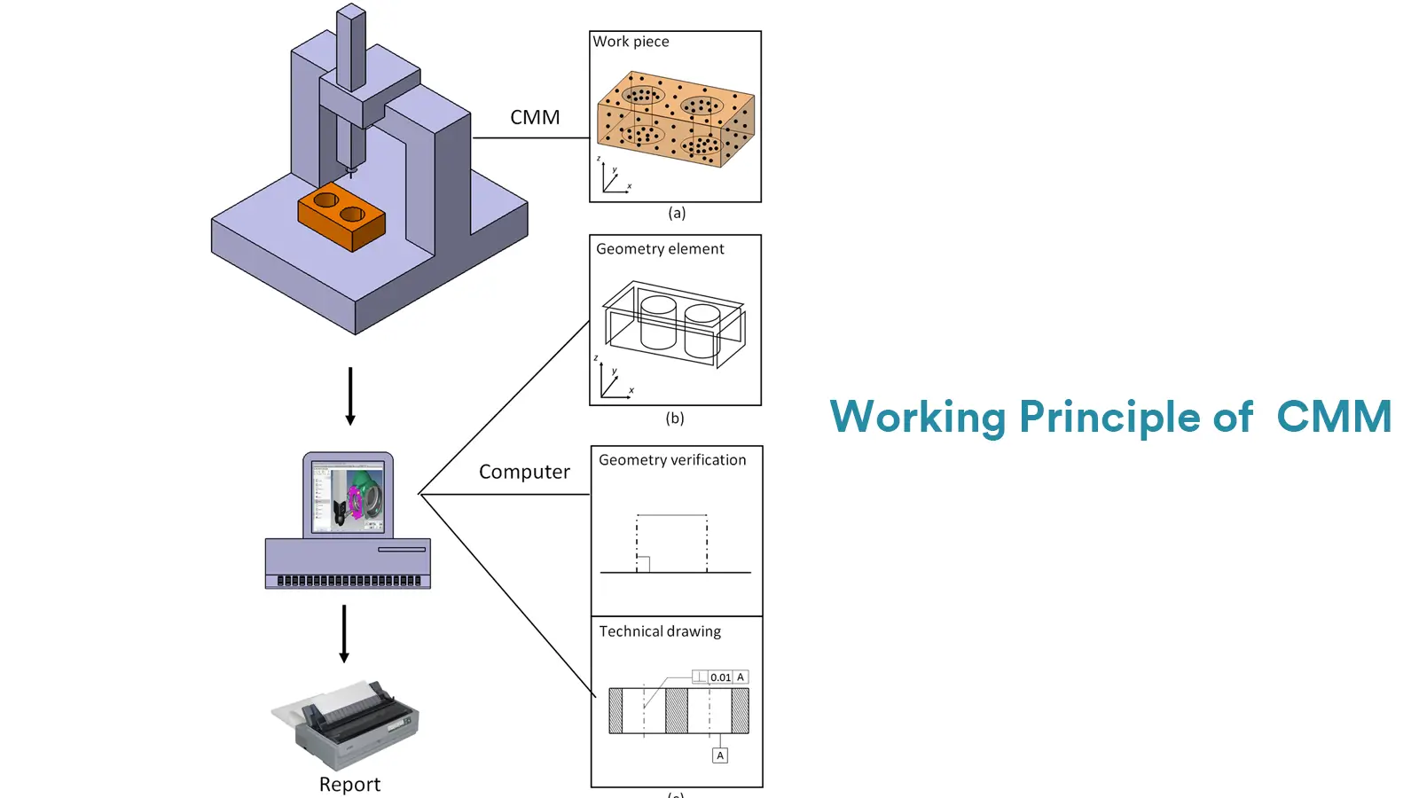
Within a precisely defined three-dimensional space, an ultra-sensitive probe touches the surface of the workpiece, accurately recording the three-dimensional coordinate values of each contact point.
Then, powerful software fits these discrete points into characteristic elements, based on which precise calculation and comparison of dimensions, form, and position are performed.
This process can be specifically divided into three core steps:
This is the foundation of all measurements.
The CMM itself has a machine coordinate system, established based on the scales of the three-axis grating rulers.
However, the placement of the workpiece is often arbitrary. Therefore, the operator or software needs to establish a workpiece coordinate system that is completely consistent with the design drawings by measuring datum features (such as a plane, hole, or sphere) on the workpiece or fixture.
This is like telling the CMM: “Please use the center of this hole as the origin and this edge as the X-axis to understand and measure this part.”
Positioning and Probing: Under computer control, the CMM drives the probe system to move near the workpiece.
Triggering or Scanning
Touch-Trigger Measurement: The probe moves in a point-to-point manner. When the ruby probe tip contacts the workpiece surface, the probe “triggers” a signal.
At that very moment, the CMM immediately reads the scale values of the X, Y, and Z-axis grating rulers, thereby recording the three-dimensional coordinates of that point.
Continuous Scanning (represented by ZEISS technology): While maintaining contact with the workpiece surface, the probe moves continuously along the contour with constant measuring force.
During this time, the CMM records the readings of the grating rulers at a very high frequency (can collect hundreds or even thousands of points per second), thereby obtaining massive, high-density “point cloud” data.
This is the key step in converting raw data into valuable information.
Feature Construction: The software fits the collected discrete coordinate points into basic geometric elements using mathematical models. For example, using three points to define a circle, and multiple points to define a plane or cylinder.
Dimensional and Geometric Tolerance Evaluation: Based on the constructed geometric elements, the software can automatically calculate:
Dimensions: Such as the diameter of a hole, the distance between two planes.
Form Tolerances: Such as straightness, flatness, roundness, cylindricity.
Position Tolerances: Such as parallelism, perpendicularity, position, concentricity.
Report Output: Finally, the software generates a detailed inspection report, usually in the form of graphical comparison (color deviation maps) and data tables, visually showing which areas of the workpiece are qualified and which are out of tolerance.
The working principle of a CMM is a closed-loop process of “positioning – acquisition – calculation”. Its core lies in accurately obtaining the spatial coordinates of points, transforming complex physical workpieces in the real world into quantifiable and analyzable data models in the digital world.
The Coordinate Measuring Machine (CMM) is a sophisticated piece of equipment that integrates mechanical, electronic, optical, and computer technologies into a single high-precision measurement system.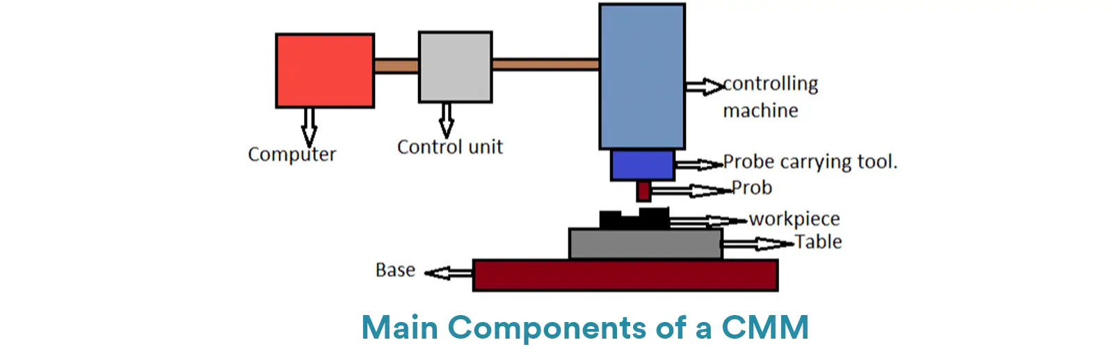
A CMM is typically composed of four core systems, plus essential auxiliary components: the Mechanical System, the Probing System, the Control System, the Software System, and the Environmental/Auxiliary System.
This is the CMM’s physical framework, responsible for achieving precise 3D movement. The mechanical system provides the structure and motion necessary for measurement.
4.1.1. Main Structure (The Frame):
The main structure provides rigidity and stability.
Common structural types include:
4.1.2. Guideways and Bearings:
Ensure smooth and precise motion along each axis. Air bearings are commonly used to achieve virtually frictionless movement, coupled with precision mechanical guideways.
4.1.3. Drive System:
Typically uses servo motors with precision ball screws or toothed belts to drive the movement of each axis.
4.1.4. Position Scales (The Ruler):
This is the device’s “ruler.” High-precision linear optical encoders (scales) are used, often with resolutions down to the micron or even nanometer level, directly determining the machine’s accuracy.
This is the part that directly interacts with the workpiece and is often considered the heart of the CMM. It includes the probe head, the stylus, and automated changing capabilities.
Generally divided into two categories:
Touch-Trigger Probes: Acts as a highly sensitive “switch.” It triggers a signal upon contact with the workpiece, enabling fast, single-point measurement. (Representative Brand: Renishaw).
Scanning Probes: Capable of continuously collecting data points while maintaining contact with the surface. They are highly efficient and essential for measuring complex contours and free-form surfaces. (Representative Brand:ZEISS VAST series.
These are typically interchangeable assemblies featuring a ruby sphere mounted on a shaft. Ruby is the material of choice due to its extreme hardness and resistance to wear.
Allows the CMM to automatically switch between different stylus lengths and angles within a measurement program, enabling the inspection of hard-to-reach features without operator intervention.
This system is responsible for coordinating mechanical movement and signal processing.
Control Cabinet: Contains the electronics for driving the motors and receiving signals from the probes and encoders.
Control Software: Interprets the user’s measurement program, translating it into precise motion instructions for the motors, and processes the real-time data received from the linear scales and the probe head.
This is the user interface that transforms raw data into valuable inspection information.
Programming: The creation of automatic measurement paths, often done by importing a CAD model.
Construction and Calculation: Fitting the measured points to form geometric elements (circles, planes, etc.) and calculating the corresponding dimensions and geometric tolerances GDT.
Data Analysis and Reporting: Generating intuitive reports, often featuring vivid color deviation maps and data tables, which clearly show pass/fail statuses. (Leading Software: ZEISS CALYPSO, Hexagon PC-DMIS.
Granite Plate: Serves as the stable measuring base. It offers exceptional stability, thermal consistency, and flatness for the machine’s foundation.
Temperature Control System: Precise measurement requires a constant temperature (typically 20 degrees) to eliminate errors caused by the machine’s and part’s thermal expansion and contraction.
Computer and Peripherals: Used for running the software, analyzing data, and outputting the final inspection reports.
CMMs come in a variety of designs and configurations to meet different inspection needs.
They can be categorized in two primary ways — by mechanical structure and by measurement method.
This is the most common and fundamental way to classify CMMs.
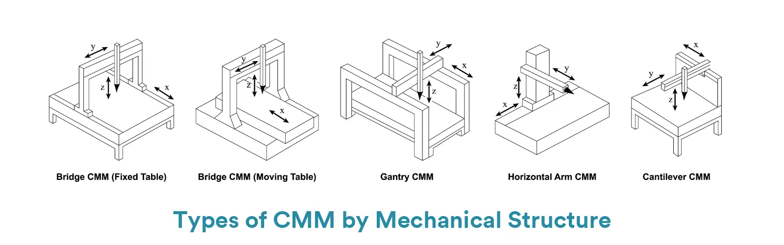
The main types include Bridge-type, Gantry-type, Cantilever-type, Horizontal-arm-type, and Portable CMMs.
The bridge-type design is the most classic and widely used structure.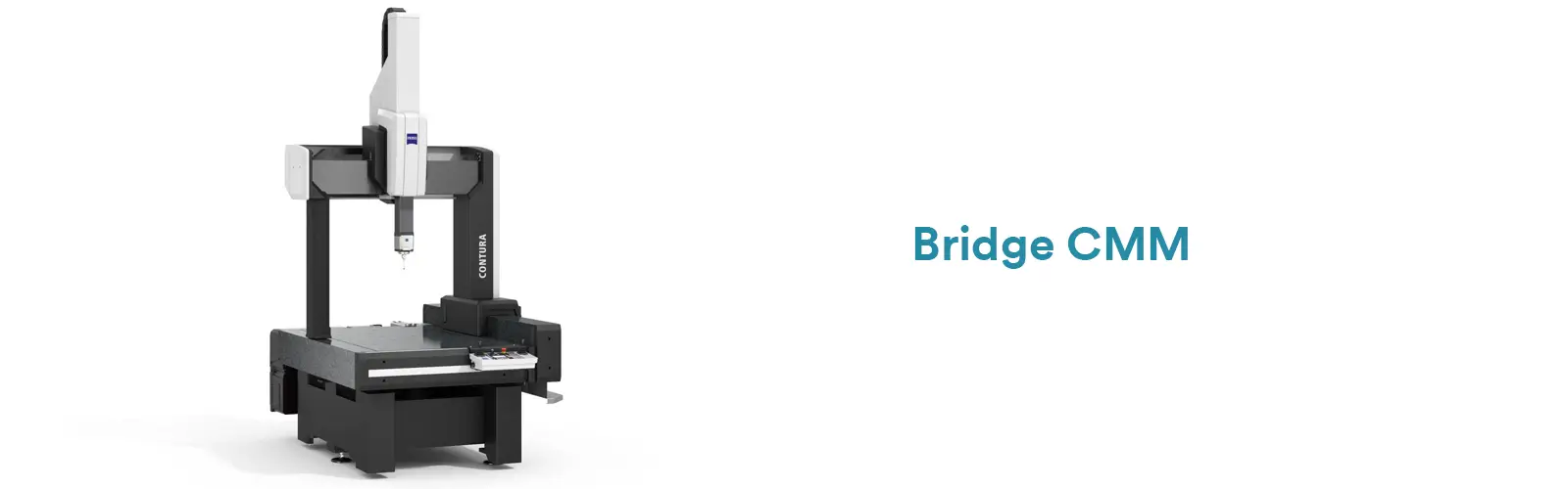
The moving bridge travels along the Y-axis over a fixed granite table, while the carriage moves along the X-axis, and the Z-axis spindle moves vertically.
It offers excellent all-around performance and is the standard choice for quality labs and precision manufacturing workshops.
Advantages:
High accuracy, strong rigidity, mature technology, and good cost-performance ratio.
Disadvantages:
The moving bridge creates higher inertia, requiring a solid foundation and careful dynamic accuracy control.
The gantry-type CMM can be viewed as a large, fixed version of the bridge design.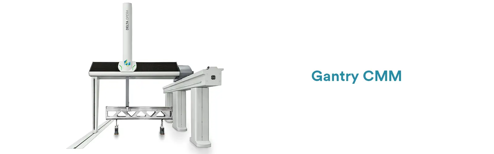
It features a rigid gantry frame, with either the worktable moving underneath along the Y-axis or the gantry itself moving.
This configuration is ideal for large workpieces, such as automotive body frames, aircraft structures, and large molds.
Advantages:
Extremely stable structure and excellent rigidity — perfect for large-scale measurements in automotive and aerospace industries.
Disadvantages:
Requires large floor space and higher investment cost.
In a cantilever-type CMM, the probe is mounted on a single arm that moves vertically (Z-axis) and can rotate around it.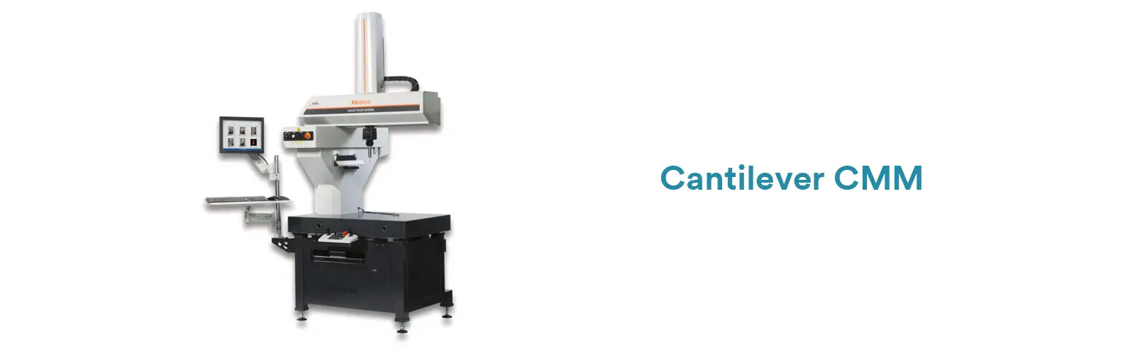
It is often used for fast inspection of small and medium-sized parts directly on the production floor.
Advantages:
Very open structure, easy for part loading/unloading, and convenient manual operation.
Disadvantages:
Lower rigidity compared to bridge or gantry types, resulting in reduced accuracy.
The horizontal-arm CMM features a probe mounted on a horizontally extending arm, similar to a desk lamp.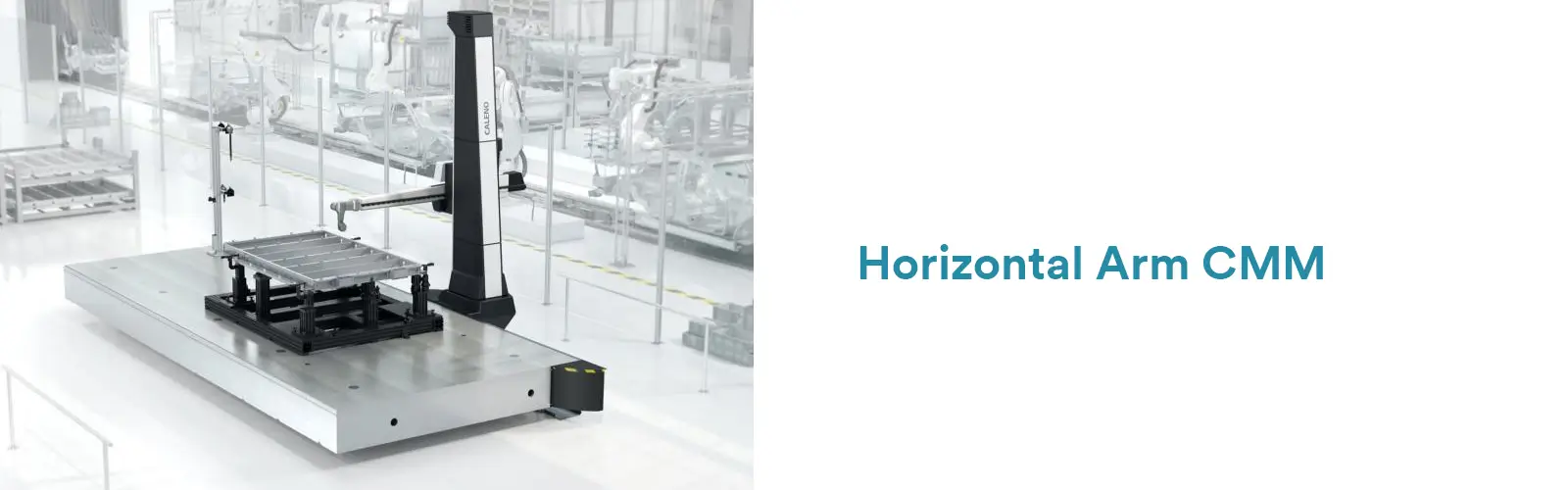
There are both fixed-arm and movable-arm versions. This configuration is the main solution for inspecting automotive body-in-white (BIW) and other large sheet metal or panel parts.
Advantages:
Excellent for thin-wall and wide parts, as the long Z-axis travel allows measurement without interference.
Disadvantages:
Lower rigidity in the Y direction can affect precision.
Portable CMMs include articulated arm CMMs (which move like a human arm with multiple joints) and optical tracking systems.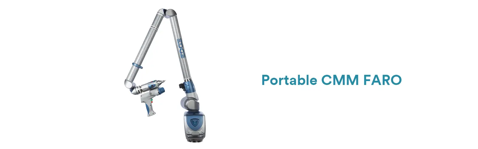
They are primarily used for on-site or in-line inspection in production environments or on very large components such as aircraft, ships, or heavy machinery.
Advantages:
Highly flexible, easy to transport, and can measure directly on the workpiece — ideal when parts cannot be moved to a fixed CMM.
Disadvantages:
Typically, lower accuracy than stationary CMMs, and the measurement range is limited by arm length or optical line of sight.
CMMs can also be categorized based on how they collect data — either through contact or non-contact measurement.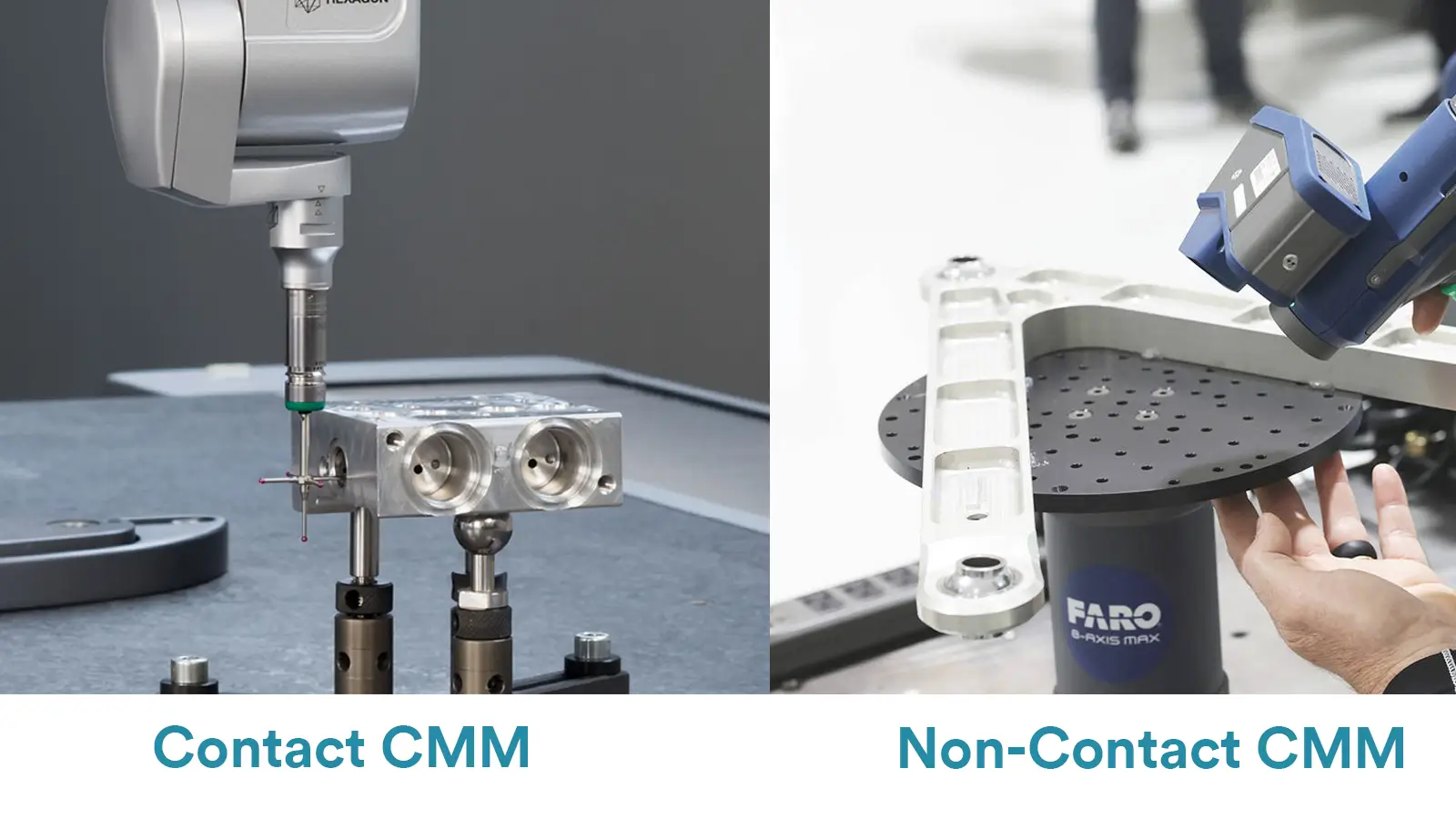
The traditional and most common method, using a physical probe to touch the workpiece surface and record coordinate data.
All the mechanical structures mentioned above can be equipped as contact-type CMMs.
Instead of physical touch, optical, laser, or vision sensors are used to measure the surface.
Advantages:
Fast measurement, no risk of surface damage or deformation from probe pressure, and ideal for soft, delicate, or highly reflective materials.
Disadvantages:
Generally less accurate than contact systems and can be affected by surface color or reflectivity.
Typical technologies of non-contact CMM:
Laser scanners
Structured light scanners
Optical vision measuring systems
Each CMM type has unique strengths, from the ultra-precise bridge type to the flexible portable systems. Choosing the right CMM depends on your application, part size, required accuracy, and production environment.
Modern metrology often combines both contact and non-contact CMM technologies to balance speed, flexibility, and precision — achieving the most efficient inspection workflow possible.
CMMs play a critical role in quality control because of their exceptional precision, versatility, and powerful data analysis capabilities.
CMMs set the benchmark for contact-based measurement accuracy, achieving results down to the micron or even submicron level.
This level of precision is essential in industries such as aerospace, automotive, and medical device manufacturing, where tight tolerances are non-negotiable.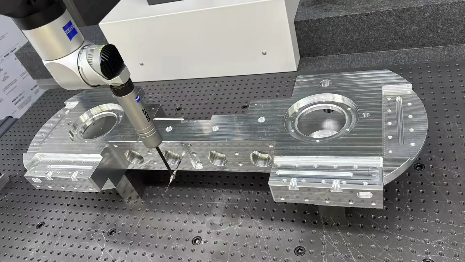
Once a program is set up, the machine can repeat the same measurement with identical precision as many times as needed—eliminating operator inconsistency and human error.
A CMM is not just a measuring device—it’s a comprehensive data acquisition and analysis system.
It can instantly compare the measured data to the CAD model and generate intuitive color maps (deviation plots) that show where a part is out of tolerance.
In addition, it can automatically generate detailed inspection reports including dimensional results and GD&T data, simplifying documentation and traceability in quality control.
Traditional tools such as calipers or micrometers struggle with complex freeform surfaces, turbine blades, or gears.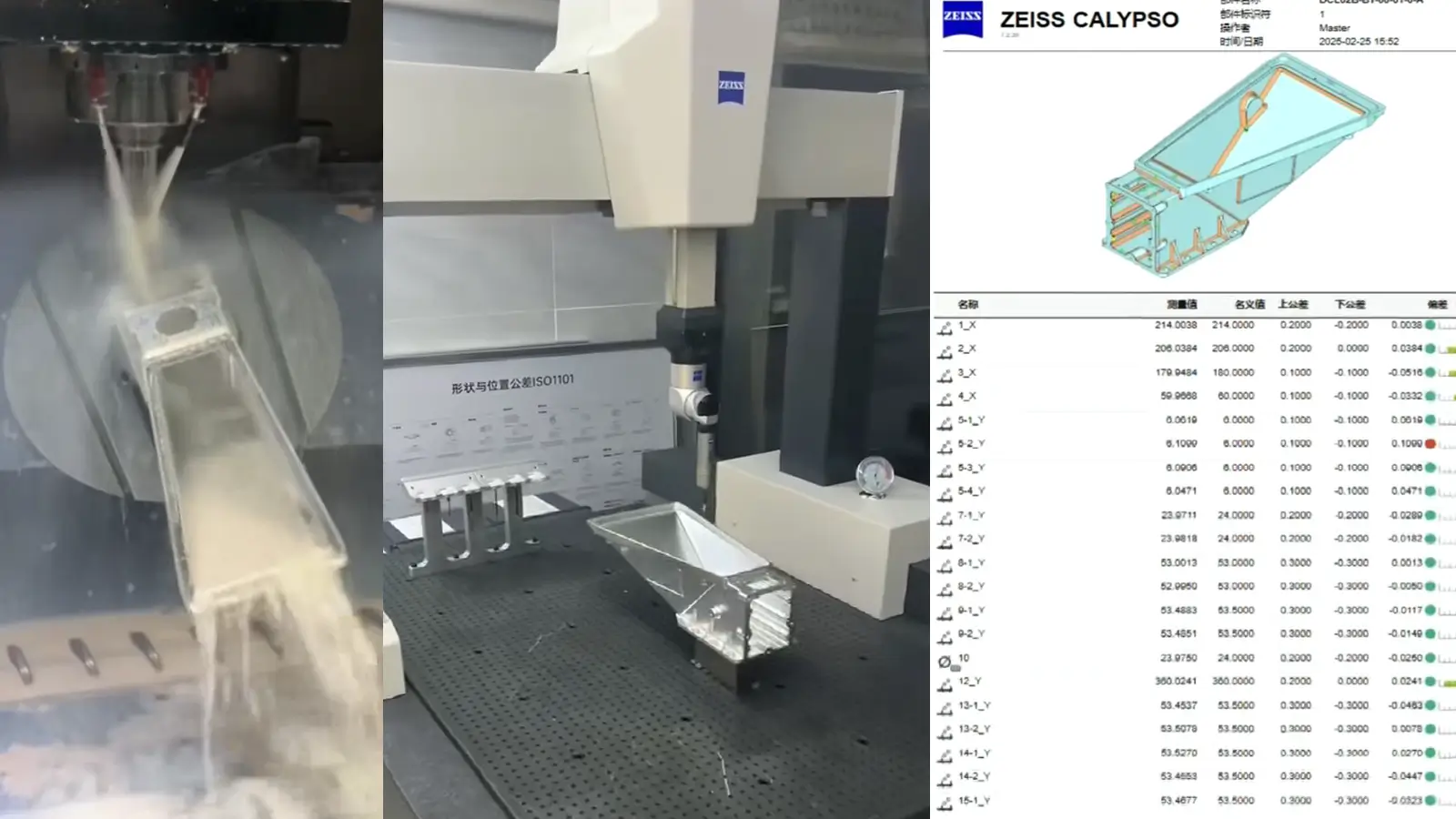
CMMs can collect dense point clouds to accurately reconstruct the 3D geometry of these parts and evaluate them with high confidence.
Once the first part is programmed, batch inspection becomes extremely fast—far quicker than manual measurement.
CMMs can also be integrated with robots and automatic loading systems to perform fully automated, inline, or offline inspections, making them a core part of smart manufacturing and lights-out factories.
Automation minimizes dependence on skilled operators and eliminates variations caused by fatigue, skill level, or judgment, ensuring consistent and reliable inspection results.
By switching between different types of probes (trigger, scanning, or optical), a single CMM can handle various workpieces and inspection tasks, making it suitable for a wide range of applications.
Despite their benefits, CMMs also have some limitations that should be considered before investing.
High-precision CMMs are expensive, typically ranging from tens of thousands to several hundred thousand dollars.
They also require a controlled environment, a solid foundation, and regular calibration—all of which increase the total cost of ownership.
CMM accuracy is highly sensitive to temperature, humidity, vibration, and air flow.
That’s why they are usually installed in a dedicated, climate-controlled metrology room, which limits their use directly on the shop floor.
For parts that only need a few basic dimensions checked, the setup time (fixturing and coordinate alignment) may take longer than using simple gauges or hand tools—making a CMM feel like “overkill.”
Developing efficient and accurate measurement programs requires professional knowledge.
Operators must also be trained to interpret results correctly, which adds to the skill barrier.
Because the probe has a physical radius, the system measures the center of the stylus ball rather than the true surface of the part—requiring precise radius compensation.
Even minimal contact force can deform soft materials like rubber or plastic, causing distorted results.
Additionally, deep holes, narrow slots, or fragile features may be inaccessible to the probe.
Traditional touch-trigger probes collect discrete points, which means surface defects such as scratches or bumps may go undetected.
Scanning probes can overcome this issue by continuously collecting data—but at a higher cost and with greater data-processing complexity.
The top 5 global CMM brands include ZEISS, Hexagon, Wenzel, Mitutoyo, and FARO.
ZEISS is a benchmark for technological innovation and high precision, holding a leadership position especially in the automotive, aerospace, and medical industries.
Key Characteristics:
Technology Pioneer: A leader in scanning probes, optical measurement, and multi-sensor technology.
Powerful Software: Its proprietary CALYPSO software is renowned for its user-friendliness and powerful features, seamlessly integrating with ZEISS hardware.
Stability: Offers exceptional long-term stability thanks to superb mechanical design and materials science (e.g., ceramic guideways).
Ecosystem: Provides a complete solution, from metrology software and scanning probes to industrial computed tomography.
Key Model Series:
ACCURA: The flagship bridge-type CMM. Uses “active scanning technology” to adjust probing force in real-time during scanning, ensuring high accuracy and efficiency. Ideal for high-standard labs and advanced manufacturing.
CONTURA: A best-selling model. Based on the ZEISS VAST XT Gold scanning technology, it offers excellent performance and flexibility in both moving-bridge and fixed-bridge configurations, with a high cost-performance ratio.
SPECTRUM: An economical touch-trigger CMM, perfect for users focused primarily on dimensional inspection who don’t require extensive scanning. It’s the entry point into the ZEISS ecosystem.
DURAMAX: A rugged CMM designed specifically for the shop floor, with excellent temperature and vibration compensation, allowing it to be used directly in production environments.
Hexagon is a metrology giant with the broadest product portfolio and massive market share, formed through the acquisition of several renowned brands.
Key Characteristics:
Diverse Brands & Products: Encompasses multiple sub-brands, covering almost every need from the quality lab to the production line.
Software Leader: Its PC-DMIS is one of the most widely used CMM software platforms globally, known for its powerful capabilities.
Comprehensive Technology: Offers a full range of solutions from bridge and gantry CMMs to portable measuring arms.
Leitz Heritage: The acquired Leitz brand represents ultra-high-performance metrology, designed for the most demanding measurement tasks.
Key Model Series:
LEITZ PMM-G: The ultra-high-precision flagship. A fixed gantry CMM using highly stable materials, typically placed in a climate-controlled room for measuring extremely high-tolerance parts like turbine blades and precision gears.
GLOBAL S: The best-selling high-performance bridge CMM series. Known for its “patented strain-free” design and thermal insensitivity, it maintains high accuracy while being more forgiving of environmental variations, making it very practical.
BRAVO: An economical bridge CMM for small and medium-sized enterprises, offering good entry-level performance and reliability.
ROMER Absolute Arm: A world-leading portable articulated measuring arm. Paired with laser line scanners, it is ideal for inspecting the contours and surfaces of large parts on-site.
Wenzel is representative of ultra-high performance and unique technology, focused on solving the most demanding measurement challenges, especially for large and ultra-precision applications.
Key Characteristics:
Master Craftsmanship: Renowned for exceptional mechanical manufacturing, extensively using granite, ceramic, and other low-thermal-expansion materials for inherent stability.
Unique Designs: Offers various unique structures like gantries and horizontal arms to meet special measurement needs.
Ultra-High Precision: Its flagship models are chosen by national metrology institutes and top-tier manufacturing companies.
Technical Focus: Focuses on reaching the pinnacle of high-precision CMM technology rather than pursuing broad market width.
Key Model Series:
Wenzel CORE: An ultra-high-performance fixed bridge CMM. The entire mechanical structure (bridge and guideways) is made from solid granite, providing unmatched rigidity and thermal stability.
Wenzel LH: A large gantry CMM for measuring extra-large parts like aircraft fuselages, car bodies, and large molds.
Wenzel XOrbit: A unique horizontal CMM specifically optimized for measuring complex rotationally symmetrical parts like high-precision gears and turbine blades, avoiding probe orientation errors caused by gravity.
Mitutoyo is a global leader in precision measurement, known for exceptional reliability, durability, and user-friendliness, with a particularly strong presence in the Asian market.
Key Characteristics:
Reliable Quality: Mitutoyo instruments are famous for being “robust” and maintaining long-term stability.
Strong Probe Technology: Its MH-series scanning probes offer excellent performance, delivering high-speed, high-accuracy scanning.
Complete Product Line: Offers a full range from micrometers and calipers to ultra-precision CMMs, with a highly integrated software ecosystem.
Wide Application: Used extensively across many industries like automotive, electronics, and precision engineering.
Key Model Series:
CRYSTA-Apex S: The flagship scanning series. Equipped with the latest MHT-CNV scanning probe, it enables “5-axis synchronized scanning” with outstanding speed and accuracy. The main model for high-end applications.
LegEX: A high-accuracy, high-rigidity gantry CMM for measuring large molds and body panels.
MACH-VM Series: A shop-floor CMM series with good dust, moisture, and vibration resistance, designed for harsh production environments.
FARO is an absolute leader in portable measurement.
Portable Measurement Expert: The FARO Arm (portable articulated arm) is one of the world’s most renowned portable CMMs, competing directly with Hexagon’s ROMER arm.
Laser Tracker Leader: Its FARO Laser Tracker is an industry standard for large-scale metrology, used in the assembly of aircraft, ships, and large machinery.
Focus on On-Site Solutions: Its strength lies in bringing measurement capability to the part, rather than moving the part to the machine.
Top 5 Global CMM Brands List
| Brand | Country | Core Advantages | Representative Models | Typical Application Fields | Approximate Price Range (USD) |
|---|---|---|---|---|---|
| ZEISS | Germany | Benchmark in technological innovation and high precision; powerful CALYPSO software; complete metrology ecosystem. | ACCURA, CONTURA, SPECTRUM | Automotive engines, aerospace components, precision medical instruments, high-standard laboratories. | $110,000 – $690,000+ |
| Hexagon | Sweden | Widest product line, high market share; universal PC-DMIS software; full-range solutions from metrology lab to shop floor. | LEITZ PMM-G, GLOBAL S, ROMER Absolute Arm | General manufacturing, automotive components, large molds, body-in-white inspection. | $69,000 – $550,000+ (Portable arm priced separately) |
| Wenzel | Germany | Exceptional performance; craftsmanship-level build quality; full granite/ceramic structure; excellent long-term mechanical stability. | CORE, LH, XOrbit | National metrology institutes, high-standard gears, turbine blades, precision molds. | $207,000 – $690,000+ |
| Mitutoyo | Japan | Outstanding reliability and durability; advanced scanning probe technology (MH series); user-friendly and stable quality. | CRYSTA-Apex S, LegEX, MACH-VM | Precision electronics, automotive components, general precision manufacturing, quality inspection labs. | $55,000 – $345,000 |
| FARO | USA | Leader in portable measurement systems; laser trackers are the industry standard; focused on on-site measurement solutions. | FARO Arm, FARO Laser Tracker | Large equipment/aircraft/ship assembly, reverse engineering, in-machine inspection, jig and fixture validation. | Portable arm: $28,000 – $110,000 Laser tracker: $69,000 – $207,000+ |
The price of a Coordinate Measuring Machine (CMM) varies depending on several factors, including the brand, model, measuring range, accuracy level, degree of automation, and whether it’s new or pre-owned.
Generally, the CMM market can be categorized into three main tiers.
| Level | Approximate Price Range (USD) | Description |
|---|---|---|
| Entry-Level / Economy | $21,100 – $70,400 | Primarily used for dimensional inspection. Typically employs touch-trigger probes, has smaller measuring ranges, and offers moderate accuracy. Suitable for basic inspection in small and medium-sized enterprises, education, or workshop environments. |
| Mid-Range / Mainstream High-Performance | $70,400 – $211,300 | The mainstream workhorse in the market. Often equipped with scanning probes, providing high accuracy, fast speed, and powerful software. Ideal for precision inspection in industries like automotive, aerospace, and precision mold making. |
| High-End / Ultra-High Performance | $211,300 – $704,200+ | Features fixed-bridge or gantry structures and uses special materials (e.g., ceramic, granite) for ultra-high precision and stability. Typically used in metrology institutes, national laboratories, and applications with extreme precision requirements. |
When purchasing a CMM, there are several additional costs to consider beyond the machine itself:
Sensors and Probe Systems:
Basic touch-trigger probes are the most affordable option. However, continuous scanning probes or 5-axis REVO systems can increase the overall price by 20% to 50%.
Software Modules:
Most machines come with basic measurement software, but advanced modules—for CAD model comparison, complex surface analysis, and automated programming—require additional licenses and fees.
Environmental Control:
For high-precision measurements, a temperature- and humidity-controlled metrology room is essential. Setting up or upgrading such a facility can add 10% to 30% to the machine’s cost.
Installation, Training, and Calibration:
Include costs for initial installation, operator training, and annual calibration services in your total budget.
When planning your investment, don’t just look at the machine’s listed price—consider the complete system solution and long-term operating costs to ensure a realistic budget.
Certain CNC parts require Coordinate Measuring Machine (CMM) inspection because their design involves levels of complexity, precision, or functional requirements that traditional measuring tools (such as calipers and micrometers) simply cannot handle.
This is the primary reason. The more intricate a part’s geometry, the greater the reliance on a CMM.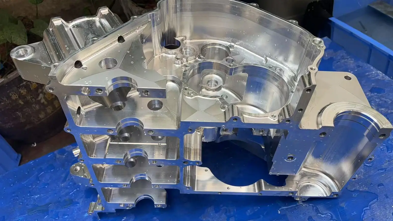
Free-Form Surfaces and Irregular Shapes:
Parts like aerospace blades, medical implants, or automotive molds contain complex, non-regular free-form surfaces. Traditional tools cannot verify the surface profile of these contours. Only a CMM can capture high-density point clouds and digitally compare them directly against the CAD model to validate the deviation of the entire surface.
Complex Hole Patterns and Deep Cavities:
A part may contain multiple holes with extremely strict positional requirements, often located inside deep cavities. It is difficult for calipers or bore gauges to maintain stable positioning or ensure the correct measurement direction within these deep features. The CMM can precisely probe these hard-to-reach features using various extensions and angled probes.
Many functional tolerances in CNC parts are interrelated—meaning they must be mathematically calculated based on datums. This capability is beyond the scope of traditional measuring tools.
Strict True Position Requirements:
When the positional tolerance of a hole is tight (e.g., less than 0.1 mm or lower), it requires accurately determining the hole’s center line’s true spatial location relative to the part’s datums (like three mutually perpendicular planes). Only a CMM can establish these datums and perform the complex 3D vector calculations required for positional verification.
Coaxiality and Perpendicularity:
Verifying the coaxiality of bearing bores or the perpendicularity of mounting faces requires simultaneously measuring multiple geometric features and performing complex mathematical fitting and tolerance calculations. These are inherent functions of CMM software.
For parts with extremely tight tolerances, the CMM provides the highest level of confidence and proof of quality.
Micron-Level Tolerances:
When part tolerances are at the micron level, the measurement uncertainty, probing force, or inherent accuracy of traditional tools are insufficient. The CMM, relying on high-precision linear encoders and frictionless air bearings, delivers lower measurement uncertainty and higher repeatability.
Quality Traceability:
Measurement results for critical CNC components (such as aerospace engine or medical device parts) must have traceable digital records. The CMM automatically generates standardized, unalterable reports, fulfilling strict regulatory requirements for documentation and traceability in these industries.
When the quality requirements of a CNC part move beyond simple, discrete, non-interrelated dimensional checks—that is, when they involve complex shapes, strict GD&T, or extremely high precision—the CMM becomes the mandatory inspection tool.
Modern 5-axis CNC machining can create these complex, high-precision parts, but this complexity increases the inspection challenge.
The CMM, as a high-precision 3D measurement tool, perfectly complements 5-axis machining by ensuring the part’s dimensions, geometric tolerances, and surface accuracy meet design standards.
This is why the CMM and 5-axis machining form an indispensable partnership in modern precision manufacturing, leading more 5-axis facilities to invest in CMM equipment.
Related blog: What is 5 CNC Machining? -Everything You Want To Know
The CMM inspection process for CNC parts involves pre-inspection preparation, workpiece fixturing and alignment, probe selection and qualification, coordinate system establishment, measurement execution, and data analysis and reporting.
This foundational stage ensures measurement success. Inadequate preparation can lead to invalid results.
Carefully review engineering drawings to identify all required dimensions, geometric tolerances (e.g., flatness, circularity, position), and datums.
Obtain the part’s 3D CAD model (e.g., STEP, IGES format). This is essential for offline programming and automated comparison analysis.
Determine measurement priorities: Identify critical and functional dimensions.
Plan the measurement strategy: How many points are needed to measure a plane or a circle? How should the measurement path be planned to avoid collisions with the part?
Online Programming: Manually operating the probe on the CMM for the first measurement while generating the program. Suitable for simple parts or one-off inspections.
Offline Programming (Recommended):
Using dedicated inspection software (e.g., PC-DMIS, CALYPSO) to simulate and write the entire measurement program on a computer using the CAD model.
This significantly reduces machine downtime, improves efficiency, and avoids collision risks. The program is transferred to the CMM for execution.
Cleaning:
Thoroughly clean the CMM table and the CNC part. Any chips, oil, or dust can cause measurement errors.
Fixturing:
Use dedicated fixtures, magnetic bases, jack stands, and other tools to securely stabilize the part on the table.
Principles of Fixturing:
Secure & Stable: Ensure the part does not move during measurement.
No Over/Under-Constraint: Follow the “3-2-1” locating principle to avoid part deformation caused by fixturing.
No Obstruction: The fixturing method must not obstruct the probe from reaching the features to be measured.
Probe & Stylus Selection:
Select the appropriate probe (e.g., touch-trigger or scanning) and stylus (e.g., star, cylindrical) based on the features to be measured (e.g., deep holes, small surfaces), considering stylus length and diameter.
Probe Qualification:
This is a critical step. The probe is used to touch a reference sphere of known precise diameter from various angles.
The purpose is to accurately calculate the effective diameter and positional relationship of the probe tip (ruby sphere), enabling the software to perform correct “tip radius compensation” in subsequent measurements. Data from an unqualified probe is unreliable.
This is the core of CMM measurement, aiming to align the CMM’s machine coordinate system with the part’s design coordinate system, typically following the “3-2-1” principle.
Leveling (3 Points):
Measure a plane (usually Datum A) with at least 3 points. This plane establishes the primary datum, defining the Z-axis orientation and origin.
Rotation (2 Points):
Measure a line (usually Datum B, like a line or cylinder) with at least 2 points. This defines the X-axis orientation, rotating the coordinate system into alignment with the part.
Origin (1 Point):
Measure a point (usually Datum C, like a hole center) and set it as the coordinate system origin (0,0,0).
Once established, the software knows the exact position and orientation of the part in space, and all subsequent measurements are calculated and evaluated within this unified coordinate system.
Measurement Execution:
Execute the prepared measurement program. The CMM automatically moves the probe, collecting points from various features (holes, faces, slots, surfaces) according to the predefined path and number of points.
The operator must monitor the initial run to prevent collisions.
Data Analysis & Report Generation:
Automatic Calculation:
The software automatically calculates feature dimensions, form, and position based on the collected points (e.g., 3 points define a plane, 4 points define a circle).
CAD/Nominal Value Comparison:
The software compares the actual measured values with the theoretical values from the CAD model, calculating the deviations.
Report Generation:
Upon completion, the software automatically generates a detailed inspection report, typically including:
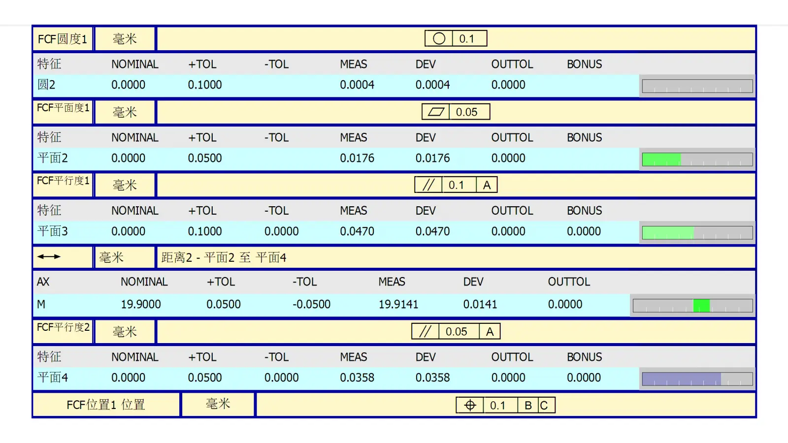
Tabular Report:
Lists the nominal value, measured value, deviation, and result (OK/NG) for each dimension.
Color Deviation Map:
Displays the CAD model colored based on deviation (e.g., green for in-tolerance, red/blue for positive/negative out-of-tolerance), providing an intuitive visual overview.
Graphical Report:
Presents the results with annotated part diagrams.
The complete CMM inspection process ensures that every critical dimension and GD&T tolerance of a CNC part is measured with high precision and traceability.
From planning to reporting, each stage — especially alignment and calibration — plays a key role in guaranteeing measurement accuracy and reliability.
To ensure CMM measurement accuracy for CNC parts, multiple factors, including environment, equipment, workpiece fixturing, probe calibration, and operational procedures, must be carefully controlled. Specific measures are as follows:
Temperature and humidity stability:
Place the CMM in a temperature-controlled metrology room, typically 20°C ±1°C with 40%-60% humidity.
Vibration isolation:
The CMM should be mounted on an independent foundation or vibration-damping table to avoid disturbances.
Airflow management:
Avoid direct airflow over the measurement area, which could slightly shift the workpiece or probe.
Stable clamping:
Use proper fixtures, magnetic bases, or jacks to firmly secure the part.
Avoid deformation:
Follow the “six-point positioning principle” to prevent elastic deformation caused by over-tightening or loose clamping.
Clean surfaces:
Thoroughly remove chips, oil, and dust from the part and the table to prevent interference.
Choose the appropriate probe:
Select a touch-trigger, scanning, or optical probe depending on part features, with suitable probe length and tip shape.
Probe calibration:
Use a standard sphere (or ring) to calibrate at multiple angles, ensuring accurate probe radius, position, and angular compensation.
Regular verification:
Periodically recalibrate critical probes to prevent errors caused by wear or damage.
Select proper datums:
Use key planes, lines, and points to establish the part’s coordinate system (3-2-1 principle).
Multi-point fitting:
Measure key features with sufficient points to minimize single-point errors affecting the coordinate system.
Error compensation:
Enable linear error compensation, thermal compensation, and probe radius compensation in the CMM control system.
Automated programs:
Offline programming reduces human error and ensures repeatability.
Follow standardized procedures:
Operators should be familiar with program execution, collision prevention, and data verification processes.
Experience matters:
Skilled operators can identify abnormal data or potential error sources and adjust measurement strategies accordingly.
The use of CMMs in CNC machining is one of its most critical applications. It acts as a “digital caliper,” providing the essential closed-loop quality data for the CNC manufacturing process.
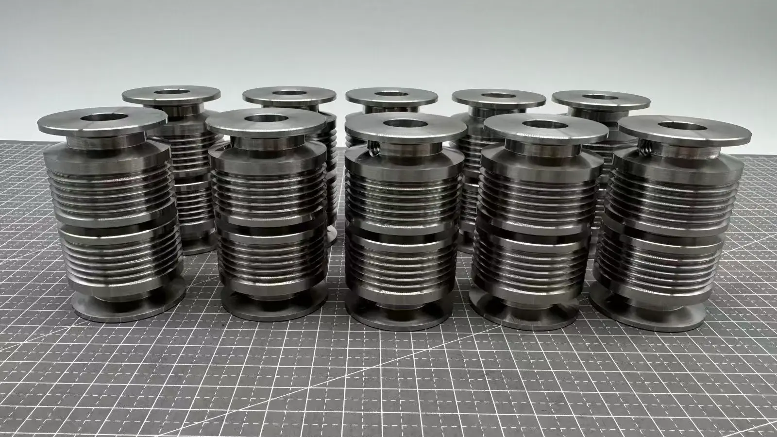
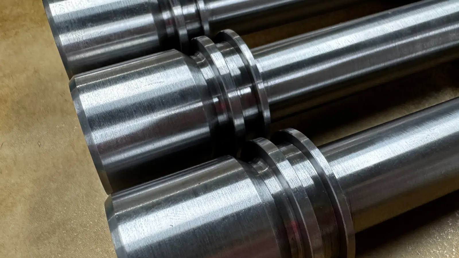
Diameters and Lengths: Rapidly and precisely measures the diameters and lengths of various steps, verifying overall dimensions.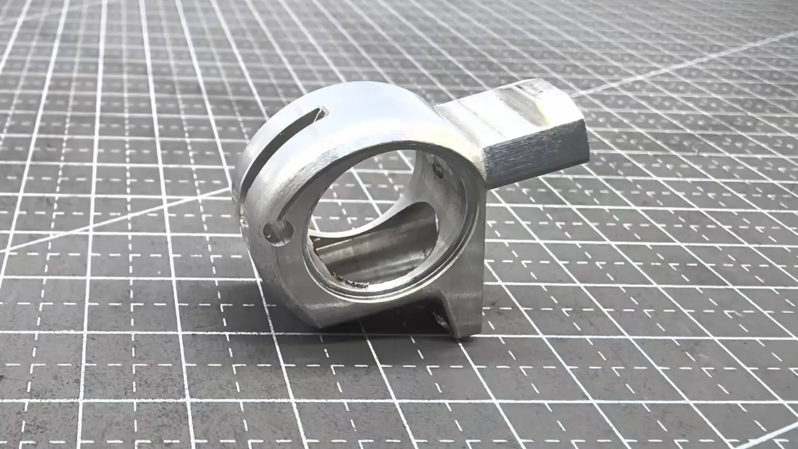
Geometric Tolerances: This is a CMM’s specialty. It accurately evaluates form tolerances (like roundness, cylindricity, straightness, flatness) and position tolerances (like coaxiality, runout, perpendicularity, true position). For example, it verifies if the coaxiality of bearing journals on a main shaft is within tolerance.
Feature Relationships: Measures the orientation of features like keyways, flats, and holes relative to the central axis, checking for symmetry, parallelism, etc.
Housing and Casing Parts include engine blocks, gearbox housings, valve manifolds.
Hole Pattern Position: This is critical for housing parts. The CMM precisely measures the distance between holes and the true position of all mounting holes, bearing bores, and dowel pin holes, ensuring correct assembly with other components.
Depths and Steps: Measures blind hole depths and the step heights between various surfaces.
Threaded Holes: While it cannot directly measure thread pitch diameter, it can verify the location and size of the pilot hole and, used in conjunction with thread gauges, indirectly confirm assembly feasibility.
Measures the profile, twist angle, and leading/trailing edge contours of engine turbine and compressor blades to ensure aerodynamic performance. For integral blisks (bladed disks), the CMM is often the only effective means to inspect their complex internal channels.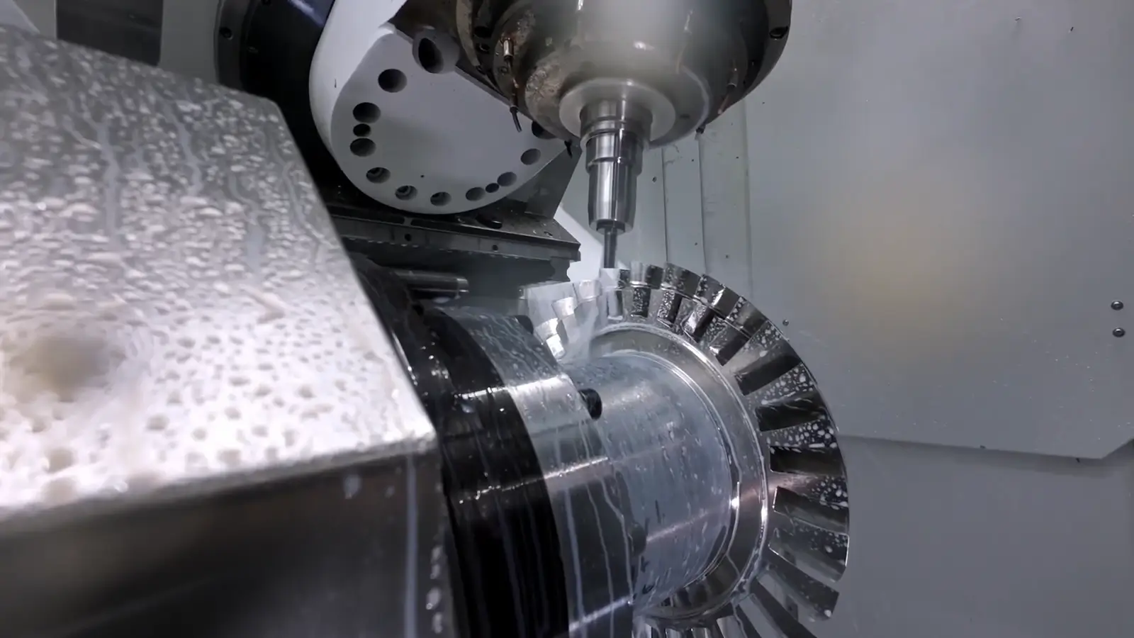
Similar to the precision part verification above, but with even stricter requirements for accuracy and reliability. Inspects all critical dimensions and geometric tolerances of engine blocks, cylinder heads, crankshafts, and camshafts.
Below shows us an example of CMM report.
A Coordinate Measuring Machine (CMM) uses a precision probe to measure part geometry. It captures exact X, Y, and Z coordinates and compares them with the CAD model to ensure dimensional accuracy.
We can inspect a wide range of parts — from small precision components to large mechanical housings, 5-axis machined parts, molds, and complex freeform surfaces.
Our CMMs provide high accuracy, typically within ±0.002 mm, depending on part size, geometry, and measuring conditions.
We can handle parts up to (customize: e.g., 1000 × 800 × 600 mm). Please share your part dimensions, and we’ll confirm compatibility.
Yes. We provide detailed CMM dimensional inspection reports in PDF or Excel format, including GD&T data and deviation analysis.
Yes. Our CAD-based CMM software supports automatic probing paths and freeform surface inspection for 5-axis CNC parts.
We provide CMM reports to almost all our 5 axis CNC parts.
Yes. We can provide FAI reports, PPAP documentation, and other quality certificates based on your project requirements.
Inspection time depends on the part’s size and complexity. Most standard parts can be inspected within 1–2 working days.
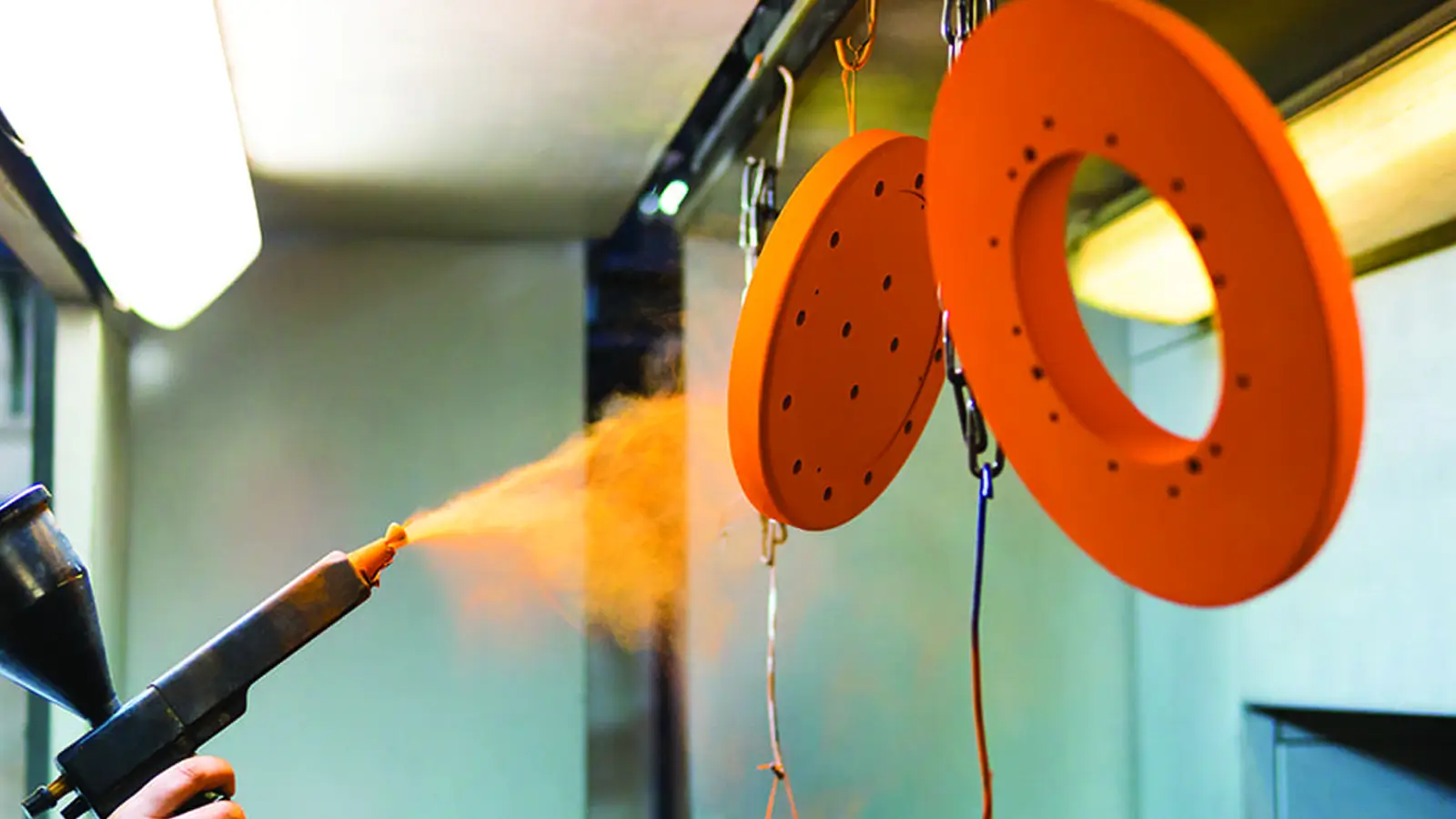
Yes. We can measure post-treatment parts to verify that coating or surface finishing has not affected key dimensions.

5-Axis CNC machining is a manufacturing process that uses computer numerical control systems to operate 5-axis CNC machines capable of moving a cutting tool or a workpiece along five distinct axes simultaneously.

China is the best country for CNC machining service considering cost, precision, logistic and other factors. Statistical data suggests that China emerges as the premier destination for CNC machining.

Selecting the right prototype manufacturing supplier in China is a critical decision that can significantly impact the success of your product development project.

Machining tolerances stand for the precision of manufacturing processes and products. The lower the values of machining tolerances are, the higher the accuracy level would be.