Used in Geometric Dimensioning and Tolerancing(GD&T), feature control frame is an internationally standardized way applied to indicate the specific conditions and tolerances of a geometric control to a particular feature on a part.
On the form, a feature control frame is a rectangular graphic that is divided into certain squares. Used in GD&T on CAD or other engineering drawings, a feature control frame serves as a communication tool to provide details of geometric tolerances and controls for a feature on a part as simple and efficient as possible.
The key information offered by a feature control frame generally includes GD&T symbol, tolerance zone, modifiers and datum references.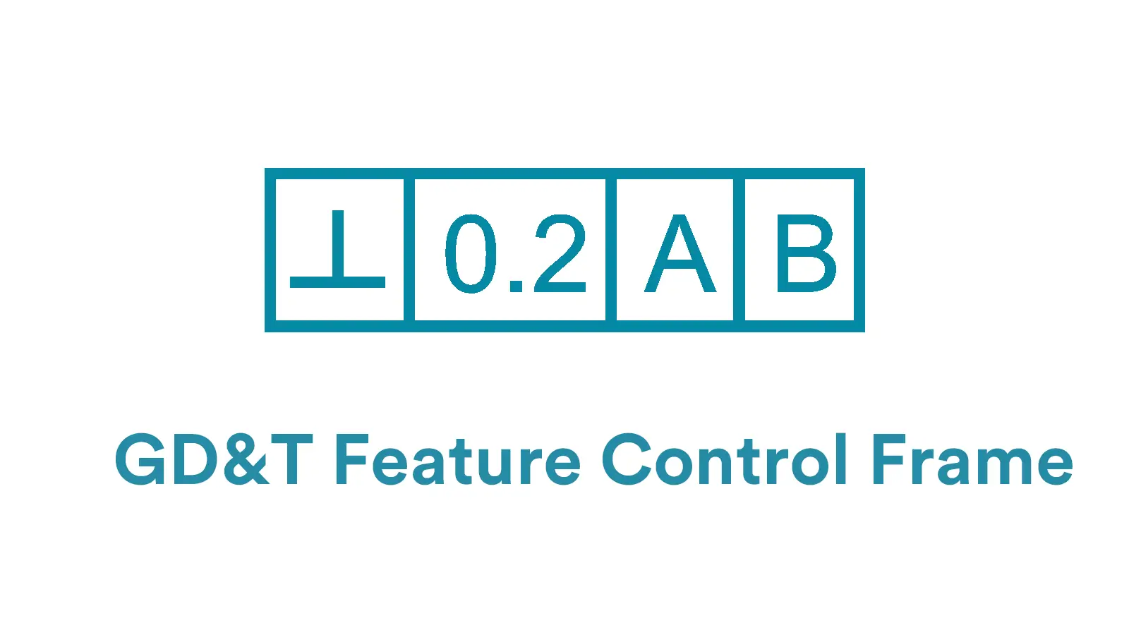
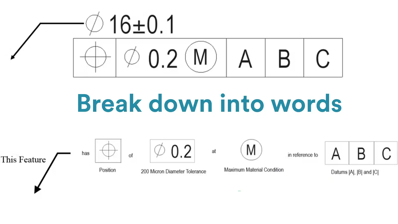
First, identifying the geometric tolerance symbol.
Second, understand the tolerance value and any material condition modifiers (like MMC or LMC).
Third, recognize which datums are referenced.
Together, these elements define how precisely a feature—such as a surface, hole, or axis—must be located or oriented relative to other parts of the component. The position of the frame on the drawing also tells whether the control applies to a size feature or a surface.
Read its feature control frame by a sentence just like the one below.
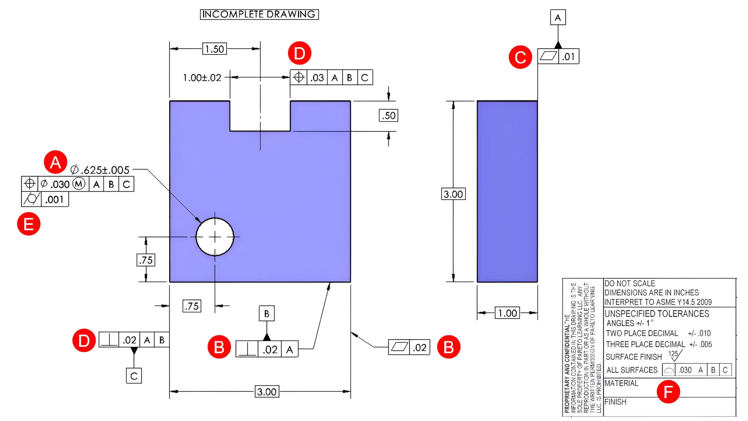
In general, the controlled features can be roughly classified into feature of size(FOS) and surfaces. The particular placement of a feature control frame will determine whether the geometric control is on a feature control size or a surface. The various ways of placing a feature control frame are as follows:
A: The feature control frame is located directly underneath the dimensional indication of the controlled feature, suggesting that the controlled feature is a feature of size.
B: The feature control frame is directly attached to the controlled feature, or the extension line relating to the feature by a leader arrow, suggesting that the controlled feature is a surface.
C: The feature control frame is attached directly to the extension line of the controlled feature, suggesting that the controlled feature is a surface relating to the leader line.
D: The feature control frame is attached to the dimension extension line of the controlled feature. Note that if it is directly in line with the dimensional indication, a feature of size is controlled; but if it is not directly in line with the dimensional indication, a surface is controlled.
E: If the feature control frame is located underneath an existing frame, the controlled feature is same with the existing frame. Such kind of feature control frame is generally used for refinement.
F: The feature control frame is place in a note, chart, or tolerance block where the controlled feature would be clearly indicated by words.
A classic feature control frame commonly covers main information of four aspects:
The detailed explanations for the composition of a feature control frame with a classic example are as follows: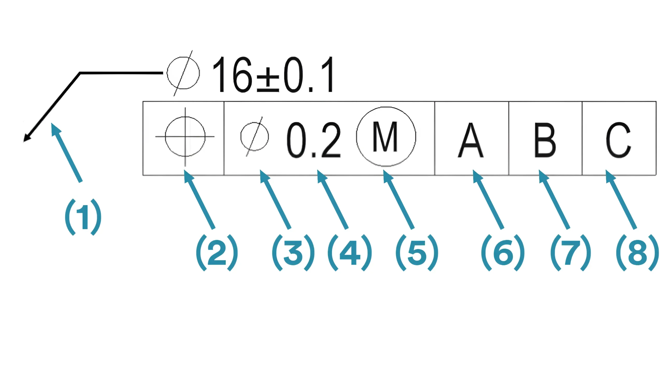
The detailed explanations for the composition of a feature control frame with a classic example are as follows:
(1) Leader Arrow: In GD&T, a leader arrow is generally used to point to the specific feature that the geometric control is placed on. But note that the leader arrow can be chosen to be used or not in engineering
(2) Geometric Symbol: The geometric symbol is the primary element of a feature control frame. A particular geometric symbol refers to the specific geometric control designed for the confined feature of a part.
Main geometric symbols include GD&T Straightness, GD&T Flatness, GD&T Circularity, GD&T Cylindricity, GD&T Parallelism, GD&T Perpendicularity, GD&T Angularity, GD&T Profile of a Line, GD&T Profile of a Surface, GD&T Position, GD&T Concentricity, GD&T Symmetry, GD&T Circular Runout, and GD&T Total Runout, etc. You can click into these articles to learn more information.
(3) Diameter Symbol(if required): Generally, a wide tolerance zone is a default one that does not need to be indicated by a symbol, like the tolerance zone of GD&T Parallelism.
However, if the geometric control is a diametrical tolerance, such as that of the GD&T Cylindricity, then a diameter symbol(Ø) should be shown just before the tolerance value, suggesting that the tolerance value is the diameter value of the tolerance zone.
(4) Tolerance Value: It is the total tolerance(total acceptablevariational zone) of the geometric control. And note that the measuring unit is based on the drawing standard.
(5) Tolerance Modifiers(if acceptable and required): Tolerance modifiers are used to confine the applying condition of the GD&T tolerance Maximum Material Condition(MMC) and Least Material Condition(LMC) are two most common modifiers in GD&T. For further clarification and understanding, seethem in the GD&T Symbols Page.
(6) Primary Datum(if required): If a datum is required for the geometric control, it is the upmost datum feature referred by the controlled feature, and must be constrained first during measurement. The capital letter “A”is used to indicate a primary datum.
What’s more, the letter in a feature control frame corresponds to the datum feature somewhere on the part which will be marked with the same letter on the engineering
(7) Secondary Datum(if required): If a secondary datum is needed for reference, it will be indicated at the right of the primary datum symbol. The capital letter “B”is used to indicate a secondary datum.
Same with the primary datum, the letter in a feature control frame corresponds to a datum feature somewhere on the part which will be marked with the same letter on the engineering drawing. And it is fixated after the primary datum during measurement.
(8) Tertiary Datum(if required): If a tertiary datum is needed for reference, it will be indicated right after the secondary datum symbol in a feature control frame. The capital letter “C”is used to indicate a tertiary.
The letter corresponds to a specific datum feature on the part which will be marked with the same letter on the engineering drawing. And it is fixated last during measurement. Note that the order of the datums should be considered critically during measurement.
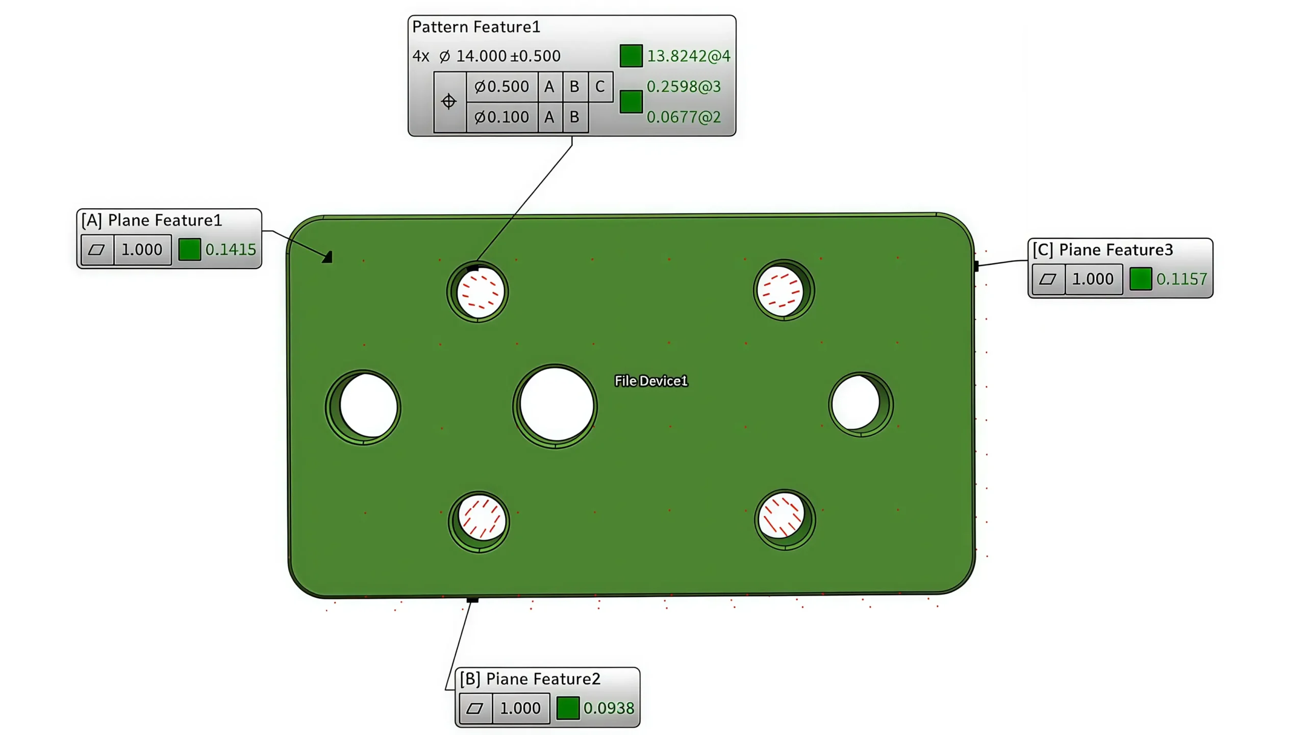
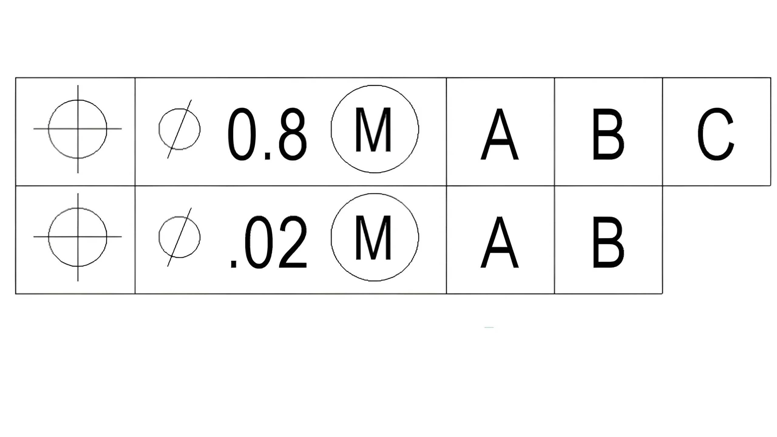
A Composite Feature Control Frame contains two tolerance zone frameworks that share a single geometric symbol.
It is usually applied to the situation where the relationship among each feature must be kept to a certain tight tolerance and that between the pattern and its datum features is not so much critical and may be held to a looser tolerance.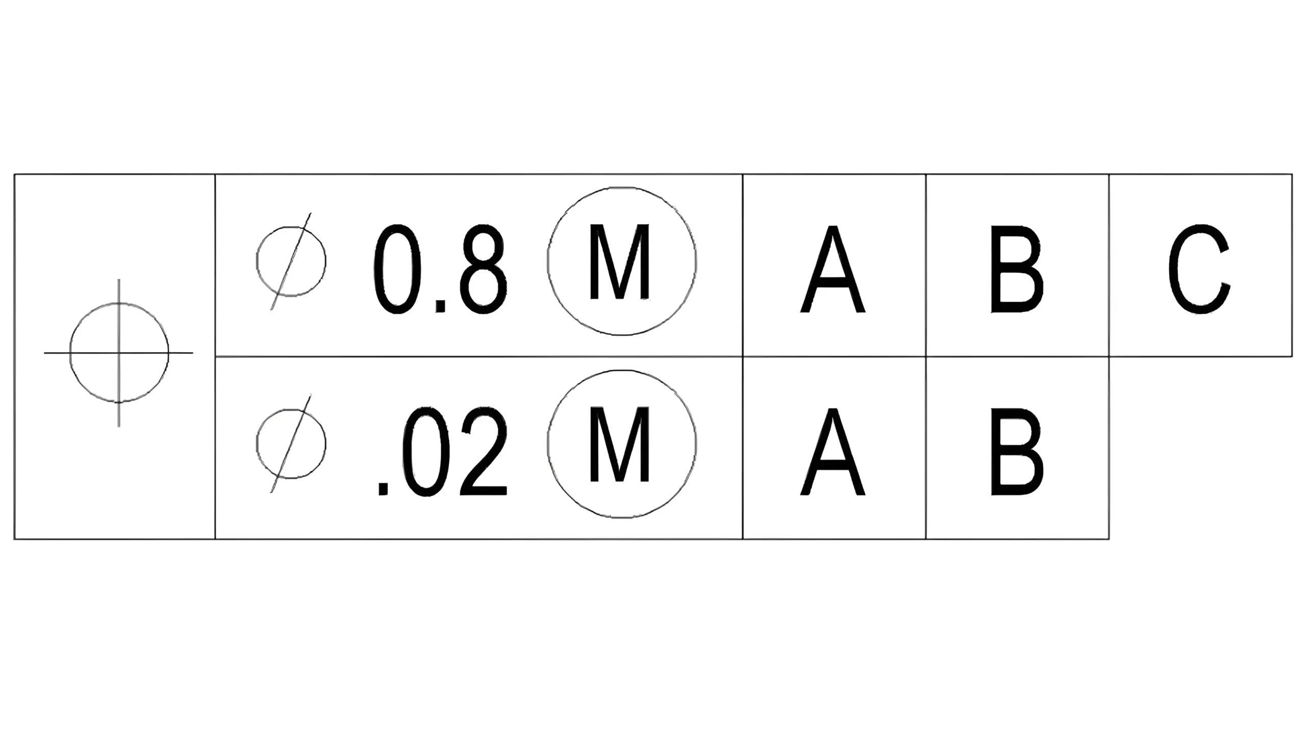
The top frame is the pattern-locating control, which establishes the Pattern Locating Tolerance Zone Framework(PLTZF), pronounced “plahtz”.
It controls the relationship between the pattern and datum reference frame. In short, it functions same as any other normal position tolerance.
The bottom frame is the feature-relating control, which establishes the Feature Relating Tolerance Zone Framework(FRTZF), pronounced “fritz”. It is used to refine the orientation of the pattern itself, governing the relationship from feature-to-feature.
A composite feature control frame must align the following rules:
The most common kind of composite feature control frame is the one with only primary datum in the bottom frame, just like the above example.
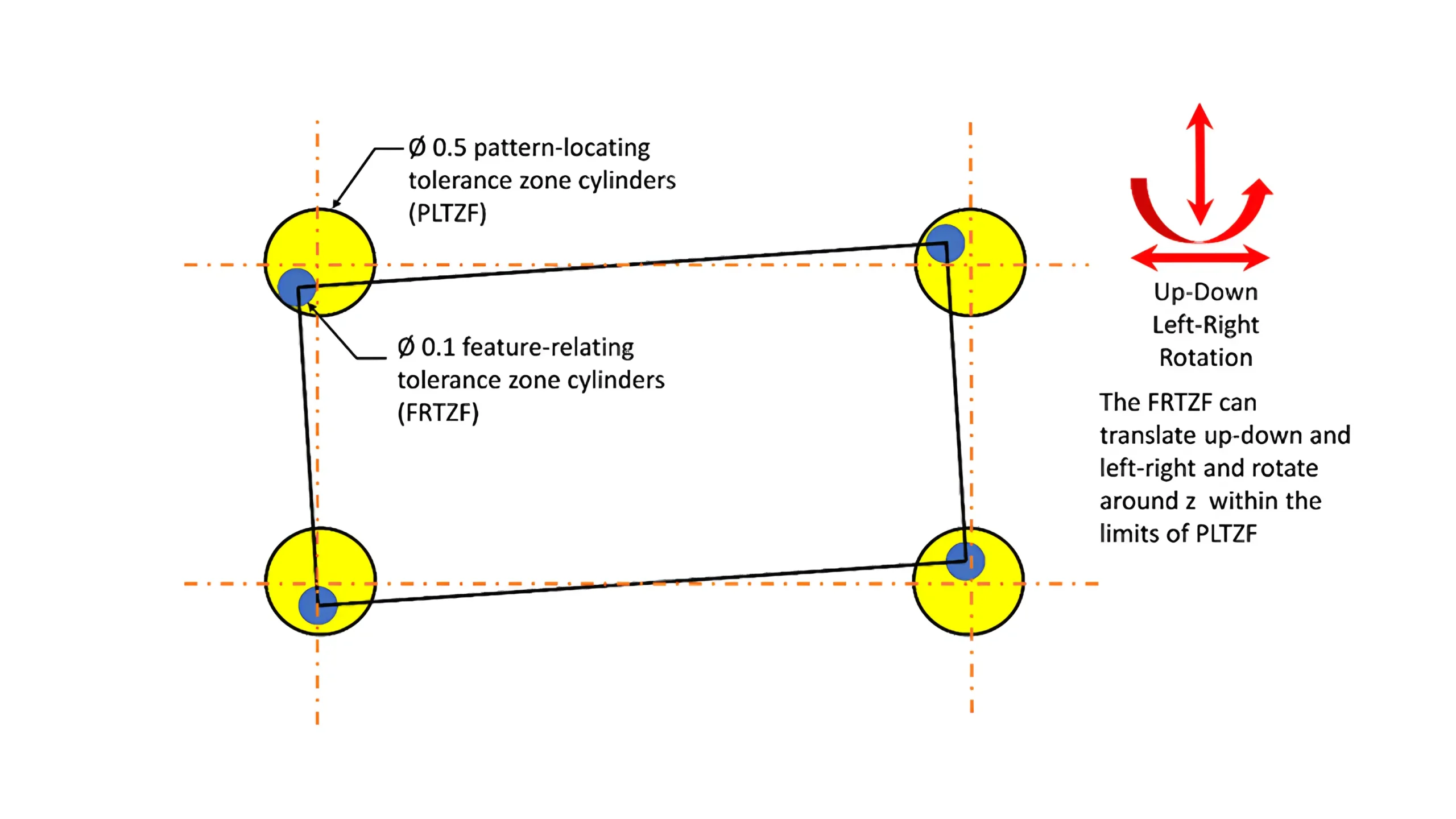
In the above example, the yellow tolerance zones refer to the PLTZF and the bule tolerance zones refer to the FRTZF.
The former constrains the location and orientation of the pattern relative to datum ABC, whereas the latter constrains the location and orientation of individual holes within the pattern, and the orientation only relative to datum A.
Controlled by this composite feature control frame, the axes of these holes must reside within the overlapped tolerance zones of PLTZF and FRTZF.
And they must keep perpendicular to the datum A feature, but can translate and rotate with respect to datum B or C freely.
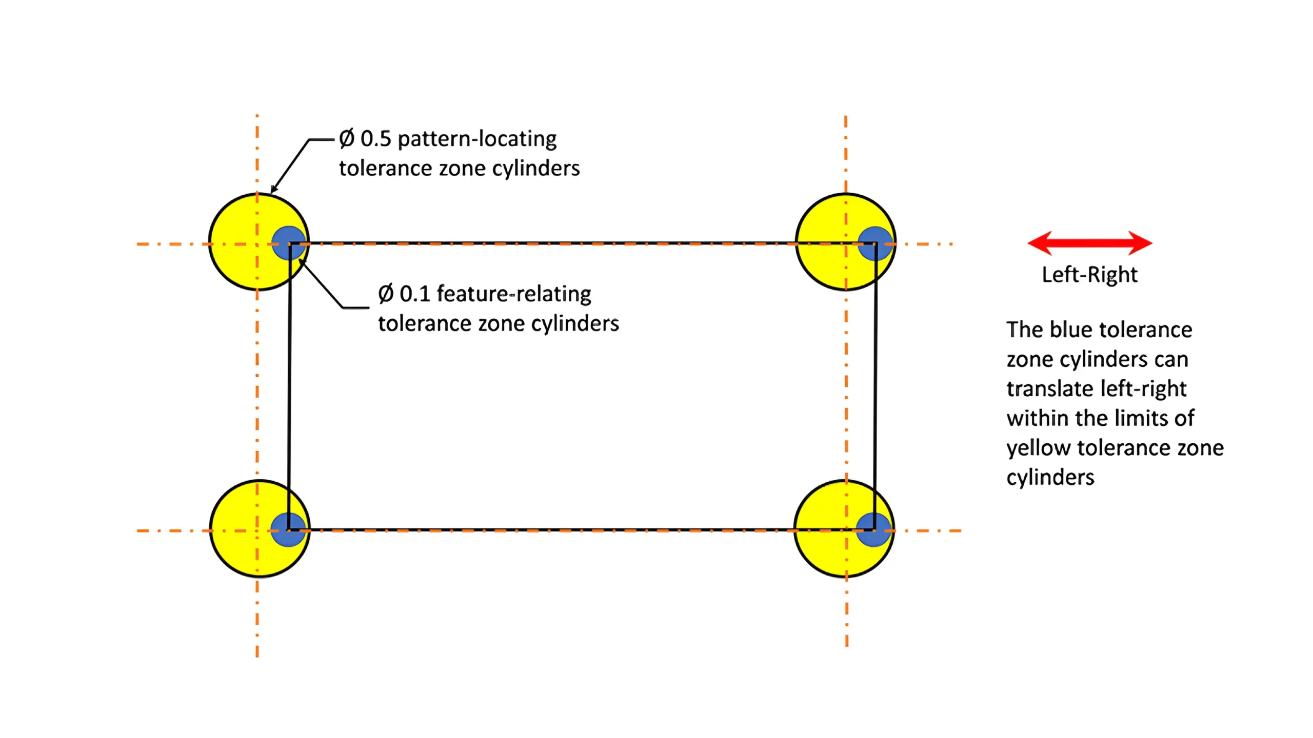
This kind of composite feature control frame is the one with primary and secondary datum in the bottom frame.
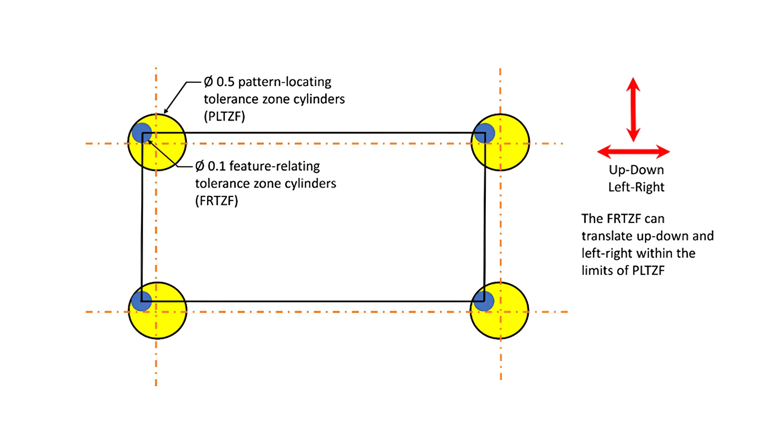
Same with the example 1, the yellow tolerance zones are the PLTZF that constrains the location and orientation relative to datum ABC, and the bule tolerance zones are the FRTZF that confines the location and orientation of individual hole within the pattern.
The difference is that the FRTZF of the example 2 constrains the orientation relative to datum A and B.
Controlled by this kind of composite feature control frame, the axes of these holes must lie within the overlapped tolerance zones of PLTZF and FRTZF.
And they must stay perpendicular with the datum A feature. Since the bottom frame is applied to control the orientation but not the location with respect to the datum A and B, the FRTZF can move up and down, and left and right freely within the limits of PLTZF.
Compared with the example 1, the rotation is not allowed.
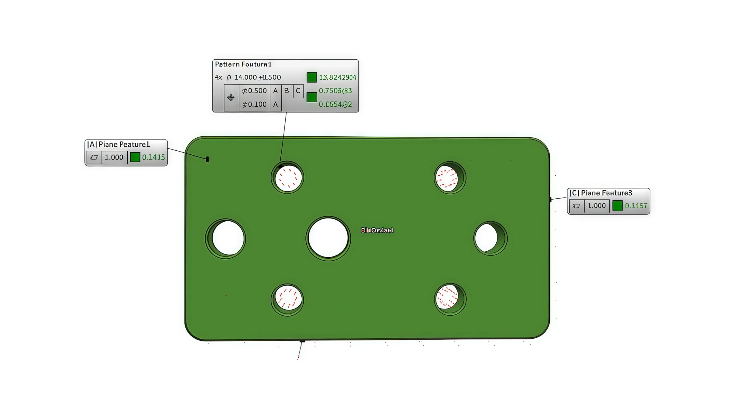
Same as a composite feature control frame, a multiple single segment feature control frame also contains two tolerance zone frameworks.
The difference is that the two subsets of frame within a multiple single segment feature control frame are completely independent to each other.
Each of them has their own position symbol, but not share the same one as in a composite feature control frame.
The top frame of a multiple single segment feature control frame functions totally similar to that of a composite feature control frame. The key difference lies on the bottom frame.
The bottom frame of a multiple single segment feature control frame constrains both the orientation and location of the holes relative to the datums.
However, the bottom frame of a composite feature control frame can only constrain the orientation of the holes relative to the datums, and the relative location of the holes themselves.
More importantly, since the two frames of a multiple single segment feature control frame are independent to each other, the bottom frame of it can call out any datum in any order.
But note that an exact copy of the top datum frame is not allowed, this would lead to a result that the bottom frame would wipe out the requirement in the top frame altogether since the bottom frame has a tighter tolerance.
A multiple single segment feature control frame must align the following rules:
Unlike a composite feature control frame, both the two segments of a multiple single segment feature control frame are used to control the location and the orientation relative to the datums.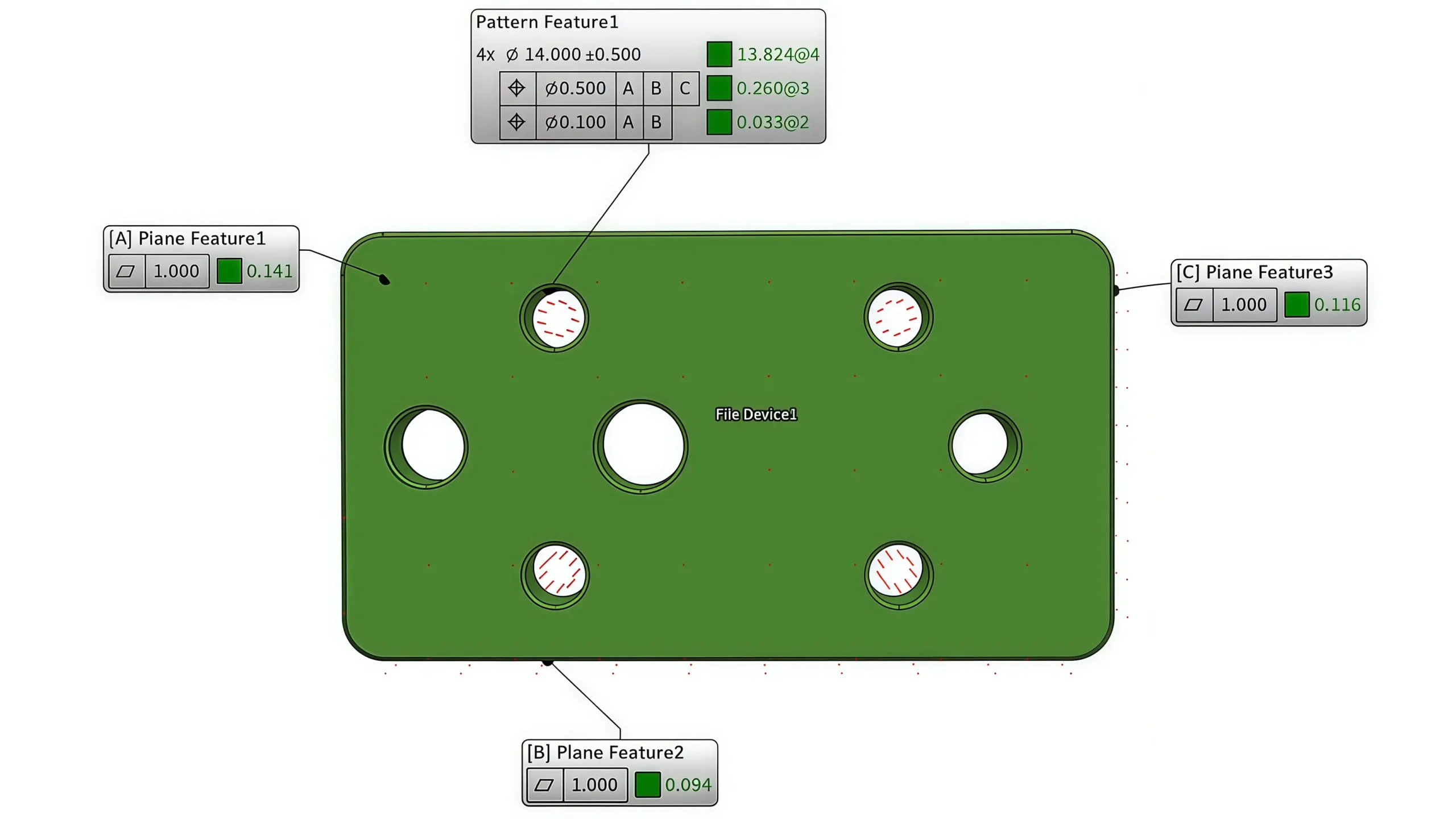
The yellow tolerance zones above refer to the top frame, constraining the location and orientation relative to datum ABC. While the bule tolerance zones refer to the bottom frame, constraining the location and orientation relative to datum A and B.
The axes of these holes must lie within the overlapped zones of both the two frames, and they must be perpendicular to datum A feature.
More importantly, since the location relative to datum B is also constrained by the bottom frame, the blue zones can only move right and left within the limits of the yellow zones.

5-Axis CNC machining is a manufacturing process that uses computer numerical control systems to operate 5-axis CNC machines capable of moving a cutting tool or a workpiece along five distinct axes simultaneously.

China is the best country for CNC machining service considering cost, precision, logistic and other factors. Statistical data suggests that China emerges as the premier destination for CNC machining.

Selecting the right prototype manufacturing supplier in China is a critical decision that can significantly impact the success of your product development project.

Machining tolerances stand for the precision of manufacturing processes and products. The lower the values of machining tolerances are, the higher the accuracy level would be.