Generally, the tolerance requirements would be indicated on the bottom right of 2D in CNC machining. ISO 2768-mK is often applied in CNC machining as standard tolerance or typical tolerance.
Below is a standard 2D drawing from ECOREPRAP, on which you can see that ISO 2768-mK is our standard CNC machining tolerance.

Following are several pictures showing drawing specifications from clients of different countries. Some clients use ISO 2768-mK or ISO 2768 V to indicate their wishing tolerances.
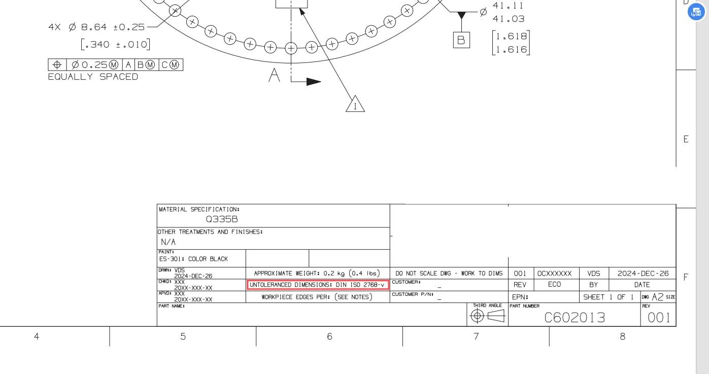


The main reason is that designers, programmers and manufacturers can catch the tolerances indicated clearly on 2D drawings through decimal places quickly.
Some operators do not know what ISO 2768 is specifically, but they can interpret the tolerances indicated through decimal places easily. While there is still one thing to be stated: ISO 2768 can be in mm and inch.
Learn more about other standards of CNC machining tolerances.
Yes, it offers four main classes that control the precision of linear dimensions, angles, and general form/location (like flatness): fine, medium, coarse, and very coarse.
Our Recommendation: If you don’t specify anything, we typically default to the (Medium) class, as it offers the best balance of cost and quality for general parts.
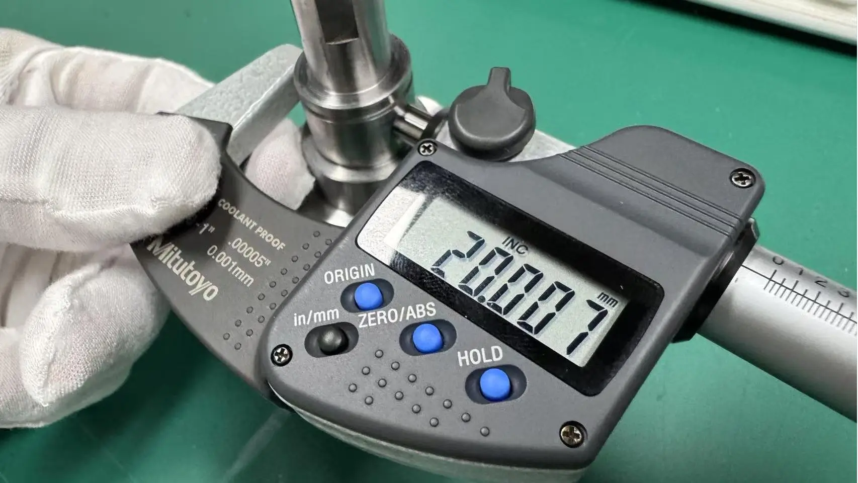
If a certain dimension (like a bore for a bearing or a key fit) needs a tolerance tighter than what provides (e.g., 0.02mm), you must call out that specific tolerance value directly on the drawing.
: Primarily controls size (length, width, diameter) and angular deviations. It deals with the part’s general dimensional accuracy.
: Uses specific symbols to control the part’s form, orientation, and location (e.g., flatness, perpendicularity, position). It deals with the part’s geometric functional accuracy.
ISO 2768 is divided into two parts:
ISO 2768-1: General tolerances for linear and angular dimensions
ISO 2768-2: General tolerances for geometrical features, including flatness, straightness, and circularity
Yes. ISO 2768 can be used in millimeters (mm) or inches (inch) depending on the drawing specification or industry standards.
Absolutely not. ISO 2768 is a “default” or “fallback” standard. You can specify “ISO 2768-mK” on the drawing as a general tolerance, while simultaneously specifying tighter tolerances individually for those critical fitting or functional dimensions. Manufacturers will prioritize the individually specified dimensions.
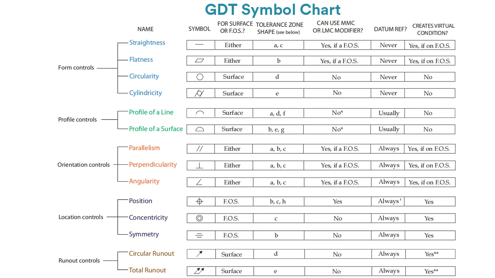
GD&T (Geometric Dimensioning and Tolerancing) is an internationally standardized engineering language, following standards such as ASME Y14.5 or ISO 1101.
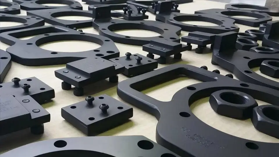
Machining tolerance is the acceptable value scope of deviation from the original designed feature dimensions indicated on drawings.

Selecting the right prototype manufacturing supplier in China is a critical decision that can significantly impact the success of your product development project.

Machining tolerances stand for the precision of manufacturing processes and products. The lower the values of machining tolerances are, the higher the accuracy level would be.