Least material condition functions as one of the material modifiers in GD&T to ensure the effective functions of parts when least material is used. Although least material condition is not used as commonly as maximum material condition, it is still important to know about it comprehensively.
GD&T least material condition is a feature of size symbol which refers to the dimensional condition where the particular feature contains the least amount of material within its indicated tolerance.
For concrete examples:
For an internal feature like a hole, LMC=Largest size of the hole
For an external feature like a pin, LMC=Smallest size of the pin
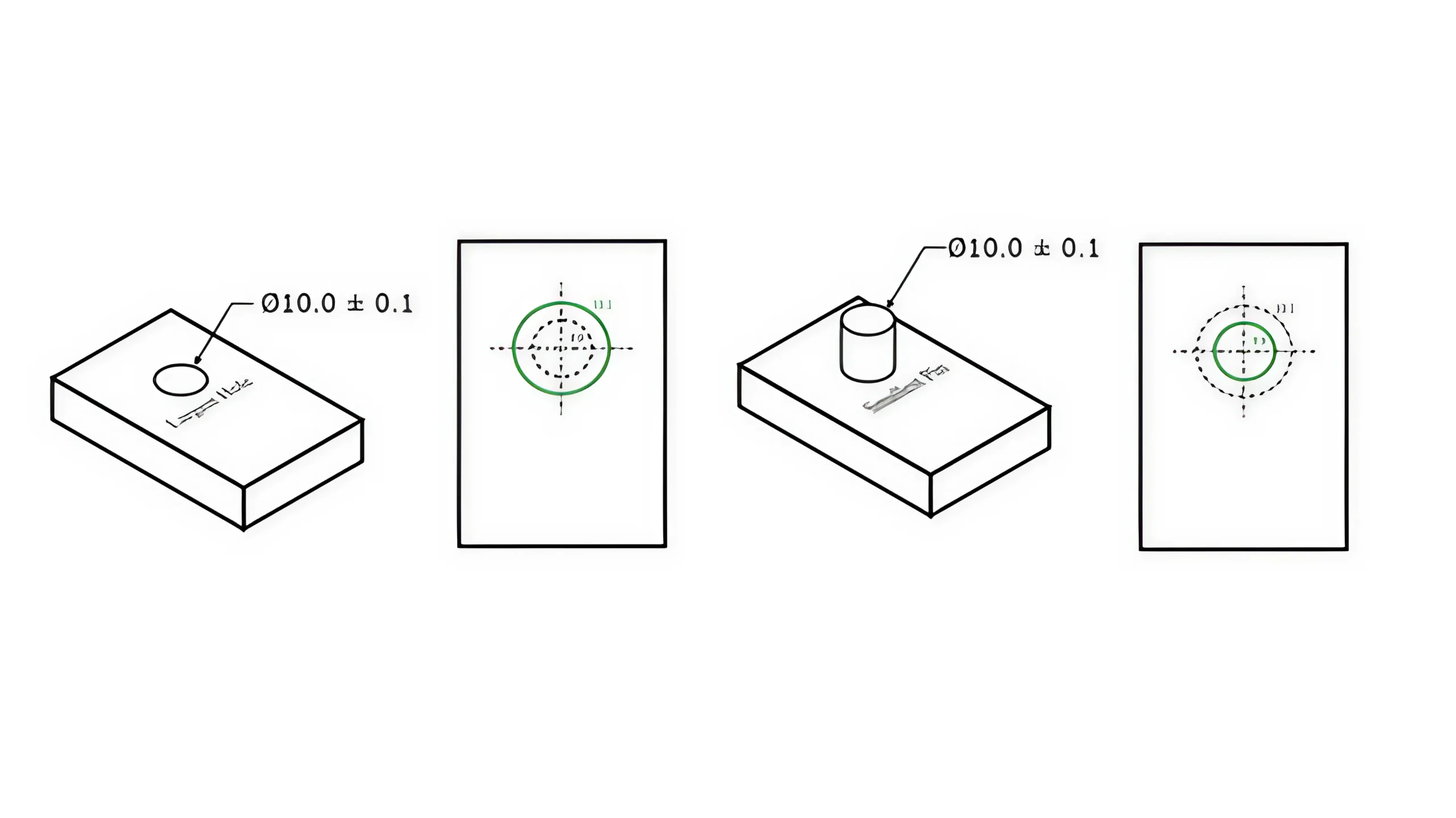
In short, least material condition(LMC) is one end of the part’s dimensional range. And the other one is the maximum material condition.
In a feature control frame, if required, it would be indicated just after the tolerance value as L, which is the least material condition symbol.
LMC is used when it is critical to control the minimum material thickness, especially near edges, or to manage the position of features where the worst-case situation is when the feature is at its LMC.
The most common applicated situation of LMC is when there is a hole or other internal feature that is very close to the edge of a part.
Take the following figure for example.
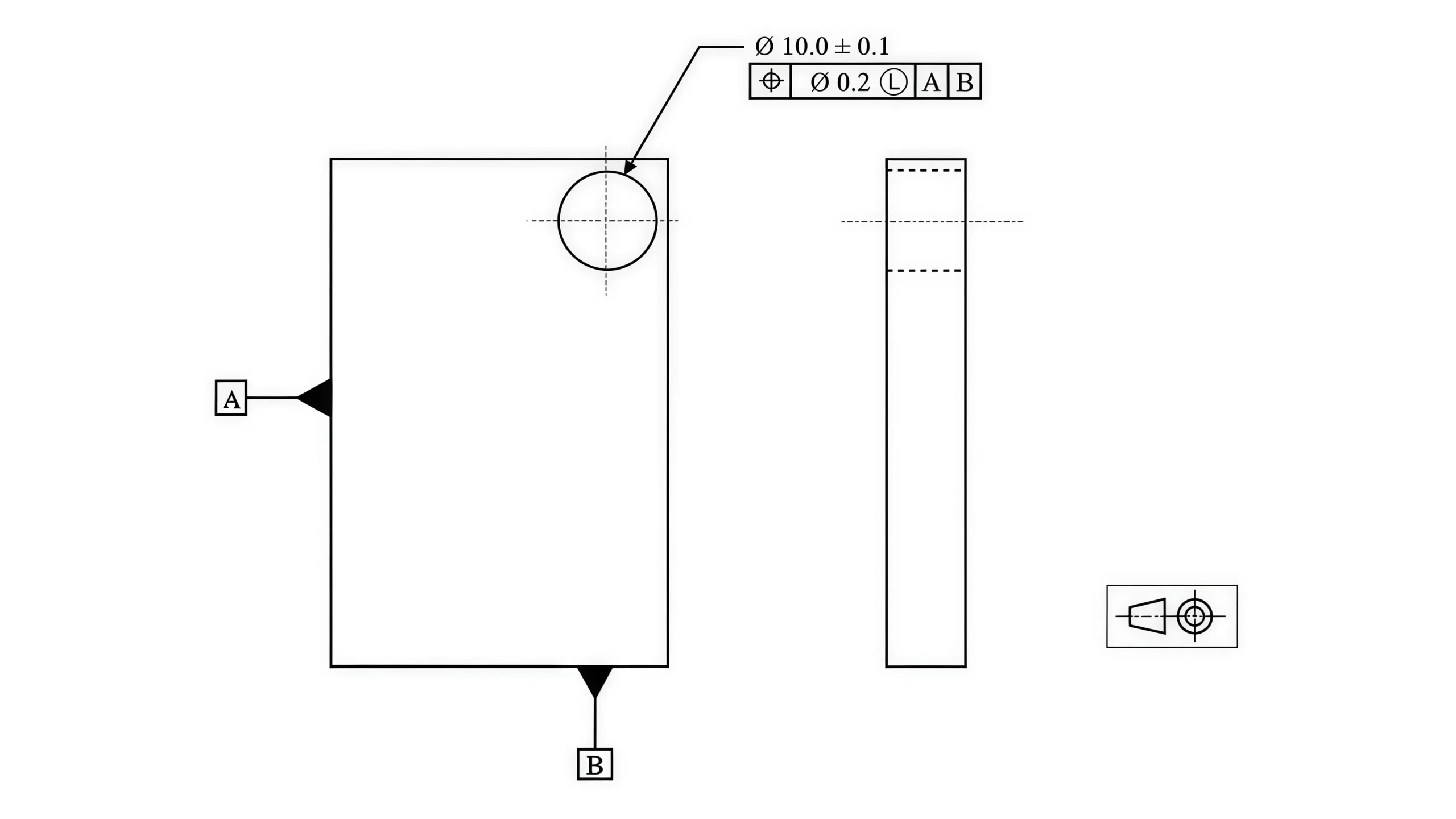
In this figure the LMC is called out with true position. It is known that when the hole is at its largest size(LMC), it can only vary by as much as the true position tolerance(0.2).
But if the hole deviates from its Least Material Condition, its exact position can be added with a bonus tolerance, because now the true center of the hole can get closer to the edge without reducing the thickness of the material.
LMC defines that the allowable geometric tolerance can increase when the actual dimension of the feature deviates from its LMC towards its MMC.
For LMC of a hole, Bonus Tolerance=LMC-Actual Dimension
For LMC of a pin, Bonus Tolerance=Actual Dimension-LMC
In fact, LMC is rarely used in GD&T to some extent. But it still has important functions in certain aspects.
Ensuring Mating Function: It is one of themost essential functions of LMC, which ensures the part can still assemble or perform as required under the worst-case material condition. If the LMC of a shaft is made sure to always be larger than the LMC of a hole, there will always be a tight fit between the parts.
Providing Bonus Tolerance: LMC defines that when the actual dimension of the feature deviates from its LMC towards MMC, the allowable geometric tolerancewould increase as much as the deviation, which can effectively elevate the passing rate.
Controlling the Thickness of Material: For thin-walled parts or high-stress areas, LMC ensures sufficientstrength even when the least material is contained. For instant, for the cooling channels in an engine block, we should ensure that the minimum wall thickness would still be strong enough to prevent cracking.
Controlling Designing Room: In compact assemblies, LMC can prevent parts from interfering with adjacent structures due to insufficient material. For instant, LMC can ensure that the PCB mounting holes on electronic devices maintain safe clearance with the housings even at maximum hole size.
Balancing Cost and Quality: Compared with MMC, LMC is more suitable for material-saving and lightweight designs. If the material is expensive, the applicationof LMC can reduce the cost of material and meanwhile ensure the quality of the parts.
No-Go Gauges are a kind of specific functional gauges that can be used to control the Least Material Condition of features. As we have explained above, if you want to ensure a proper fit by limiting the feature’s dimension, you can specify the LMC callout of the feature and control it with a No-Go Gauge.
For instant, if you want to ensure that a pin would always have a tight fit with a hole, you can design a No-Go hole gauge to simulate the least material condition of the pin. The No-Go Guage would be a block with a hole whose diameter is equal to the pin’s LMC(the pin’s minimum diameter).
And then you can try to insert the pin into the hole in order to check if the part is up to standard. If the pin does not fit into the hole(No-Go), then it has been checked that the pin is large enough to be a tight press into the feature.
Note: A No-Go Gauge for a hole would be a pin gauge whose diameter is equal to the hole’s maximum diameter.(Gauge’s Ø=Hole’s Max Ø)
A No-Go Gauge for a pin would be a hole gauge whose diameter is equal to the pin’s minimum diameter.(Gauge’s Ø=Pin’s Min Ø)
The chief drawback of Least Material Condition is that it can not be measured with geometric tolerance at once by a functional gauge as Maximum Material Condition does.
For example, if there is a hole whose position tolerance is controlled with LMC, you have to measure the position and least material condition separately, instead measuring them at once by a functional gauge.
You can check the hole’s size with a No-Go Gauge to ensure that it is small enough for a press fit, but you cannot use the gauge to check the position too. GD&T tolerances should be measured through other means like CMMs and so on.
The essential reason is that the No-Go Gauge passes the Least Material Condition by holding the feature back.
For instant, if a hole is smaller than its LMC, it can not go through the No-Go Gauge(a pin with diameter slightly larger than the feature’s LMC size), then the feature passes. But if it passes the gauge, the feature’s size can be confirmed beyond the allowable dimension zone.
It means that any holes whose dimeter is smaller than its LMC size can not pass through the No-Go Gauge, and the position or other GD&T tolerance can not be measured.
Although Least Material Condition is not used as much usually as other material modifiers, it still plays a significant role in CNC machining and other manufacturing. Therefore, it is important to have a good gris of grasp of Least Material Condition. If you have any confusion, contact with us directly.
There are three material modifiers in Geometric Dimensioning and Tolerancing, including Least Material Condition, Maximum Material Condition, and Regardless of Feature Size. They are all used to specify the condition that the feature must be in to apply the specified tolerance.
The Least Material Condition and Maximum Material Condition would be indicated on drawings as L and M respectively. However, Regardless of Feature Size is the default condition; it would not be indicated on drawings. It means that the geometric controls exist regardless of how large or small the part dimensions are.
Lucas is a technical writer at ECOREPRAP. He has eight years of CNC programming and operating experience, including five-axis programming. He also spent three years in CNC engineering, quoting, design, and project management. Lucas holds an associate degree in mold design and has self-taught knowledge in materials science. He’s a lifelong learner who loves sharing his expertise.
Copyright © 2025 Shenzhen ECO Industrial Co.,Ltd. All rights reserved.