In our previous blog, we explored two key concepts in CNC machining: fillets and chamfers. Today, we’re shifting our focus to another fundamental idea—the Undercut.
This article will guide you through its fundamental principles, common types, and practical applications, providing a clearer understanding of how it works and why it matters. This is a complete guide for undercut in CNC machining.
Key Takeaways:
An Undercut is an important and often critical geometric feature in machining and manufacturing. An undercut refers to a recessed or inward-facing shape on a part that directly influences how the part is machined, molded, and ultimately, how it functions.
Broadly speaking, an undercut is any kind of groove or recess that can’t be easily produced using standard tools or straightforward linear motions.
The core idea is simple: it’s a feature that’s “hidden” or blocked by another part of the component itself.
Think of it as a “hard-to-reach” area or an inward-turning structure that ordinary cutting tools can’t access directly.
In CNC milling or turning, an undercut usually means a hidden geometry – where part of the workpiece is shadowed by an overhanging feature (like a shoulder or boss), making it impossible for a standard vertical tool to reach.
A special machining tool is needed to make the undercut – which calls for non-standard cutters, such as:
Common examples include thread relief grooves, T-slots, dovetail slides, and O-ring grooves.
In molding processes—like injection molding, die casting, or casting—the term undercut takes on an even more critical role:
It’s any feature that prevents the finished part from being cleanly ejected straight out of the mold.
If an undercut is present, the mold must include additional moving components; otherwise, the part will get stuck.
Common mold solutions (which add complexity and cost):
Slides – side-acting mold parts that move horizontally to clear the undercut before ejection.
Lifters – components that move at an angle during ejection to release undercut features.
Insert molds – removable sections of the mold.
Whether in CNC machining or in molding, an undercut fundamentally refers to a hidden or recessed geometry that can’t be made—or released—using standard straight-line motions or tools.
That’s why undercuts often increase cost and complexity: they demand special tooling, advanced programming, and sometimes, more elaborate mold designs.
Still, they’re often intentionally designed by engineers to serve essential functions—like allowing threads to run fully, enabling secure snap-fits, ensuring tight seals, or creating strong mechanical connections.
Designers don’t include undercuts to make manufacturing difficult—they do it to enable critical functions that make the final product work better. Let’s explore the main reasons you’ll find undercuts in a design.
This is the most common and vital purpose of an undercut. By removing material in specific areas, we can guarantee that parts fit together seamlessly and function as intended.
Undercuts can form clever, self-locking mechanisms that reduce or even eliminate the need for extra screws or fasteners.
In high-performance industries, undercuts are used to fine-tune a part’s physical properties.
Sometimes, an undercut isn’t for the final product’s function, but for the machining process itself.
Here at ECOREPRAP, we specialize in prototyping and small-batch manufacturing. That’s why we’ll focus on the types of undercuts you’re most likely to encounter in CNC machining.
In the world of CNC, an undercut is a recessed feature that requires a special tool to mill or turn. They’re not just for show—each type serves a clear purpose for function and assembly. Let’s break down the most common ones.
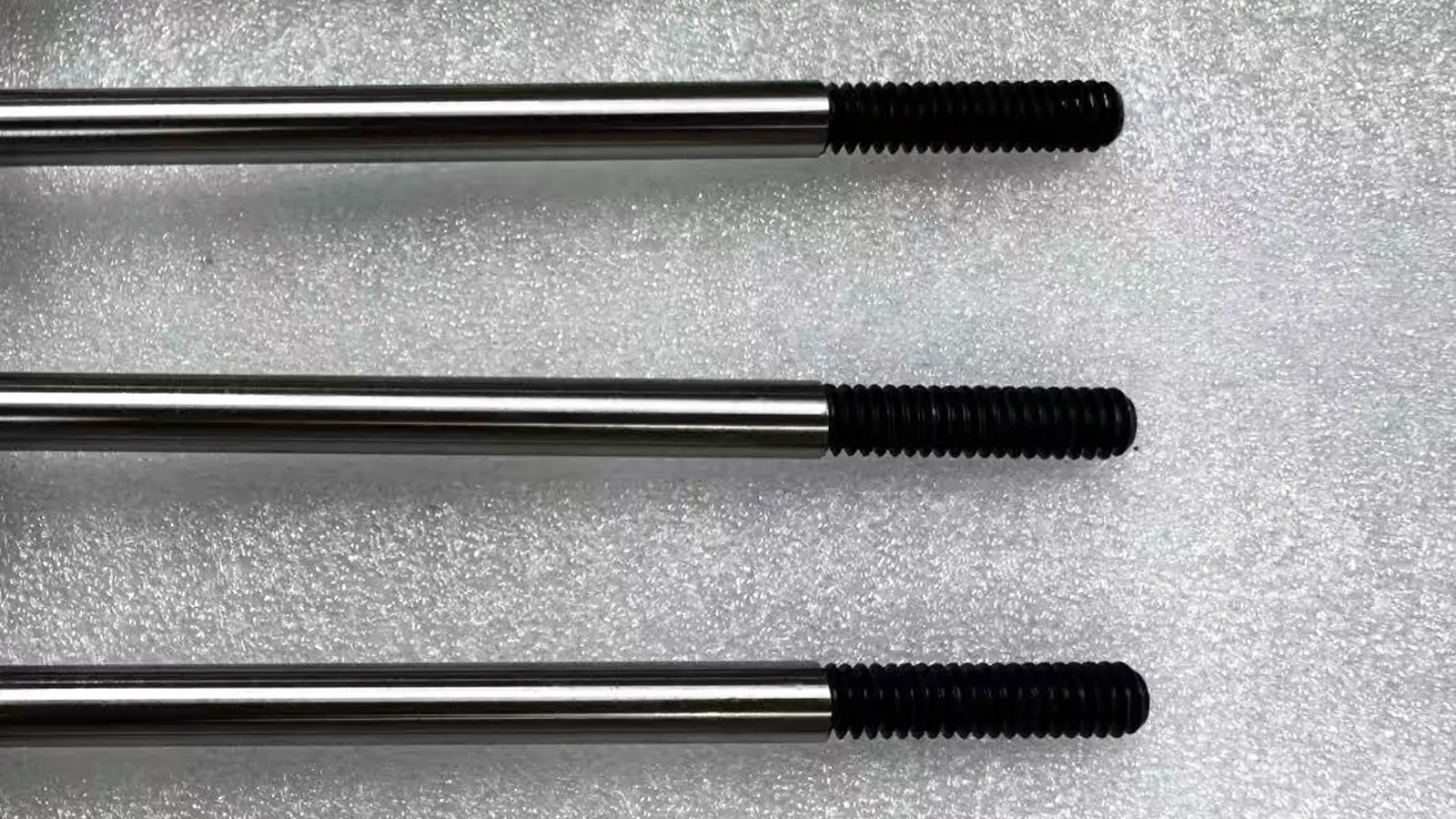
The Thread Relief Groove is a small, ring-shaped groove cut at the end of a threaded section on a shaft or inside a hole, right before a vertical shoulder.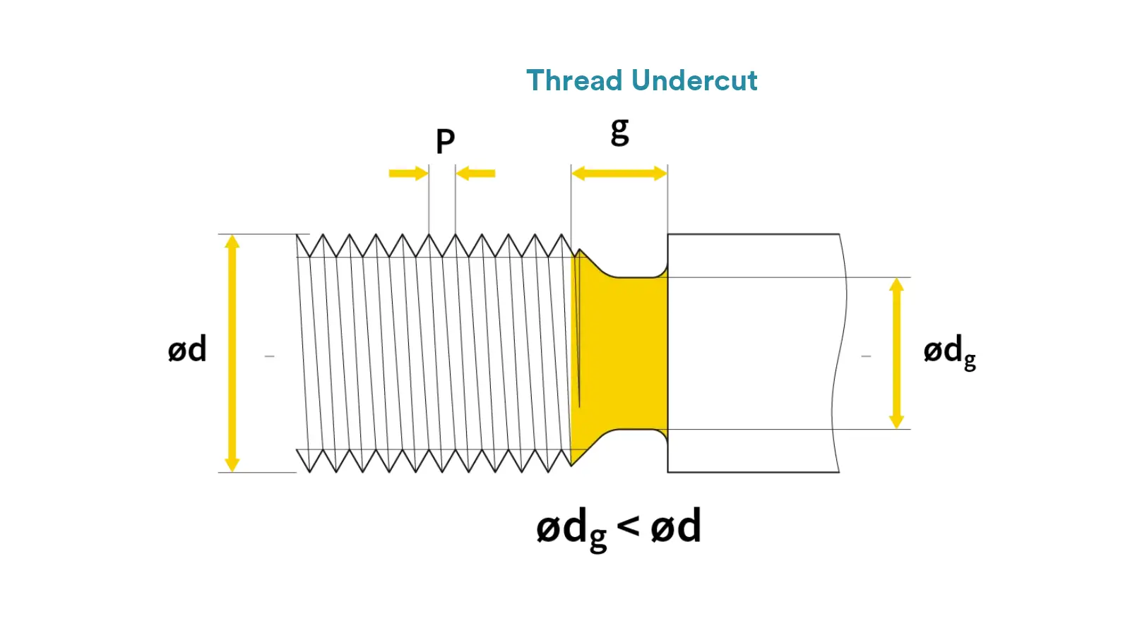
This groove gives the threading tool a clean space to exit, preventing messy threads and burrs. More importantly, it allows a nut to screw down completely, seating flush against the shoulder for a tight, precise fit. It’s all about ensuring a perfect assembly.
The T-Slot is a slot with a T-shaped cross-section. The bottom of the slot is wider than its top opening, creating an overhang.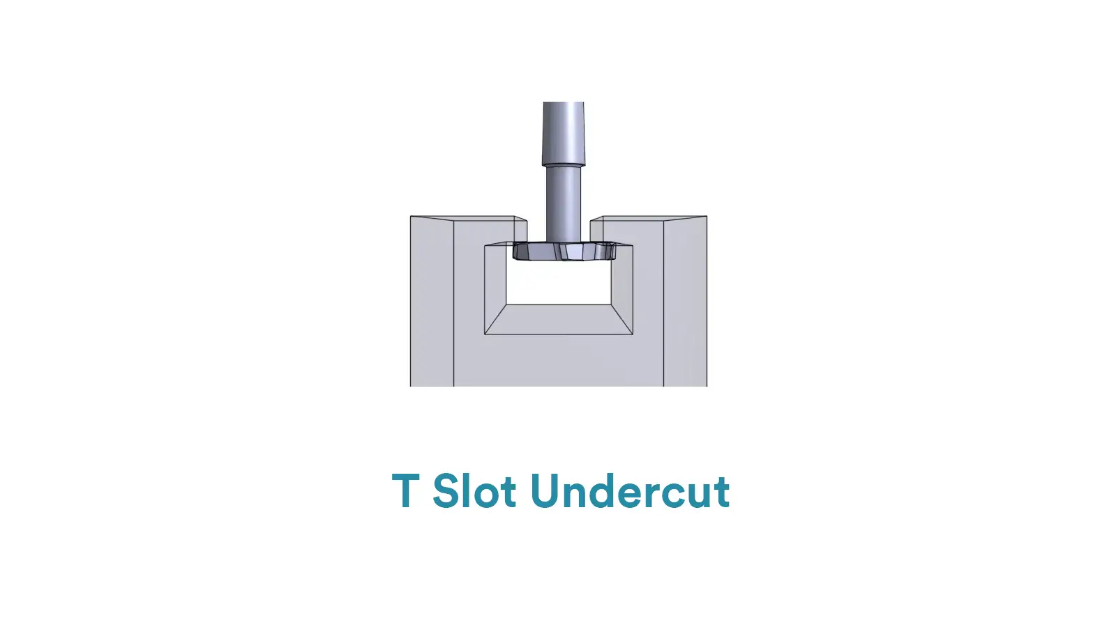
T-slots are the ultimate solution for modular fixturing. They are machined using a special T-slot cutter and allow T-bolts to be slid in and locked down anywhere along the length of a machine table or frame. This provides incredibly strong and adjustable clamping.
The Dovetail Slot is a slot with a trapezoidal shape, where the walls are cut at an angle, making the top opening narrower than the bottom.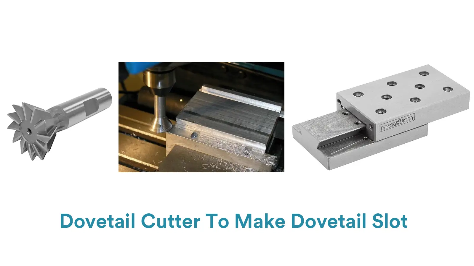
Dovetails create a precise, self-locking sliding connection. Machined with a specialized dovetail cutter, they are famous for use in machine tool slides and guides. The angled walls prevent the mating part from lifting out, ensuring rigid and accurate linear movement.
The Shoulder Relief Groove is a very small and shallow groove cut into the inner corner where a shaft’s diameter changes (at a shoulder).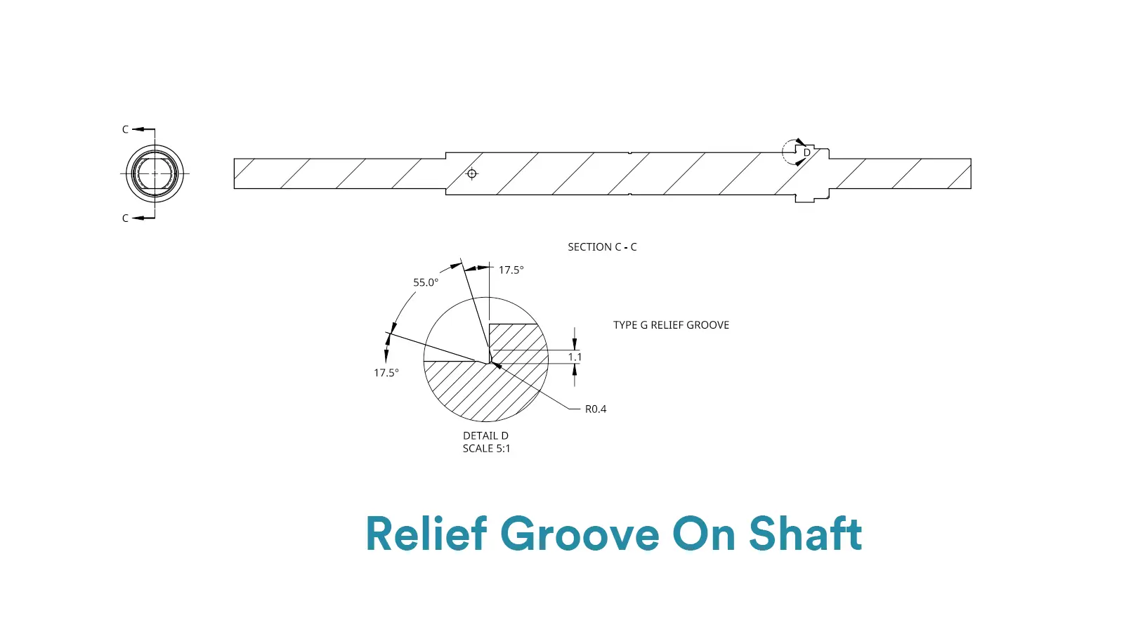
This tiny groove solves a big problem. It provides clearance for the corner of a mating part (like a bearing or gear), ensuring its face sits perfectly flat against the shaft’s shoulder. It also helps reduce stress concentration in that corner, making the part stronger.
The O-Ring Groove is a precisely sized ring-shaped groove designed to hold an O-ring or gasket.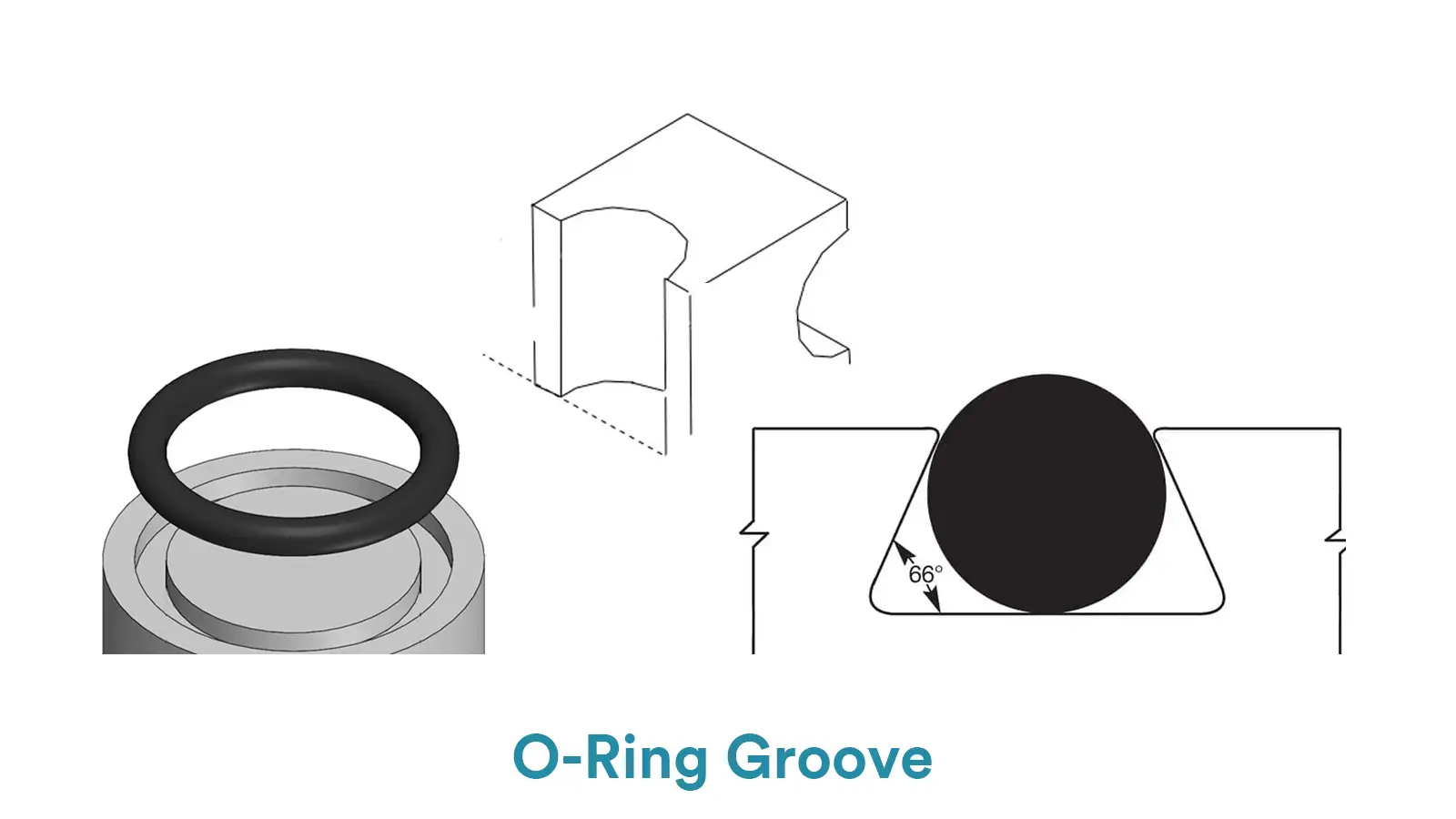
This is all about creating a seal. The groove, often cut with a grooving tool, provides a snug home for the O-ring. When two parts are assembled, the O-ring compresses within the groove, reliably preventing leaks of liquids or gases.
It is a deep, recessed area inside a part where the internal space is larger than the entrance opening.
This complex undercut requires a “lollipop” cutter (or undercut end mill) to reach under the overhangs. It’s used to create internal channels for fluids or air in manifolds and heat exchangers, or to strategically remove material for weight reduction in aerospace components without compromising the part’s outer shell.
Since a standard tool can’t access an undercut from directly above, the solutions fall into two main categories: using special tools or leveraging multi-axis machines. Here are the top 10 methods we use to bring your designs to life.
How it works: This tool has a cutting head that’s wider than its shaft. It plunges down into the workpiece and then moves sideways to undercut the overhanging material.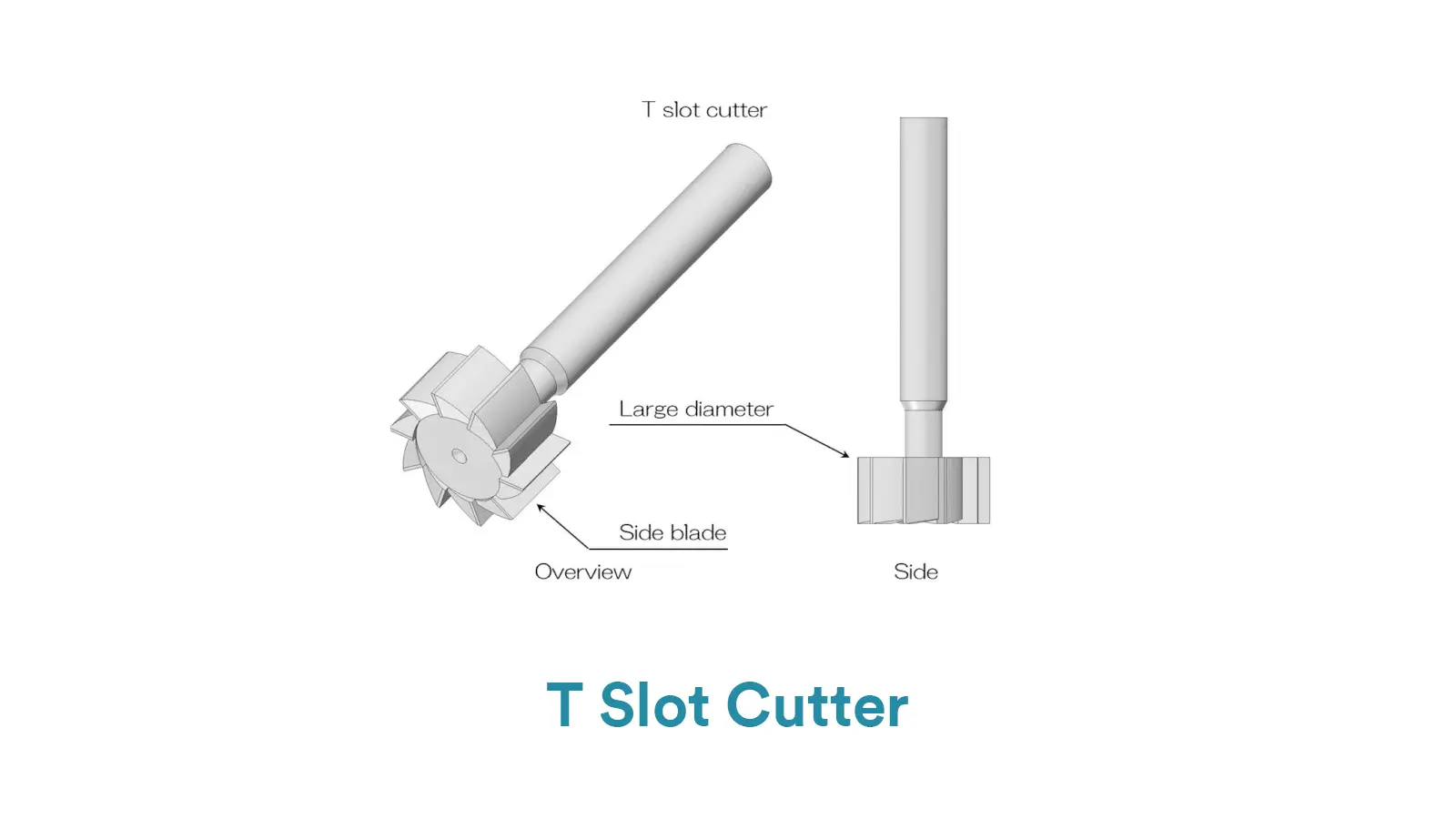
Best for: Shallow undercuts with a relatively small opening.
Pros: A cost-effective solution that works on a standard 3-axis machine.
Cons: The tool can be less rigid, leading to potential vibration. Chip removal can be tricky, and it can’t machine fully enclosed undercuts.
How it works: As the name implies, this tool is shaped to cut the angled sides of a dovetail slot in a single pass.
Best for: Creating strong, self-locking joints for machine slides and fixtures.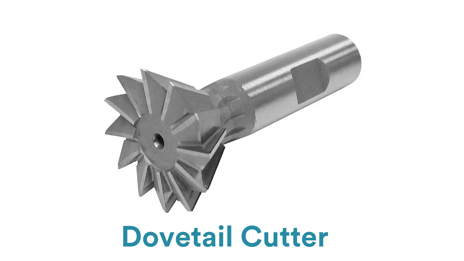
Pros: Produces a perfect, standardized dovetail profile.
Cons: Each cutter is designed for a specific angle, so flexibility is low.
How it works: This specialized tool is designed to machine a concave (inward) radius on an internal corner.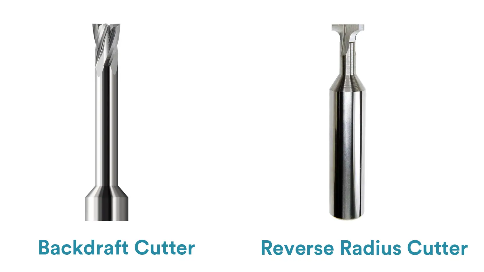
Best for: Creating smooth, stress-relieving internal radii for both aesthetics and strength.
Pros: Achieves a high-quality, clean internal fillet.
How it works: With a ball-shaped cutting head larger than its neck, it can reach underneath overhangs to machine complex contours and deep cavities.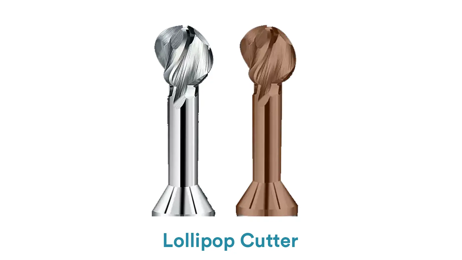
Best for: 3D undercuts, sculpted surfaces, and deburring hard-to-reach edges.
Pros: Excellent for complex, curved undercuts thanks to its large “wrap angle.”
How it works: A thin cutter with protruding cutting edges designed for cutting narrow, deep slots.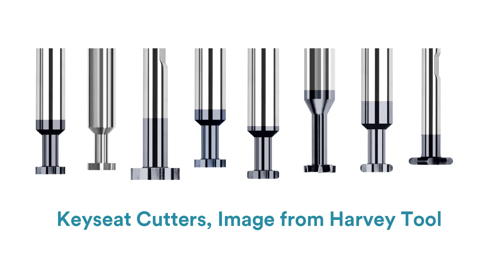
Best for: Machining keyways, thread relief grooves, and small shoulder reliefs.
Pros: Ideal for creating precise, narrow grooves.
How it works: The workpiece rotates on a 4th axis, bringing different sides into position for the tool. This turns an undercut into a feature that can be machined from a direct angle.
Best for: Undercuts that are radially spaced around a cylindrical part.
Pros: Greatly expands the capabilities of a 3-axis machine without needing a full 5-axis setup.
How it works: A 5-axis machine tilts the workpiece to a fixed, optimal angle using its two rotational axes. Then, it performs a 3-axis cutting routine with a standard, rigid tool.
Best for: Complex parts with undercuts in multiple directions, like molds or engine blocks.
Pros: Uses shorter, more robust tools for better finish and faster machining. No special tools needed.
Cons: Requires an expensive 5-axis machine and advanced programming skills.
How it works: All five axes of the machine move in a coordinated, continuous motion, allowing the tool to maintain the perfect orientation relative to the complex undercut geometry.
Best for: The most complex, free-form undercuts found in aerospace and medical implants.
Pros: The ultimate solution for geometries that are otherwise unmachinable.
Cons: The highest cost in terms of equipment, programming, and operation.
For more information about 5 axis CNC machining, visit our blog: What is 5 CNC Machining? -Everything You Want To Know
How it works: A non-contact process that uses electrical sparks to erode material. A shaped electrode slowly sinks into the workpiece, creating a perfect mirror image of itself.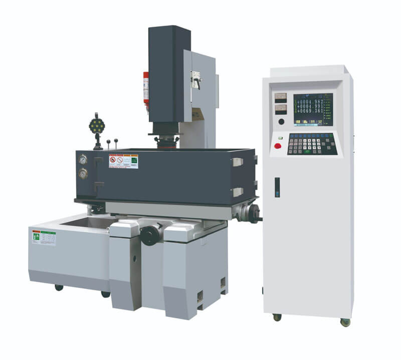
Best for: Undercuts in ultra-hard, pre-hardened materials or for creating sharp internal corners that are impossible with a rotating tool.
Pros: Can machine any conductive material regardless of hardness; no cutting forces.
Cons: Very slow and creates a characteristic textured surface finish.
How it works: The part is simply unclamped, rotated, and re-clamped in a new orientation that exposes the undercut, allowing a standard tool to machine it.
Best for: Simple parts with clear datums for accurate repositioning.
Pros: A very accessible method that uses existing 3-axis equipment.
Cons: Increases setup time and can introduce small errors from re-positioning.
With so many options available, how do you decide on the best approach for your part? There isn’t a one-size-fits-all answer, but by following a logical decision-making process, you can identify the most efficient and cost-effective method.
The choice ultimately depends on a balance of four key factors:
Start by closely examining the geometry of the undercut. Ask yourself:
Shape & Location: Is it a simple sidewall, a T-slot, or a complex 3D contour? Where is it located on the part?
Depth & Width: How deep and how wide is it? This determines the required tool length and diameter, directly impacting rigidity.
The number of parts you need dramatically influences the economics.
This is the classic trade-off in manufacturing.
Be realistic about the machinery you have access to.
In modern CNC machining, multi-axis processing is the leading trend for tackling complex undercuts because of its unparalleled flexibility and efficiency.
However, for simpler features or when working with limited equipment, T-slot cutters and strategic re-fixturing remain incredibly powerful and cost-effective choices.
By systematically evaluating your part’s geometry, production needs, budget, and tools on hand, you can confidently select the method that delivers the best results for your project.
| Undercut Type | Recommended Machining Method | Key Considerations |
|---|---|---|
| Thread/Shoulder Relief Groove | Slot Cutter or Turning Tool | Size and depth; requires high efficiency |
| T-Slot / Keyway | T-Slot Cutter or Keyseat Cutter | Slot width and depth; demands precise dimensions |
| Dovetail Slot | Dovetail Cutter | Angular accuracy and self-locking fit requirements |
| Complex Contours / Deep Cavities | 5-Axis CNC + Lollipop Cutter | Avoid tool interference; pursue surface finish |
| Hard Materials | EDM (Electrical Discharge Machining) | Material hardness; avoid stress concentration |
To properly dimension an undercut in CAD, it is recommended to follow the guidelines and best practices below to ensure the annotations are clear, readable, and meet manufacturing and inspection requirements.
Core Principle: Clear, Complete, and Unambiguous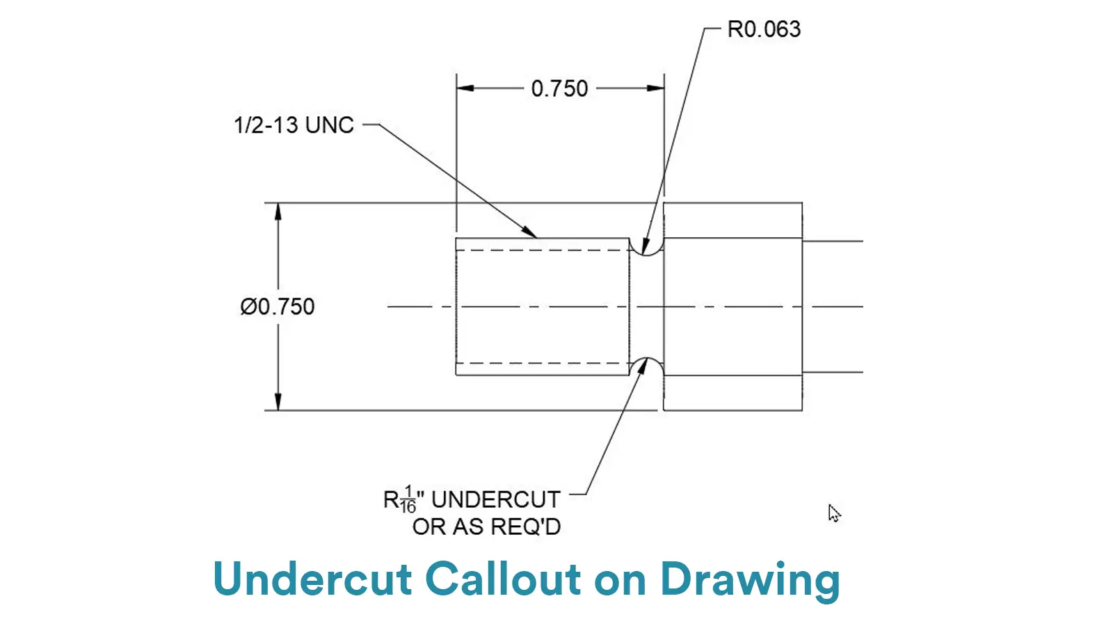
Never dimension an undercut using only hidden lines in standard orthographic views. This fails to convey its true shape and depth.
You must create a section view or a detail view to clearly display the tool path and the profile of the groove. This is the foundation for correct dimensioning.
On the section/detail view, you need to specify the following key dimensions:
Width: The opening width of the groove. For a rectangular groove, dimension the width at the bottom; for a dovetail, typically dimension the width at the opening.
Depth: The distance from a datum (like the outer diameter of a shaft) to the bottom of the groove.
Diameter: If it’s an annular groove on a revolved part, dimension the diameter at the bottom of the groove.
Angle: If the groove has an angle (e.g., a dovetail), its precise angle must be specified.
Root Radius/Fillet: It is mandatory to dimension the radius at the bottom of the groove. If a sharp corner is required, this must be clearly indicated.
Leader Notes: Use a leader pointing to the groove and add a note such as “O-RING GROOVE” or “UNDERCUT FOR SNAP RING”. This immediately informs the reader of its function.
Direct Dimensioning: Place dimension lines directly on the visible profile of the groove in the section view.
Width and Depth Tolerances: Determined by the function. For example, the width and depth of O-ring grooves typically have tight tolerances to ensure an effective seal.
Positional Tolerance: Dimension the groove’s location relative to a datum (e.g., a shaft end face) with appropriate tolerances.
The CAD dimensioning for a thread relief groove must clearly define its location, depth, and shape to guide CNC programming and quality inspection.
The axial width (L) should be specified, often defined as a multiple of the pitch (P), such as 1.5P or 2P, to ensure sufficient tool run-out space.
Crucially, the diameter at the bottom of the groove (d) must be dimensioned. For external threads, this diameter must be less than the minor diameter of the thread to ensure the mating nut can be fully tightened against the shoulder.
The root radius (R) should also be specified, as it determines the form of the grooving tool and helps reduce stress concentration.
The primary purposes of a shoulder relief are to eliminate assembly interference and disperse stress. Therefore, the focus of its dimensioning is the contour and location of the groove bottom.
The diameter at the bottom of the groove (d) and the axial width (L) should be dimensioned. The L value is typically small, serving only to provide clearance.
Most importantly, the root radius (R) must be specified. The R value is often relatively large, as a larger radius more effectively distributes stress at the shoulder, thereby improving the fatigue life of the shaft.
For high-precision assemblies, Geometric Dimensioning and Tolerancing (GD&T) might be necessary to control the perpendicularity of the shoulder face relative to the axis.
For structural undercuts like T-slots and dovetails, dimensioning must clearly define all key geometric dimensions to ensure functionality.
For a T-slot, the opening width, the bottom width, and the depth of the slot should be dimensioned. As they are often standardized features, the simplest approach is to directly reference the relevant industry standard (e.g., DIN 650).
For a dovetail slot, in addition to the top width, bottom width, and depth, the angle of the slanted side (e.g., 60°) must be clearly specified, as this is critical information for the CNC programmer to select the correct dovetail cutter.
The process for CNC machining an undercut can be summarized by a core cycle: “Analyze -> Plan -> Program -> Verify -> Execute -> Inspect.”
This is the most critical step, as it determines all subsequent processes.
Based on the feasibility analysis, develop a concrete machining plan.
Special Tool Method: For standard grooves (e.g., O-ring grooves, T-slots), prioritize T-slot cutters or grooving tools. Judge if the groove width and depth fall within the range of standard tools.
Multi-Axis Machining Method: For complex spatial undercuts, choose 3+2 axis positional machining or 5-axis simultaneous machining. Determine the required tilt angles and machining sequence.
Secondary Setup Method: If the part geometry allows, plan how to re-fixture the workpiece so the undercut area faces upwards, converting it into a standard pocket machining operation.
Combined Methods: Complex parts may require a combination of the above methods.
Special Tools: Order or grind suitable T-slot cutters, dovetail cutters, back-draft cutters, or grooving tools. Must confirm the tool’s cutting diameter, shank diameter, overhang length, and rigidity meet requirements.
Standard Tools: In multi-axis machining, use short-flute end mills with good rigidity whenever possible.
Design or select appropriate fixtures.
For the secondary setup method, precise location datums must be designed to ensure accuracy after re-fixturing.
Translate the process plan into machine-executable code.
Use CAM software (e.g., Mastercam, Fusion 360, PowerMill) to create toolpaths.
For T-slot Cutters: Typically use 2D contour milling or side milling strategies. Set correct tool parameters and cutting data (RPM, feed rate, depth of cut).
For Multi-Axis Machining: Define drive geometry and tool axis control to generate complex 5-axis simultaneous or positional toolpaths.
Undercut machining often involves less rigid tools or extended reach, necessitating relatively conservative cutting parameters.
Appropriately reduce spindle speed and feed rate, and use smaller depths of cut and stepovers to prevent tool vibration, deflection, or breakage.
This is an essential step! Simulate the entire machining process in a virtual environment.
Key Checks:
Whether the tool, holder, or collet will collide with the workpiece or fixture.
Whether the non-cutting parts of a T-slot cutter interfere with the workpiece.
Whether the machined result matches the design shape and if there is any excess material remaining.
Blank Preparation: Ensure the blank size is suitable and most of the stock has been removed.
Precise Fixturing: Securely mount the workpiece on the machine table or in the fixture according to the process plan. For secondary setup, carefully verify the location datums.
It is highly recommended to perform a test cut on scrap material or a non-critical area of the workpiece before formal machining.
Use dial indicators, pin gauges, CMMs, etc., to inspect key dimensions (e.g., groove width, depth) of the test undercut.
Only proceed with mass production after confirmation.
Pay close attention to the machine’s status during processing.
Listen for sounds: Are there abnormal vibrations or noises? This may indicate insufficient tool rigidity or improper parameters.
Observe chips: Are the chip shape and color normal?
For deep groove machining, ensure cutting fluid effectively reaches the cutting zone to aid chip removal and cooling.
After machining is complete, perform a strict inspection of the undercut feature.
Specialized Gauges for Undercut Inspection:
Pin Gauges / Plug Gauges: Check groove width.
Radius Gauges: Check root radius.
CMM (Coordinate Measuring Machine): Performs comprehensive dimensional and geometric tolerance inspection. This is the most accurate method.
Optical Comparator: Suitable for contour comparison of small parts.
Functional Verification (if applicable):
Physically install the corresponding standard part (e.g., O-ring, snap ring) into the groove to verify if the assembly is smooth and the position is correct.
When machining an undercut in CNC, the key parameters differ significantly from conventional machining due to challenging tool engagement, reduced rigidity, and difficulty in chip evacuation.
These parameters directly determine the success of the operation, the quality of the result, and tool life.
The critical parameters that must be focused on and optimized for undercut machining can be divided into three main categories: Tool Parameters, Cutting Parameters, and Path & Strategy Parameters.
Selecting the right tool is the prerequisite for success. Optimizing other parameters won’t help if the tool itself is unsuitable.
For a T-slot cutter, this is the most critical parameter: the difference between the cutting diameter (Dc) and the shank diameter (Ds).
A larger difference allows for a greater reach under the overhang but dramatically reduces tool rigidity and increases vibration risk. A smaller difference improves rigidity but limits reach.
Solution: Select a tool with the smallest possible difference that still meets the design requirement.
The length of the tool extending from the tool holder to reach the machining area.
Longer overhang increases tool deflection (bending) under load, leading to severe vibration, poor dimensional accuracy, and bad surface finish.
Solution: Use the shortest possible overhang that avoids collision with the workpiece or fixture.
Flutes: T-slot cutters typically have fewer flutes (e.g., 1-2) to provide larger chip gullets, preventing chips from clogging in the confined groove.
Helix Angle: A higher helix angle (e.g., 35°-45°) produces a smoother shearing action, reduces vibration, and aids in chip evacuation. It is preferred for difficult-to-machine materials.
Material: For materials like steel and stainless steel, prioritize solid carbide tools for optimal rigidity and wear resistance.
Coating: Coatings like TiAlN can significantly enhance tool hardness, heat resistance, and service life.
These parameters are set in the CAM software or machine control.
Axial Depth of Cut is the depth of cut in the Z-axis per pass.
Impact: A primary factor influencing cutting force and tool deflection.
Solution: A conservative, light-depth strategy is mandatory. Ap is usually much smaller than in conventional milling—often just a few percent to ten percent of the tool diameter. Achieve the total depth through multiple step-downs, not a single plunge.
Radial Depth of Cut is the width of cut in the XY plane per pass.
Impact: Directly affects lateral cutting force and surface finish.
Principle: Use a small stepover. For finishing, this might be set to 5%-15% of the tool diameter. A small stepover reduces cutting force and yields a better surface finish.
Cutting Speed is the surface speed at the tool’s cutting edge, determined by spindle speed (RPM).
Excessive speed causes rapid tool wear (especially with poor chip evacuation); insufficient speed can cause chatter.
Principle: Due to poor tool rigidity and cooling challenges, it’s often necessary to appropriately reduce the cutting speed below recommended values for conventional milling.
Feed Rate is the speed at which the tool moves through the material.
Too slow, and the tool rubs instead of cuts, generating heat and wear; too fast, and excessive cutting force causes vibration and chipping.
Principle: Find a balance. Typically, use a moderate-to-conservative feed per tooth (Fz), and ensure the machine is rigid enough to maintain a constant feed without stalling.
The machining strategy and toolpath are crucial for undercut success.
Layered Milling: Absolutely avoid a full-depth plunge. Must use layered milling, dividing the total depth into multiple small layers for step-by-step cutting.
Climb vs. Conventional Milling: Prioritize climb milling. It provides more stable cutting forces, pushes the workpiece against the fixture, and helps reduce vibration, improve surface finish, and extend tool life.
Lead-in / Lead-out is how the tool enters and exits the material.
Avoid vertical plunging. Use arc or ramp entries/exits to allow the tool to engage the material smoothly, reducing shock and tremor.
Corner Control is the tool’s behavior at path corners.
Slow down appropriately at path corners to prevent overcuts and tool deflection caused by inertia.
For easy recall and application, follow this “UNDERCUT” mnemonic:
U – Use Light Cuts: Small depth of cut and stepover.
N – No Long Overhangs: Use the shortest possible tool overhang.
D – Decrease Feed/Speed: Adopt more conservative cutting parameters than conventional machining.
E – Employ Climb Milling: Ensure stable cutting.
R – Rigorous Tool Selection: Choose the most suitable T-cutter based on the reach and material.
C – Clear Chips Frequently: Chip breaking and evacuation are critical.
U – Utilize Trochoidal Paths: For deep cavities, use trochoidal milling to distribute heat and cutting forces.
T – Test and Measure: Always perform test cuts and accurately measure the tool’s actual cutting diameter.
Final Recommendation:
Before formal machining, always perform test cuts on scrap material.
Use this to fine-tune the key parameters mentioned above and find the optimal combination for your specific machine, tool, and workpiece material.
This is the most reliable method to ensure successful undercut machining.
As a professional in the CNC machining field, the core mindset when designing an undercut must start from “Manufacturability.”
The goal is to minimize machining difficulty, cost, and risk while meeting functional requirements. Here are the key aspects to focus on:
First and foremost, tool accessibility and rigidity are the primary constraints. You must consider whether existing tooling resources can produce this feature efficiently and economically.
Prioritize designing rectangular or circular grooves that can be machined with standard T-slot cutters or grooving tools.
It is essential to check the undercut’s width and depth to ensure they match the tool’s cutting diameter, shank diameter, and acceptable overhang.
A design requiring excessively long tool overhang or large material removal will directly lead to tool chatter, deflection, or even breakage, making the part unmachinable or resulting in uncontrolled quality.
Secondly, geometry designed for the process is crucial. Always incorporate an adequate root radius (fillet) at the bottom of the groove, and avoid sharp corners. Sharp corners are stress concentrators that can initiate cracks during the part’s service life.
During machining, they are difficult to machine perfectly, often leaving behind residual material or causing rapid wear at the tool’s cutting edge.
Furthermore, carefully consider the sidewall angle. Standard vertical walls already require special tools. If you design an inward-tapered dovetail slot, it necessitates a custom dovetail cutter, which significantly increases cost and process complexity.
Moreover, the feasibility of chip evacuation and cooling must be factored into the design. Deep, narrow, and enclosed undercuts are a nightmare for chip removal.
Chips trapped inside the groove will repeatedly scratch the finished surface, prevent cutting fluid from reaching the tool tip, and cause heat buildup, leading to rapid tool wear and potential thermal deformation of the workpiece.
Therefore, without compromising function, consider the groove’s opening size or internal space to create a path for chips to escape.
Ultimately, inspectability is crucial to achieving a high-quality outcome. A well-designed undercut must also be easy to measure.
Ask yourself: Can quality inspectors effectively check the feature’s width, depth, and location using calipers, pin gauges, or plug gauges?
If the answer is no, you will have to rely on expensive and time-consuming CMM (Coordinate Measuring Machine) measurements, which can become a bottleneck in the production workflow.
In summary, when defining an undercut on a drawing, it should not be just a geometric shape.
It must be a systematic decision that integrates tooling libraries, machining strategies, cutting physics, and inspection methods.
The ultimate rule is to find the most elegant and robust balance between function and manufacturability.
The properties of the material have a decisive influence on the feasibility of undercut machining, tool selection, cutting parameters, and the final surface quality.
Because undercut machining uses special tools with long overhangs and slender shanks, which are generally more fragile than standard end mills, the effects of material properties are amplified.
Material hardness is a primary determinant of cutting forces. Higher hardness leads to greater cutting forces, increasing the load and friction on the tool.
Challenge: When machining undercuts in high-hardness materials like hardened steel or titanium alloys, fragile undercut tools (e.g., thin-shank T-slot cutters or lollipop cutters) can wear out extremely rapidly and are highly prone to chipping or breakage.
Countermeasures:
Tooling: Must use carbide tools with highly wear-resistant coatings like TiAlN.
Process: Consider non-contact methods like EDM (Electrical Discharge Machining), especially for deep, fine undercuts in very hard materials.
Thermal conductivity determines how effectively heat generated during cutting is conducted away from the cutting zone.
Challenge: Materials with low thermal conductivity (e.g., stainless steel, titanium alloys) cause significant heat to build up in the tool and cutting zone, leading to a sharp rise in temperature. This can soften the tool’s cutting edge, accelerate wear, and cause thermal deformation of the workpiece.
Countermeasures:
Coolant: Use high-flow, high-pressure coolant for sufficient cooling and chip evacuation.
Parameters: Reduce spindle RPM while potentially increasing feed rate (maintaining a suitable feed per tooth) to carry heat away quickly with the chips.
Highly ductile (plastic) materials tend to form long, continuous chips during cutting.
Challenge: In soft metals or high-ductility stainless steels, long chips can easily wrap around the tool or cause re-cutting within the narrow, confined space of an undercut. This is one of the most common problems in undercut machining and can instantly lead to tool breakage.
Countermeasures:
Tooling: Use tools with sharp positive rake angles and chip breaker designs to promote chip curling and breaking.
Programming: Employ peck milling or chip-breaking cycles to forcibly break chips, combined with high-pressure air or coolant to immediately blow or wash chips away.
Certain materials, such as aluminum alloys and low-carbon steels, tend to adhere to the tool’s cutting edge, forming a built-up edge (BUE).
Challenge: The BUE alters the tool’s geometry, reduces machining accuracy, worsens surface roughness, and, when it breaks off, can take part of the tool substrate with it, accelerating tool wear.
Countermeasures:
Coating: Select tool coatings with a low coefficient of friction (e.g., DLC – Diamond-Like Carbon) to reduce adhesion.
Speed: Adjust cutting speed, typically finding a speed range that avoids the temperature window where BUE readily forms.
In undercut machining, all material properties ultimately translate into a challenge to tool rigidity. Therefore, when selecting materials and planning, designers and engineers should strive to:
For difficult materials (e.g., titanium/high-hardness steel): Consider using 5-axis CNC to tilt the tool (reducing overhang requirements) or alternative methods like EDM.
For ductile/gummy materials: Strictly control feed rates and implement rigorous chip management to prevent chip winding.
Always prioritize high-quality carbide tools and high-performance coatings tailored to the specific material.
Due to its unique characteristics, the cost structure for CNC undercut machining differs significantly from—and is typically higher than—standard CNC milling or turning. The primary cost drivers for CNC undercut machining include the following factors:
This is the most prominent cost adder in undercut machining.
Procurement of Special Tools:
Tools like T-slot cutters, dovetail cutters, lollipop cutters, and slender grooving tools are considerably more expensive than standard end mills. They are often custom-made or produced in small batches.
Short Tool Life:
Due to the poor rigidity of undercut tools (especially those with thin necks or long overhangs), they are prone to chatter and chipping during cutting. When machining hard or gummy materials, the risk of rapid wear and breakage is very high, leading to a much faster tool consumption rate compared to standard machining.
Tool Change Time:
The need to install and remove special tools for undercut operations increases machine downtime.
Undercut machining demands higher engineering expertise and is more time-consuming.
Complex CAM Programming:
CAM programming for undercut toolpaths requires complex collision checks (between the toolholder, tool neck, and workpiece). This demands experienced engineers spending more time planning and verifying safe paths.
Simulation and Test Cuts:
Given the high risks, detailed simulation (especially in 5-axis machining) and even low-speed test cuts are often necessary to validate the program and ensure no tool interference or collisions occur, which increases setup time.
Fixture Design (Sometimes Required):
For complex undercuts that require tilting or special orientations, designing and manufacturing dedicated angled or custom fixtures may be necessary.
Although automated, the process is significantly less efficient.
Low Cutting Parameters:
To protect the fragile tools, undercut machining must use lower spindle speeds, slower feed rates, and very small depths of cut.
Extended Cycle Time:
The machining time is much longer than standard milling for a comparable feature size, directly increasing machine occupancy costs.
Multi-Axis Cost:
If 4-axis or 5-axis machines are required for the undercut, the hourly machine rate is inherently higher than that of a 3-axis machine.
Measuring and verifying undercut dimensions is more challenging.
Special Gauges:
The depth and width of an undercut often cannot be measured with standard calipers. This necessitates using special depth gauges, pin gauges, custom gauges, or expensive CMMs with special probes.
Time-Consuming Measurement:
The measurement process is complex and time-consuming, increasing the labor hours for quality inspectors.
High Scrap Risk:
If a tool breaks during the undercut operation, it can easily lead to the scrapping of the entire workpiece, resulting in the loss of material and all previous machining costs.
Design the width, depth, and corner radius of the undercut to match the specifications of commercially available standard T-slot cutters and grooving tools.
This eliminates the need for custom tools, saving on expensive custom costs and lead times, while also simplifying tool management and replacement.
Minimize the depth of the undercut as much as possible without compromising its function. A shallower depth requires a shorter tool overhang, improving rigidity.
This allows for the use of more aggressive cutting parameters and significantly reduces the risk of vibration and tool deflection.
Avoid sharp corners by designing a suitable fillet radius. This reduces stress concentration, preventing part cracking. It also allows the tool to follow a smoother path, avoiding sudden stops and turns, which helps increase feed rates and protects the tool.
Invest in high-quality carbide T-slot cutters. Opt for:
Coated Tools: Such as TiAlN, to improve wear and heat resistance.
Multi-Flute Design: Where rigidity allows, choose 2 or 3-flute tools over single-flute designs to enable higher feed rates.
Optimized Geometry: Positive rake angles and sharp cutting edges significantly reduce cutting forces.
Benefit: Longer tool life, ability to use higher cutting parameters, and better surface quality.
Do not use one T-slot cutter for the entire operation.
Roughing: First, use a standard end mill (which has better rigidity) to remove the bulk of the material in the undercut area, leaving only a small finishing allowance (e.g., 0.2-0.5mm).
Finishing: Then, use the T-slot cutter for the final one or two passes to clean up the walls and floor.
This strategy drastically reduces wear on the T-slot cutter and allows it to operate with optimized parameters during finishing, improving overall efficiency.
If a 5-axis machine is available, tilt the workpiece to an optimal angle that exposes the sidewall of the undercut directly to the spindle. This allows the use of a highly rigid standard end mill instead of a T-slot cutter.
This is a qualitative leap in efficiency and quality. It enables a significant increase in cutting parameters, yields better surface finish, and completely avoids the rigidity limitations of T-slot cutters.
Use Trochoidal Milling: For roughing the undercut, the “Trochoidal” or “Dynamic Milling” function in CAM software maintains constant tool engagement, allowing for high feed rates with low depth of cut, effectively managing heat and chip evacuation.
Climb Milling: Always use climb milling for a more stable cutting process, longer tool life, and better surface finish.
Arc Entry/Exit: Avoid straight plunges; use arc or ramp entries/exits to reduce tool shock.
Ensure high-pressure coolant is delivered accurately and abundantly directly to the cutting edge. Use coolant nozzles or “siphon tubes” to direct the flow into narrow undercut areas.
This is crucial for cooling the tool and workpiece, aiding chip breaking, and flushing chips away, preventing heat buildup and chip clogging.
Program periodic “retract” motions into the cycle. Have the tool fully exit the machining area at intervals, using a flood of coolant to thoroughly wash away accumulated chips before resuming cutting.
This prevents tool damage, surface scoring, and process interruptions caused by chip entanglement.
Do not settle for the CAM software’s default parameters. Perform test cuts and listen to the machining sounds. Start with conservative parameters and gradually, in small increments, increase the feed rate until slight vibration occurs, then dial back to a stable state.
Finding the “sweet spot” parameters for your specific machine-tool-workpiece combination maximizes material removal rate while ensuring safety.
An Undercut for Thread Relief refers to a specifically machined annular groove at the end of a threaded section on a shaft or inside a hole, where it meets a vertical shoulder or bottom.
It embodies characteristics of both an Undercut (geometric form) and a Relief (functional purpose):
It is a recessed feature that typically cannot be cut in a single pass from the side or face using a standard turning tool. It requires a narrow grooving tool to reach in and machine within the recessed area. Geometrically, it is therefore an undercut.
This is its primary engineering purpose: to provide clearance.
Tool Runout Clearance: Provides a buffer and exit area for the thread cutting tool (e.g., a single-point thread tool on a lathe), preventing the tool from crashing into the shoulder at the thread’s end, which could damage the tool or leave an incomplete thread form.
Ensures Full Assembly: Ensures that a mating nut or threaded part can be fully tightened, sitting flush against the shoulder. Without this groove, the first thread of the nut might be stopped by the residual fillet at the shoulder, preventing the nut from seating completely.
Stress Relief: A thread terminating abruptly at a sharp shoulder creates a stress concentration. A relief groove with a radiused transition helps distribute stress, improving the part’s fatigue strength.
The dimensions for a thread relief undercut are often standardized (e.g., ISO 4755 or DIN 76):
External Thread: The groove diameter must be less than the minor diameter of the thread to ensure the mating part isn’t obstructed.
Internal Thread: The groove diameter must be greater than the major diameter of the thread to ensure the threading tool can exit cleanly.
Width/Length: The groove width is typically specified to be at least 1.5 to 3 times the pitch (P) to provide sufficient runout space.
In short, a thread relief undercut is a functionally driven undercut structure and a standard practice in precision CNC turning to ensure thread quality and assembly performance.
An undercut on a shaft, often called a shoulder relief groove or clearance groove, serves several critical functions in mechanical engineering and CNC machining.
The primary purposes of a shaft undercut are to ensure the precision and reliability of component assembly while enhancing the structural integrity and service life of the shaft itself.
Here is a breakdown of its main objectives:
This is the most common reason for an undercut at a change in shaft diameter (shoulder).
Eliminates Fillet/Corner Interference: During machining, tools cannot create a perfect 90-degree internal corner and always leave a small fillet.
Mating parts like bearings, gears, or collars often have sharp internal corners. The undercut provides clearance for the sharp corner of the mating part, ensuring it seats perfectly and tightly against the shoulder face. Without it, the part might “sit on” the fillet, causing misalignment and improper load transfer.
Thread Relief: As mentioned previously, an undercut at the end of a thread ensures a nut or threaded part can be fully tightened against the shoulder.
Undercuts help manage stress concentration, which is crucial for components under cyclic loading.
Reduces Stress Concentration: A sudden change in shaft diameter (a sharp internal corner) creates a severe stress concentration point, especially under torsional or bending loads. These points are often where fatigue cracks initiate.
Design Solution: By introducing an undercut with a specific root radius, the transition in diameter becomes smoother. This distributes the stress over a larger area, effectively lowering the stress concentration factor and significantly increasing the shaft’s fatigue life.
Tool Clearance: The undercut provides necessary runout space for cutting tools to finish machining adjacent features (like a face or thread) without overcutting or dwelling at the critical intersection point.
Inspection Access: It provides space for inspection tools (like a micrometer) to safely measure an adjacent diameter without interference from the shoulder fillet.
In essence, a shaft undercut is a deliberate, functional design feature used by engineers (using the geometry of an undercut to serve the purpose of relief) to eliminate stress at critical junctions and ensure components assemble to intended tolerances and strength specifications.
Machining an annular groove on parts like pistons, valve spools, end caps, and housings that require fluid sealing, for the precise installation of an O-ring. Ensures the seal provides reliable leak-proof performance when pressurized. This is the most classic undercut application.
Machining an annular groove on a shaft or in a bore for installing a snap ring (circlip) to axially locate components like bearings and gears.
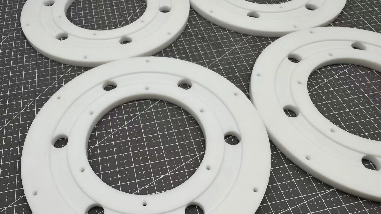
Machining a groove at the root where two vertical internal walls intersect, to provide space for cleanout tools (like T-slot cutters), achieving a sharp corner and avoiding material residue caused by the corner radius of end mills, which could affect assembly.
Used on machine tool tables in conjunction with T-bolts for flexible workpiece clamping. Primarily used for machine tables and fixtures, providing powerful fastening and clamping force via T-bolts.
Used in mechanisms like machine tool guides and slides, providing precise sliding fit and the ability to withstand unidirectional overturning moments. Used for precision guides, sliding components, or mechanical connections requiring high-strength locking, enabling self-locking and precise alignment between components.
Machining internal hook structures on plastic or metal parts to achieve sliding snap-fit connections or locking between components.
Machined on rotating components like shafts and gears that transmit torque, to accommodate a key, locking the two together and preventing independent rotation.
In summary, undercuts in CNC machining are indispensable design features that enable critical functionalities—from ensuring precise assembly and robust sealing to creating secure mechanical joints and enhancing structural integrity.
While they introduce specific manufacturing considerations, their strategic use is a hallmark of sophisticated engineering.
The key to successfully implementing undercuts lies in a proactive approach to design for manufacturability (DFM).
By optimizing features like groove geometry and depth for standard tooling, designers can mitigate complexity and control costs without compromising on performance.
Ultimately, close collaboration between design and manufacturing teams transforms the challenge of undercuts into an opportunity.
By understanding both the capabilities of modern CNC machining and the principles of efficient design, we can harness the full potential of these features to produce high-performance, reliable, and cost-effective components.
In machining and manufacturing, an undercut refers to a recessed or reduced area on a part that cannot be directly machined with standard tools.
It is commonly used in molds, thread roots, or mating surfaces to ensure proper assembly or functionality.
In contrast, relief machining involves creating intentional clearance at edges, holes, or grooves to prevent interference, stress concentration, or tool collision.
In simple terms, an undercut is a functional or structural recess, while relief machining provides auxiliary space for machining or stress relief.
A relief groove is a common functional application of an undercut structure.
For more details, check out our blog “Undercut vs. Relief.“
In CNC machining, undercut and overcut have entirely different meanings:
Undercut: An intentional design feature where engineers create recessed geometries that require special tools to machine, serving purposes like assembly, connection, or clearance.
Overcut: A machining error or defect where the tool removes more material than designed due to programming errors, tool wear, machine vibration, or incorrect compensation settings, leading to out-of-tolerance parts and scrap. It represents unnecessary and incorrect material removal.
Undercut: A complex recessed structure hidden beneath overhanging geometry, requiring special tools like T-slot cutters or lollipop cutters. Its design aims to ensure high-precision assembly, self-locking connections, or tool clearance.
Notch: An open geometric feature typically located at the edge or side of a part, easily machined with standard end mills or saw blades. Its main purpose is marking, positioning, corner clearing, or providing simple pass-through clearance.
In short, an undercut is a functionally driven, challenging recess, while a notch is a simple open cut for marking or clearance.
Undercut: A geometric concept and design feature in CNC machining and engineering, intentionally designed as an inward recess that requires special tools for machining to achieve specific assembly or functional purposes.
Underfill: A manufacturing defect commonly seen in processes like injection molding or electronic encapsulation, where insufficient pressure, temperature, or material flow prevents molten material or encapsulant from fully filling the mold cavity or intended space, leading to incomplete parts or functional failure.
Ultra-hard or brittle materials (e.g., hardened steel, ceramics) are difficult to machine for fine undercuts, as they are prone to tool chipping or part damage. It is advisable to prioritize easily machinable materials like aluminum or copper.
Undercuts enable special assembly, snap-fit connections, sliding rails, enhanced sealing, and other complex structural functions. They are commonly used in industries such as aerospace, automotive, and mold manufacturing.
Undercuts typically require specialized tools or unique manufacturing processes, significantly increasing costs and lead times, especially for non-standard dimensions.
Yes, there are strict limitations. Undercut tools (e.g., lollipop cutters) have slender shanks and long overhangs, making them very rigid.
Generally, the depth of an undercut is limited by the tool’s length-to-diameter ratio. Longer overhangs increase risks. We recommend keeping the undercut depth no more than twice its width or diameter to ensure machinability and precision.
Usually not. Due to the poor rigidity of undercut tools and their susceptibility to vibration, the precision of undercut features (especially depth and width) is generally lower than that of flat surfaces or external diameters machined with standard end mills.
We recommend using the loosest possible tolerances for non-critical dimensions to reduce scrap rates and machining costs.
Undercuts cannot be measured with standard calipers. We typically use the following methods:
Specialized Gauges/Pin Gauges: Used to inspect the diameter and width of thread relief grooves.
CMM (Coordinate Measuring Machine): Utilizes small-diameter probes to precisely reach the bottom and sidewalls of grooves, measuring the dimensions and positions of complex undercuts.
Frequently, yes. For example:
Replace Grooves with Holes: A simple pin hole can sometimes serve a similar axial positioning function as a snap ring groove.
Split Design: Divide the part with internal recesses into two halves and connect them with screws.
Change Sealing Methods: Consider using gaskets or flat seals that do not require grooves.
We are happy to explore these alternatives with you during the early design stage.
In some cases, yes—particularly when the undercut is extremely deep or has internal geometries that CNC tools cannot reach.
Yes, but they require long-reach or specialized undercut tools, and machining time will increase. We typically evaluate this based on the 3D model.
This depends on the material and tool size. For aluminum, the minimum groove width is typically around 0.5–1.0 mm, while for steel, it is slightly larger.
If a Thread Relief Groove (or Undercut) is not machined when creating a thread, the thread and nut (or mating part) cannot fully mate due to two primary issues: Manufacturing Limitations and Functional Interference.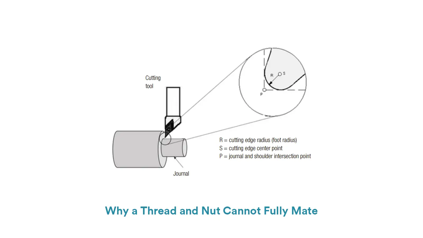
On the manufacturing side, no matter if threading is done by turning, milling, or rolling, the tool or die requires a safe exit space (Run-Out).
Without this relief groove, the cutting tool cannot instantaneously retract when reaching the vertical shoulder of the part, inevitably leaving behind incomplete, distorted thread forms and burrs at the junction.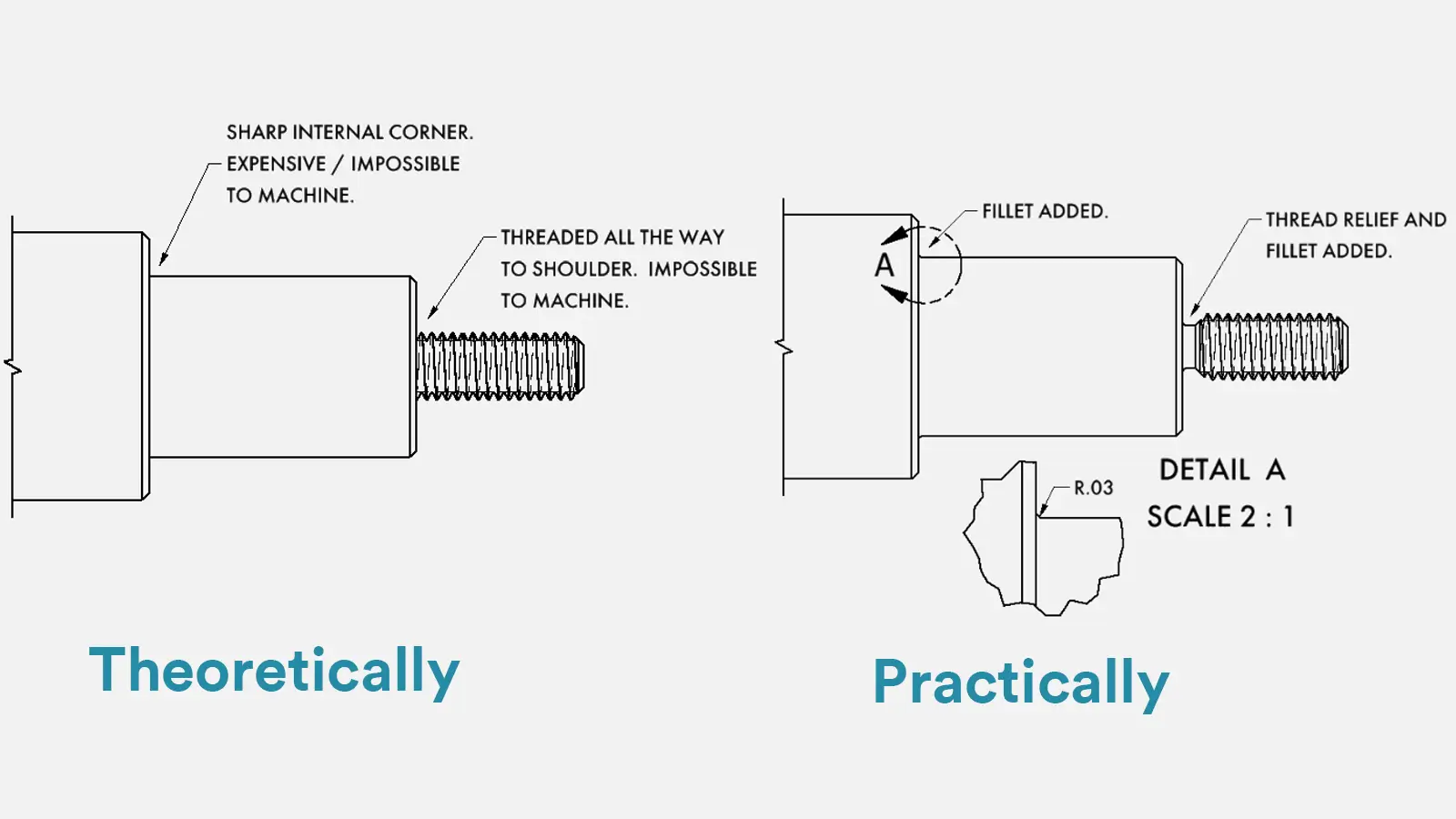
These compromised threads will block the smooth movement of the nut. On the assembly side, the internal effective threads of the nut need a clean surface to seat properly.
As the nut is screwed down, its first full thread profile will interfere with the incomplete or rounded “vanish thread” section remaining on the shaft.
This interference causes the nut to either bind up or prevent it from fully seating flush against the vertical shoulder.
The Thread Relief Groove is therefore crucial: it provides a sufficient clearance area (with a diameter smaller than the thread’s minor diameter) that allows the nut’s full threads to cleanly pass over the incomplete transition, ensuring a tight, complete fit that meets the required preload and positional accuracy.

5-Axis CNC machining is a manufacturing process that uses computer numerical control systems to operate 5-axis CNC machines capable of moving a cutting tool or a workpiece along five distinct axes simultaneously.
Both Undercut and Relief are common geometric features in CNC-machined parts. Undercut is typically driven by specific functional requirements, while Relief primarily serves manufacturing feasibility and efficiency.

Selecting the right prototype manufacturing supplier in China is a critical decision that can significantly impact the success of your product development project.

Machining tolerances stand for the precision of manufacturing processes and products. The lower the values of machining tolerances are, the higher the accuracy level would be.