 Aluminum UAV parts combine the advantages of light weight and high strength, but these benefits also make them particularly sensitive to deformation during manufacturing.
To understand how to prevent such issues, it is first necessary to examine the types of deformation that commonly occur, their impact on UAV performance, and the tolerance requirements for critical components.
This foundation establishes a clear context for analyzing the root causes and devising effective machining strategies.
Aluminum is widely used in UAV structures because of its excellent strength-to-weight ratio.
However, during machining and operation, aluminum parts often experience unexpected deformation.
These distortions are usually caused by residual stress, external forces, or thermal effects.
As a result, they can seriously affect the final quality and reliability of the drone.
Before solving deformation problems, it is necessary to understand how they appear.
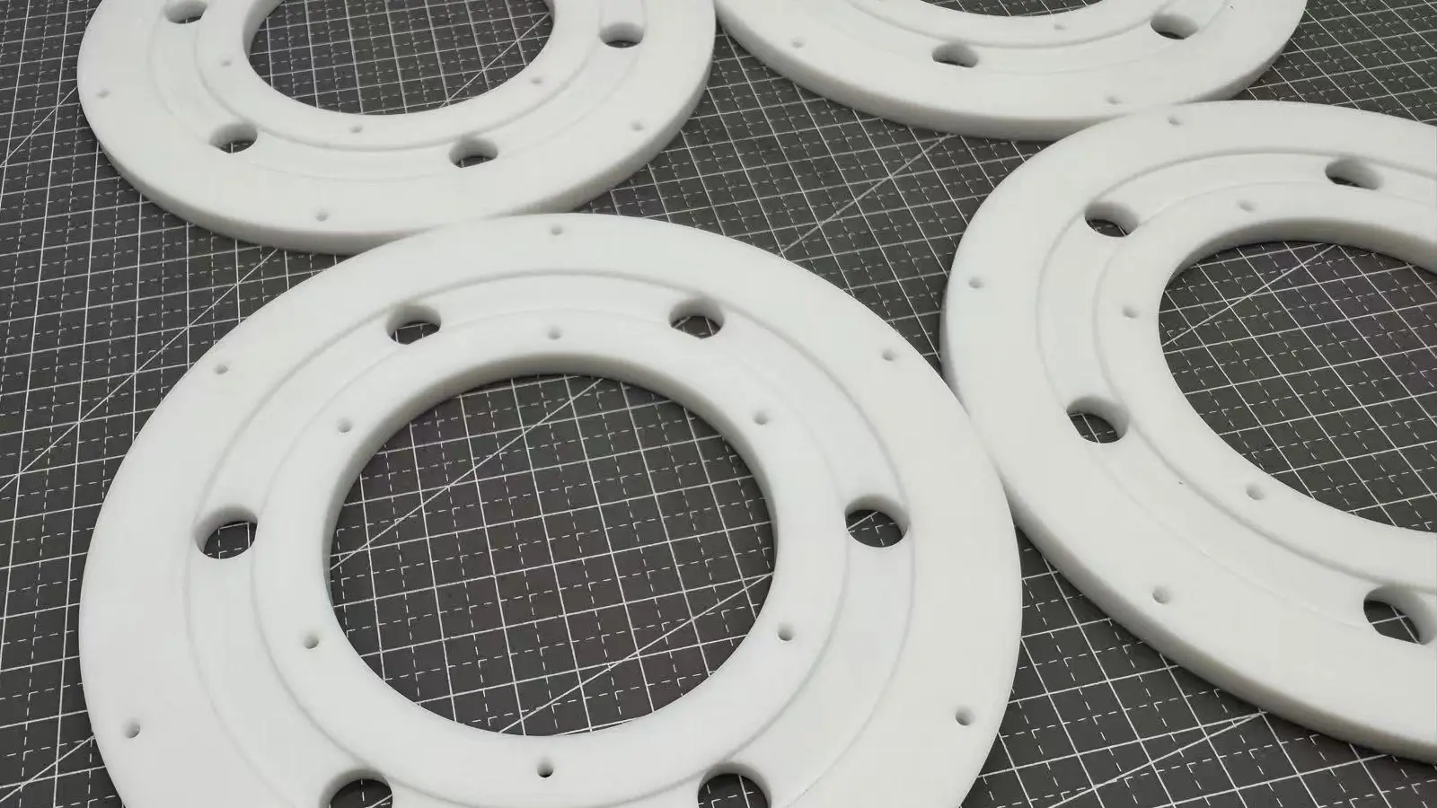
Aluminum UAV frames and housings often show several common deformation patterns during manufacturing and later use.
Slender drone arms may bend longitudinally after machining.Asymmetric processing can cause torsional deformation,and residual stress from heat treatment may lead to slow warping over time.
Thin aluminum plates tend to bulge in the center or warp at edges,reducing flatness and affecting installation accuracy.Stress release during use may further distort the plates.
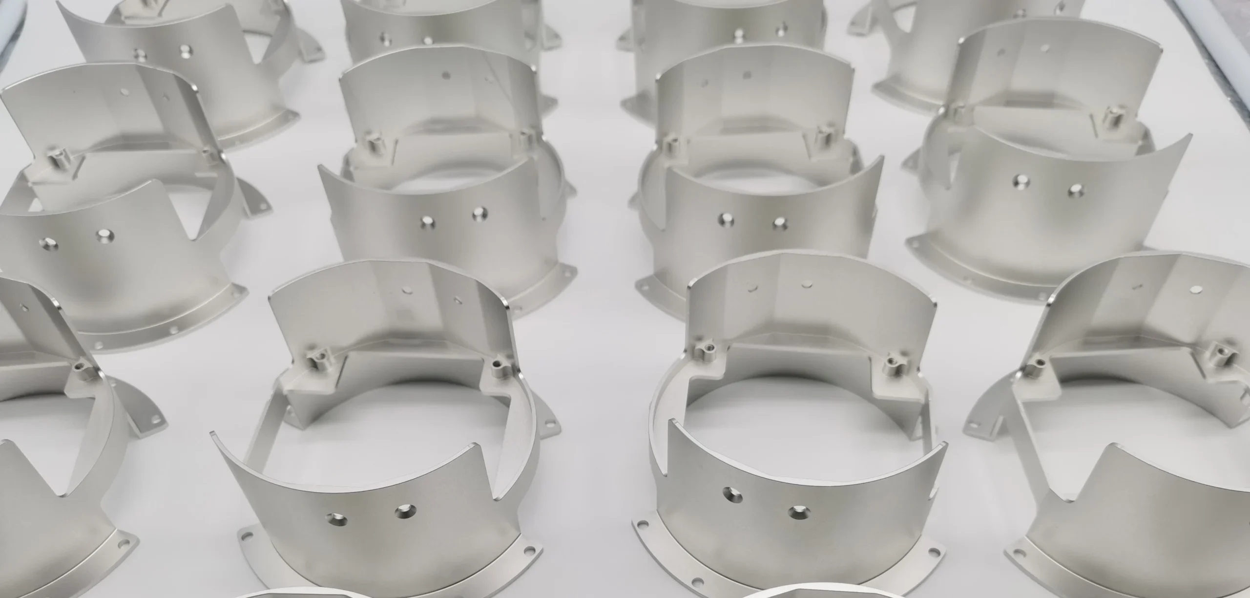
Aluminum housings are prone to local dents and bulges.
Thin-wall areas deform easily around fastening points,and curved shells may show inconsistent curvature.
Welded or connected sections are also vulnerable to irregular deformation.
Hole displacement directly affects assembly precision.
Shifted mounting holes, poor coaxiality,and tilted threaded holes are common issues.
These defects make precise assembly more challenging.
The deformation patterns above lead to geometric accuracy problems.Flatness and alignment are crucial for flight stability and assembly quality.
Flatness defects appear on surfaces used to mount motors,flight controllers, or sensors.
Multiple mounting surfaces may lose parallelism,and excessive flatness error can cause sealing failure,reducing waterproof and dustproof performance.
Alignment accuracy is critical.If the motor mounting surface is not perpendicular to the propeller axis,power efficiency decreases.
Inconsistent symmetry between arms disrupts flight balance,and misaligned module interfaces make assembly difficult.
For sliding or guiding components, poor straightness reduces motion smoothness.
Small errors can accumulate during assembly.
Multiple slightly deformed parts can amplify deviation,and forced assembly introduces internal preload stress, affecting long-term reliability.
Differences in thermal expansion between materials may also change alignment under temperature shifts.
Understanding the forms of deformation and geometric deviations helps evaluate real-world impact.
Deformation influences almost every aspect of UAV performance,from flight stability to maintenance efficiency.
Structural deformation affects aerodynamics.
Uneven surfaces increase air resistance and reduce efficiency.
Unbalanced mass distribution causes vibration.
Distorted structures may reduce control accuracy,and severe asymmetry can compromise flight stability.
Unintended deformation leads to local stress concentration.
Under cyclic loads, these areas are more prone to fatigue failure.
Bending reduces overall stiffness,and changes in natural frequency may cause resonance, posing safety risks.
Deformation creates many manufacturing challenges.
Parts may fit too tightly or misalign.
Uneven bolt preload reduces joint reliability.
Deformation can cause sealing failure.
Misalignment accelerates wear in moving parts,and deformed components are harder to replace,reducing overall maintainability.
Clear and reasonable tolerance standards are essential.
Tolerance design balances ideal performance, manufacturing capability, and cost efficiency.
Large parts may require proportionally relaxed tolerances.
Thin-wall structures need careful balance between rigidity and weight.
High-temperature environments require allowance for thermal expansion.
High-performance drones for racing or surveying usually need stricter control.
Combine first-article full inspection with batch sampling.
Critical parts should be measured using CMM equipment.
Assembly should include real-time fit checks,and dedicated fixtures improve accuracy.
Deformation of aluminum parts after machining is a common and challenging issue in precision manufacturing.
The causes are complex, often resulting from a combination of material properties, machining processes,applied forces, and structural design.
Understanding these factors is the first step toward effective prevention and correction measures.
The most fundamental internal cause of deformation is the residual stress locked inside the aluminum sheets.
This stress is not generated during machining but occurs during prior rolling and heat treatment processes.
During rolling, the surface and core of aluminum move and cool at different rates,
creating uneven stress distribution.
Typically, the surface is under compression, while the core experiences tension.
When the material is cut or milled, this delicate balance is disrupted,causing the part to warp or twist.
Especially during rough machining, rapid material removal severely disturbs the original stress balance.
To improve dimensional stability, aerospace and high-end UAV industries often use T651 aluminum,pre-treated to relieve internal stress, which significantly reduces post-machining deformation.
Beyond internal stress, machining strategy is a key external factor.
Improper material removal or tool path design can disturb the part’s stress and rigidity balance.
Milling only one side of a workpiece releases stress in that region while leaving the opposite side unchanged.
This asymmetry inevitably causes bending toward the machined side.
When one side of a cavity is milled heavily while the other remains thick,uneven stiffness can cause deformation.
Aggressive roughing strategies, such as deep cuts without layering or alternating passes,also increase thermal and mechanical stress release.
Tool paths should be designed to be uniform, symmetric, and progressive,maintaining overall rigidity during machining.
Heat generated during high-speed cutting is another major contributor.
Although aluminum conducts heat well, local hotspots can cause significant thermal expansion.
Excessive spindle speed without adequate feed prevents chips from carrying away heat,leading to localized temperature rise.
Insufficient or improperly directed coolant flow cannot control temperature effectively.
Local overheating causes expansion, and as the material cools,uneven contraction leads to deformation.
This effect is especially pronounced in thin-walled or detailed features.
The way a workpiece is fixed applies external forces.
Incorrect clamping can unintentionally induce deformation.
Excessive clamping force may cause elastic or plastic deformation.
When the fixture is removed, the part springs back, altering its shape.
Imperfect fixture surfaces can hold the workpiece in a twisted state,leading to a part that appears flat during machining but deforms upon release.
Vacuum fixtures on large thin sheets, though generally uniform,can create uneven forces if seals are misaligned or leaks exist.
UAVs prioritize extreme lightness, which requires large thin-walled structures.By nature, these structures are prone to deformation.
Reducing wall thickness decreases bending stiffness exponentially.
Even minor reductions dramatically lower rigidity,making parts highly sensitive to cutting forces, clamping, and gravity.
Large open areas without reinforcement or abrupt wall thickness changes magnify deformation risks.
Optimal designs balance weight reduction with manufacturability,using proper rib layout and smooth thickness transitions.
Machining deformation in aluminum parts is a systemic issue that spans material selection, structural design, and machining processes.
Effective control involves:
Use high-quality aluminum with low residual stress, such as T651-grade, stress-relieved alloys.
Ensure symmetric, progressive material removal and avoid aggressive cutting sequences.
Control cutting temperature via optimized spindle speed, feed, and cooling.
Use proper fixture design and clamping force to avoid induced deformation.
Consider manufacturability in the design stage, using reinforcement ribs and uniform wall thickness to reduce deformation risks.
By systematically addressing these factors,high-performance, lightweight UAV structures can maintain precision and reliability.
When aluminum parts exhibit unexpected warping or deformation after machining,
quickly and accurately identifying the root cause is critical.
A systematic diagnostic process should start with observation and measurement,progress through process and design analysis, and use logical elimination and comparative testing to pinpoint the core factors causing deformation.
Accurate measurement is the first step in diagnosis,as reliable data forms the foundation for subsequent analysis.
For flatness issues, high-precision tools are preferred.
Laser trackers or coordinate measuring machines (CMMs) with high-accuracy probes
can capture a 3D point cloud of the entire surface, generating detailed flatness maps
that precisely show bulges or depressions.
When these devices are unavailable, high-precision electronic levels on a granite surface plate or measurements using straightedges and feeler gauges along multiple diagonal directions can also provide effective quantitative data.
Measurements should simulate the part’s free state—remove it from fixtures and place it on three adjustable supports to eliminate external stress.
Only then does the measurement reflect true deformation.
It is also essential to record the deformation type:overall bending, torsion, or local indentation.
If measurements show regular or overall bending/twisting,internal residual stress is likely the main cause.
Stress-relief testing is a key method to verify this hypothesis.
Remove a small sample from a non-critical area or perform a shallow milling pass
outside the deformed region.
Observe whether the sample or part changes shape noticeably.
Significant shape changes indicate high internal residual stress,and machining disrupted the original stress balance.
Compare deformation across different batches or suppliers.
If one batch shows significantly higher deformation,it confirms poor internal stress control and highlights the importance of using stress-relieved materials like T651 aluminum.
Elastic deformation from clamping often overlaps with permanent material deformation.
Clear differentiation is crucial for accurate diagnosis.
Measure key surfaces while the part is clamped using a dial indicator or probe.
Then carefully release the part and let it rest to fully rebound,and re-measure the same surfaces.
Large differences indicate significant elastic deformation due to clamping.
Check clamp layout and force for over-constraining or local pressure issues.
If the part remains deformed after release, internal stress or thermal effects
from machining are the likely causes.
For vacuum fixtures, check gaps between the part and table at multiple points before and after machining to detect uneven suction.
Reverse-engineering deformation patterns helps quickly identify likely causes.
Specific failure modes often point to particular process or design defects.
Smooth, consistent bending often indicates residual stress release or single-sided heavy milling causing stress imbalance.
Uneven wall thickness can exacerbate this effect.
Complex distortions are usually associated with local high heat input during machining, such as high-speed milling of thin-walled areas with insufficient cooling.
Sudden local bulges or depressions suggest improper clamping,localized high pressure, or intensive machining on the backside of that region.
Unpredictable bulging or collapse in thin-walled frames or housings points to insufficient structural rigidity.
Check wall thickness, reinforcement ribs, and overall stiffness design.
If the same pattern occurs across multiple parts, the root cause is likely specific to a process, tool path, or fixture design,rather than random variation.
Diagnosing aluminum part deformation requires a logical process of elimination and verification:
Start with high-accuracy flatness measurement and detailed recording of deformation patterns.
Use stress-relief tests to distinguish residual stress-related deformation from other causes.
Compare machining-state and free-state measurements to identify elastic deformation caused by fixtures.
Match observed deformation types to known process, material, or design issues to locate root causes.
This systematic approach reduces troubleshooting time and provides a solid foundation for implementing precise corrective measures.
Preventing deformation of aluminum UAV parts is a systematic process that spans design, material selection, process planning, and execution.
Compared to correcting deformation after it occurs, proactive control measures are key to producing high-precision, lightweight parts consistently.
The core principle is to balance internal material stress, machining forces, and thermal input to eliminate or offset the root causes of deformation.
Optimizing machining processes and tool paths is the primary method for controlling forces and heat impact during machining. The goal is to maintain stability and balance throughout the process.
Divide machining into roughing, semi-finishing, and finishing stages.
Roughing quickly removes most material, allowing some cutting heat and stress while maintaining uniform allowance for subsequent operations. Semi-finishing smooths the remaining material and corrects possible roughing-induced deformation.
Final finishing uses low-stress parameters to achieve the target dimensions and surface quality.
This staged approach allows internal stresses to gradually release and rebalance between steps.
Tool paths should be symmetrical whenever possible to avoid heavy cuts on a single side. For frame parts, alternate machining opposite sides.
For cavities, use spiral or inside-outward paths to maintain rigidity symmetry.
Finishing should employ low-stress methods: sharp tools, small radial cuts, high cutting speeds, and sufficient coolant, minimizing plastic deformation and heat generation.
Cutting parameters directly affect cutting forces, heat generation, and thermal conduction. Optimizing them systematically is essential to prevent deformation.
Select a speed that balances tool life and heat generation. Excessive speed raises temperature, increasing thermal deformation risk; too low speed may cause material work hardening, increasing cutting forces.
For aluminum alloys, medium-high speeds within manufacturer recommendations are preferred, combined with effective cooling.
Ensure each tooth of the cutter engages material adequately.
Too low feed causes friction and heat accumulation; too high feed increases forces, risking vibration or tool deflection in thin walls.
Radial depth significantly impacts rigidity and forces.
For thin-walled or delicate features, use shallow radial cuts with fast feed to reduce radial force.
Axial cuts can be deeper to maintain effective tool engagement. Always ensure continuous chip formation for efficient heat removal.
Controlling internal stress at the source is one of the most effective ways to prevent deformation. Material grade, supplier, and condition are critical.
6061-T651 and 7075-T651 are common choices. 6061-T651 offers good machinability and moderate strength with stable stress, suitable for most UAV structures.
7075-T651 provides higher strength but is more sensitive to cutting parameters.
The T651 condition is essential, indicating solution heat treatment, stress-relieving stretching, and artificial aging, ensuring minimal internal residual stress and superior machining stability compared to standard T6.
For complex or high-risk parts, apply stress-relief aging after roughing.
Heat the part at a controlled temperature to relax residual stresses induced by rough machining before finishing.
Using certified, high-quality suppliers ensures batch consistency and stress stability.
Stable and well-designed fixturing and controlled environments are external guarantees for reproducible machining, directly affecting deformation control.
Follow the “N-2-1” principle (restrict N degrees of freedom) and apply clamping forces to rigid areas rather than thin walls.
Evenly distribute clamping force to avoid local elastic deformation.
Vacuum fixtures with proper seal placement provide uniform suction but must ensure surface flatness and cleanliness.
Maintain a stable ambient temperature (e.g., 20℃ ±2℃).
Avoid direct sunlight or air conditioning drafts on machines.
For precision parts, allow blanks to thermally equilibrate. Cutting fluid temperature should also be controlled, ideally using a temperature-controlled coolant circulation system.
Set up inspection stations after semi-finishing or finishing to measure critical dimensions and tolerances using dial indicators or height gauges.
This identifies deviations early and provides real-time feedback to adjust subsequent machining parameters, forming a closed-loop manufacturing control.
In summary, preventing aluminum UAV part deformation requires a holistic approach: controlling material stress, designing for manufacturability, using balanced low-stress machining strategies, and maintaining stable fixturing and environmental conditions.
Meticulous control at each stage ensures high-precision, high-performance final parts.
Preventing deformation of aluminum UAV parts is a systematic task that spans design, materials, machining, and execution.
Taking preventive measures is more effective than correcting deformations afterward.
The key is to balance internal material stress, machining forces, and heat input to eliminate or counteract deformation causes from the start.
Tool path and process optimization directly control cutting forces and thermal effects, aiming for stable and balanced machining.
Divide machining into roughing, semi-finishing, and finishing stages.
Roughing quickly removes most material, allowing limited stress release.
Semi-finishing evens out residual stress and prepares a stable condition for finishing.
Finishing uses low-stress parameters to achieve final dimensions and surface quality.
Use symmetrical tool paths to avoid removing large amounts from one side continuously.
For frame parts, alternate machining opposite sides. For cavities, use spiral or outward-expanding paths.
In finishing, apply low-stress techniques with sharp tools, small radial depth, high feed rates per tooth, and adequate cooling to minimize heat and plastic deformation.
Cutting parameters directly affect forces, heat, and stability.
Select speeds that balance tool life and heat generation.
Too high speed raises temperature and causes thermal deformation; too low speed increases cutting force and risk of chatter.
For aluminum, mid-to-high recommended speeds with effective cooling are optimal.
Proper feed ensures cutting rather than rubbing.
Too low feed increases friction and heat; too high feed increases force and vibration risk.
Maintain sufficient per-tooth feed to remove heat efficiently.
By understanding the common deformation patterns, their underlying causes, and critical tolerance requirements, manufacturers can adopt a systematic approach to control stress, optimize machining processes, and manage environmental factors.
These insights provide the basis for applying targeted preventive measures in design, material selection, and process planning, ensuring that aluminum UAV parts maintain dimensional stability, structural integrity, and reliable performance from prototype to production.

5-Axis CNC machining is a manufacturing process that uses computer numerical control systems to operate 5-axis CNC machines capable of moving a cutting tool or a workpiece along five distinct axes simultaneously.

China is the best country for CNC machining service considering cost, precision, logistic and other factors. Statistical data suggests that China emerges as the premier destination for CNC machining.

Selecting the right prototype manufacturing supplier in China is a critical decision that can significantly impact the success of your product development project.

Machining tolerances stand for the precision of manufacturing processes and products. The lower the values of machining tolerances are, the higher the accuracy level would be.