Updated: December 06, 2023
Computer Numerical Controlled (CNC) machines are highly advanced units that can machinie metal and plastic components without much labor involvement. This degree of automatization requires some programming, so the equipment units have commands to follow.
G and M code are exactly the languages that are used to program manufacturing operations. Let’s examine them in detail and compare them to each other. There also will be a review of specific instructions that you can write using G and M code and a tutorial on how to learn them.
To be precise, G and M codes are programming languages that are used to write sequences of instructions that CNC machine can read and execute.
G code is the language that has the alphanumeric format and can be used to manipulate the geometry of a CNC machine’s movable parts, like spindles. It is used to indicate what cutting tool to move, across which axis, how fast the movement should be, when to stop the tooling, etc. There are called cutting-related functions of the equipment. Or any other performance functions, like extrusion in 3D printing.
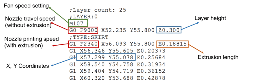
The basic structure of a G-coded command is a letter that defines a command type, a number that follows a letter and defines a command subtype, and a sequence of coordinates that regulate the movement of a movable part. You can see an example of a code for a 3D printer in the image below.
Once you have an initial insight into the general appearance of the code, let’s review what letters mean first:
It is important to mention that all CNC machines understand instructions written in this programming language. But different equipment units, especially ones that fulfill distinct manufacturing operations, do comprehend the same commands somewhat differently. That’s why there will be certain command specificities, like a number of zeros between letters, spaces between commands, etc, that depend on the unit type.
Actually, the M letter could be included in the previous section already, as it is a subtype of G code. But since it is a unique part of the programming language, it is paid particular attention. M gives ON and OFF orders, making one or another function of a CNC unit start or stop working, respectively.
Basically, any specific functions like changing tools, flooding the unit with coolant, and starting and stopping, are defined by the M code. So it is fully responsible for all the non-cutting, or rather non-direct performance operations.
In contrast to G code, M code, like any subtype, has generic values that indicate the command to be performed. The most important of them, which are usable for any CNC machine, are the following:
It is essential to know that the M code is not a distinct part of the complete program for a CNC machine. It is integrated into the list of commands within lines of G code so they both regulate each minor action for a machine to perform. So you should know them both to code the CNC programs manually.

The way G and M coding are similar or different may already be evident. But let’s summarize everything to never confuse them for sure.
| Factor | G code | M code |
|---|---|---|
| Type | Geometric/preparatory code | Machine/Miscellaneous code |
| Purpose | Regulation of all the direct performance actions, movements, and positions. | Regulation of all the non-direct performance actions. |
| Adjustment for a specific CNC machine needed | Nearly any basic command may differ depending on the equipment unit type. | Most basic commands are universal for all the unit types. But all the machines have their unique M code commands additionally. |
| Executive approach | Setting cyclic machining movements | Turning ON and OFF a specific function |
Any manufacturing process starts with a preparation of a digital 3D model – prototype. It serves the purpose of representing a future component. It is created by an engineer or a designer, or both, using computer-aided design software. In case you are already curious what are the concrete examples to download and give a try, here is the list:
While only several CAD digital tools are listed, be sure that there are many more similar options on the market. Some of them allow creating only simple designs. But others may even have a library of different materials to attribute to a part. Or have the capacity to construct an object with real dimensions, which is incredibly useful. There are software solutions that even have a CAM feature integrated.
Referring to computer-aided manufacturing (CAM) software, it is another absolutely necessary digital tool. It is completely G and M code-based and allows automation of the porting process. Or, in other words, it allows converting a CAD object to a CAM file, that a CNC unit can potentially read and execute.
CAM software scans your 3D model and ports it to a small-sized document that contains an approximate sequence of instructions that a given CNC unit should perform to cut a 3D, solid component from a workpiece. But it is a really complicated process indeed. And you almost never get the desired result that would require no manual coding and error fixing. And here are the reasons why:
The CAM software cannot produce a program intended for a particular CNC machine. So, you naturally need to revise the program. Split it, or combine distinct sets of G and M-coded instructions so your units can perform it.
This way, you will also need to adjust the program manually so it better reflects your choice of material.
In case you are not scared of the mentioned challenges of using CAM software, here are some popular tools to employ:
So, there are applications that do facilitate G and M coding. But, you still need at least basic knowledge of these programming languages to ensure the correctness of the automatically generated instructions.
In case you wonder how exactly programs written in G and M code languages control CNC machines, here is a simple explanation.
Since manufacturing units are numerically controlled, they can “read” input instructions generated with the use of symbols that such machinery is programmed to understand. So, all the basic functions for a CNC machine to perform are already inserted in it. And all you actually do is refer to these predefined commands so the machine knows which action to do in a specific moment of time.
At the same time, the software of the machine sends electronic signals to motorized, maneuverable tools of a machine – spindles. Or extruders, in the context of 3D printing. This way, separate motors make any of the movable parts perform the commanded action.
All the programs are basically sets of cyclic instructions. They define how a CNC unit must proceed with a particular workpiece, return to an initial position, wait till the next workpiece is mounted, and repeat the entire set again.
Such machinery does not have an AI-based computer vision, so it is the responsibility of the technicians to adjust each program, so it is fulfilled correctly with particular tools and over specific materials.
You need a library of the commands regardless of the software you intend to employ or the method you will be learning G and M codes with. Use the following tables of commands to construct basic programs.
| Code | Category | Function |
|---|---|---|
| G00 | Motion | Move in a straight line at rapid speed. |
| G01 | Motion | Move in a straight line at last speed commanded by a feedrate |
| G02 | Motion | Clockwise circular arc at feedrate |
| G03 | Motion | Counter-clockwise circular arc at feedrate |
| G04 | Motion | Dwell: Stop for a specified time. |
| G05 | Motion | FADAL Non-Modal Rapids |
| G09 | Motion | Exact stop check |
| G10 | Compensation | Programmable parameter input |
| G15 | Coordinate | Turn Polar Coordinates OFF, return to Cartesian Coordinates |
| G16 | Coordinate | Turn Polar Coordinates ON |
| Code | Category | Function |
|---|---|---|
| M00 | M-Code | Program Stop (non-optional) |
| M01 | M-Code | Optional Stop: Operator Selected to Enable |
| M02 | M-Code | End of Program |
| M03 | M-Code | Spindle ON (CW Rotation) |
| M04 | M-Code | Spindle ON (CCW Rotation) |
| M05 | M-Code | Spindle Stop |
| M06 | M-Code | Tool Change |
| M07 | M-Code | Mist Coolant ON |
| M08 | M-Code | Flood Coolant ON |
| M09 | M-Code | Coolant OFF |
In case you intend to fabricate components using a CNC unit, you naturally need some G coding skills.
Here is a basic program structuring overview:
And here are the useful recommendations on how to learn and implement coding successfully:
G code and M code are the basic for CNC machining. If you can understand the meaning and how to set for each command, you can apply for the CNC operator job in the market. Anybode has other questions about G and M codes in CNC machinie, you can feel free to contact us.