Understanding tolerances in CNC machining is essential because they directly affect part functionality, assembly accuracy, manufacturing cost, and overall efficiency.
Tolerances define the acceptable range of variation in part dimensions. Knowing how to set and interpret them is not just a technical detail—it’s about striking the right balance between performance, manufacturability, and cost.
If tolerances are too tight, machining becomes expensive and slow. If they are too loose, the part may not function properly or fail during assembly.
This is the core purpose of tolerances. If the tolerance is too loose, parts may not fit or may leak. If it’s too tight, parts may be difficult to assemble or even seize.
For critical components like high-speed bearing housings, leak-proof valves, or precision medical devices, tolerances directly determine the product’s reliability and lifespan. Incorrect tolerances can lead to premature wear (if too loose) or excessive friction and heat (if too tight). For instance, an optical mount with poor flatness tolerance will misalign the light path.
Tolerance callouts on engineering drawings are a “language” between designers and machinists. Understanding them helps avoid misunderstandings and machining errors.
For CAD/CAM programmers, tolerances influence toolpaths and machining strategies.
Tighter tolerances usually require more advanced machines, slower cutting speeds, and more inspections—leading to higher costs.
The tighter the tolerance, the higher the cost.
For example, tightening a tolerance from ±0.1 mm to ±0.01 mm can multiply the price.
A smart approach is to apply tight tolerances only to critical mating surfaces, while using standard tolerances on non-functional areas like covers or housings.
Understanding tolerances helps you choose the right machining process (roughing vs. finishing), select proper tooling, and write efficient G-code.
This avoids unnecessary passes, over-processing, or rework—improving consistency and productivity.
Different industries—such as aerospace, automotive, and medical—have strict tolerance requirements. Knowing and following these standards is key to producing compliant parts and passing quality certifications (ISO, ASME, etc.).
CNC machining tolerance (or simply “CNC tolerance”) is the permitted range of size variation or margin of error allowed when a part is manufactured using Computer Numerical Control (CNC) equipment.
Essentially, it’s a rule that ensures the final dimension of every feature on a part must fall within the upper and lower limits specified by the designer. As long as the finished dimension stays inside this tolerance range, the part is considered “good” or acceptable.
To break it down:
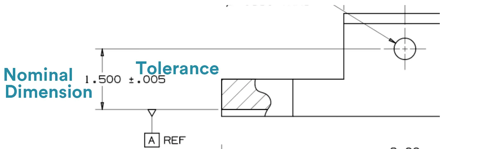
Nominal Dimension (The Ideal Number): This is the “perfect” size noted on the engineering drawing, such as 1.500 inch.
Tolerance (The Legal Range): This is the “legal range” within which the actual size is allowed to deviate from the ideal number. For example, 1.500 inch±0.005 inch.
What this means for production: Any manufactured part is considered acceptable (or “in spec”) as long as its actual size is between 1.495 and 1.505 inches.
In CNC machining, tolerances are generally categorized into four main groups: Dimensional Tolerance, Geometric Dimensioning and Tolerancing (GD&T), Fit Tolerance (ISO Fit), and Surface Roughness Tolerance.
These are the most common tolerances. They directly control the allowable variation in basic measurements like length, diameter, and angles.
Linear Tolerances
What it controls: The range for lengths, widths, and heights for almost any general part dimension.
Example:
50.00 ± 0.05 mm
25.00 +0.02 / -0.01 mm (asymmetric)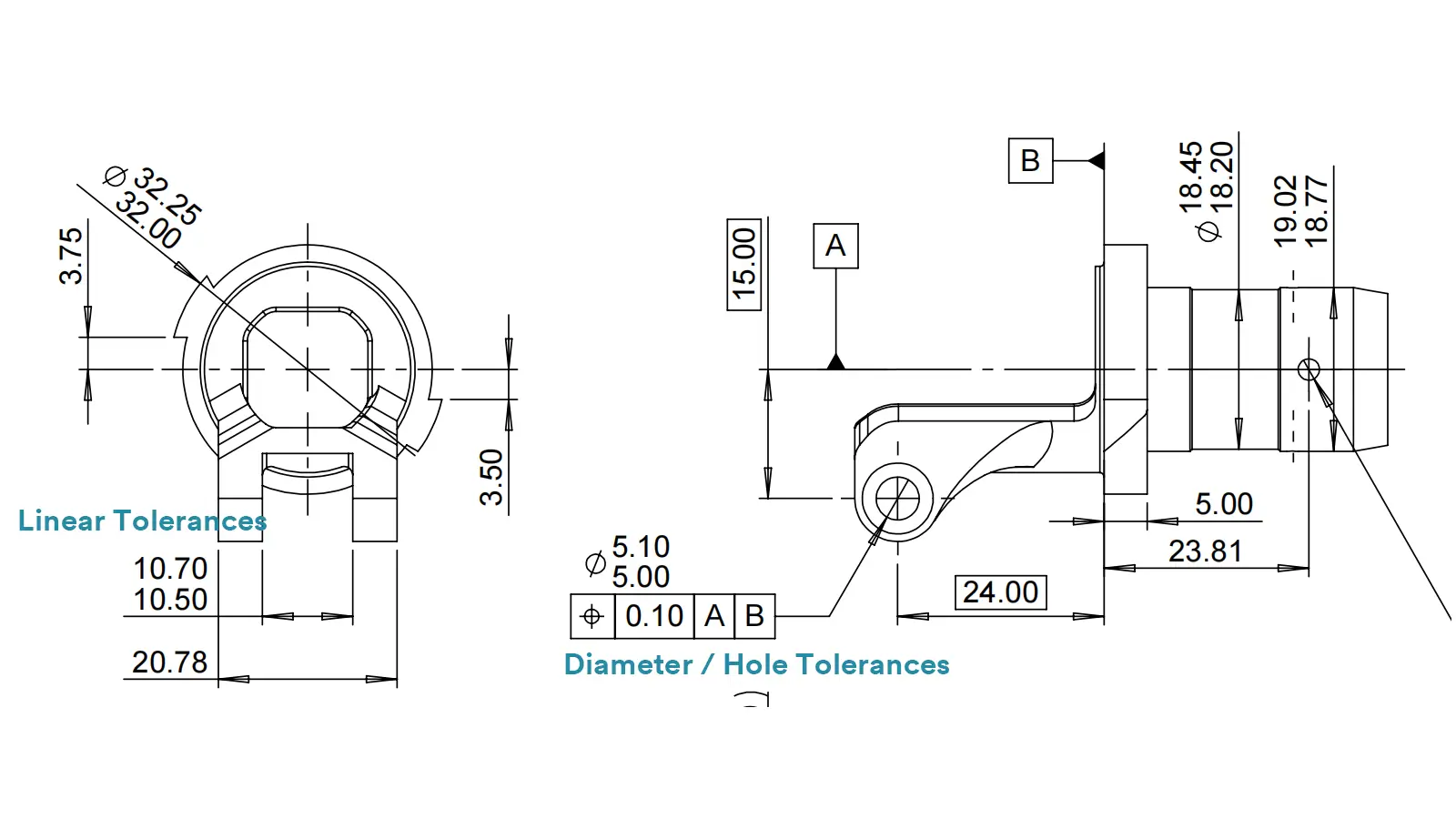
Diameter / Hole Tolerances
What it controls: The size of shafts, holes, and pins for mating parts, locating holes, and pin assemblies.
Example: Ø10.00 ± 0.01 mm or Ø8H7 (using a fit class)
Angular Tolerances
What it controls: The allowable deviation for angles on slopes, chamfers, and tapered surfaces.
Example: 90° ± 0.5° or 45° ± 0.1°
Here are the different ways you’ll see these tolerances specified on a drawing:
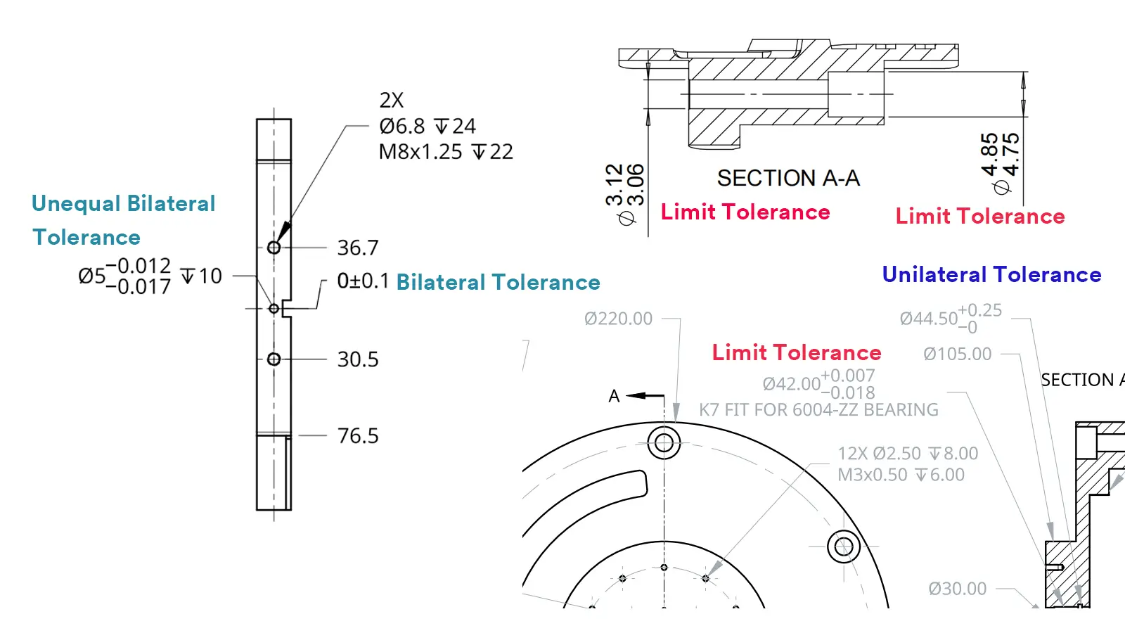
Symmetric Tolerance (or Bilateral)
The size is allowed to vary equally in both the positive and negative directions from the target. It’s the most straightforward and balanced approach. Symmetric Tolerance is for general-purpose dimensions like length, width, and standard holes.
Format: Nominal Size ± A
Example: 50.00 ± 0.05 mm means the part is acceptable between 49.95 mm and 50.05 mm.
Unequal Bilateral Tolerance
The size can vary in both directions, but one side has a looser limit than the other. This gives more flexibility where it’s needed for function or assembly. Unequal Bilateral Tolerance is used in situations where a part can better tolerate being a bit larger but not smaller (or vice versa).
Format: Nominal Size +A / -B
Example: 25.00 +0.02 / -0.01 mm means the part is acceptable between 24.99 mm and 25.02 mm.
Unilateral Tolerance
The size is only allowed to change in one direction. It can only get bigger or smaller. Unilateral Tolerance is for precision fits, sliding components, or safety-critical features where interference must be avoided.
Format: Nominal Size +A / 0 or Nominal Size 0 / -A
Example: 10.00 +0.05 / 0 means the part can be up to 10.05 mm, but cannot be smaller than 10.00 mm.
Limit Tolerance
Instead of a target size with a deviation, this method directly states the absolute minimum and maximum allowed sizes. It’s incredibly clear and leaves no room for calculation errors. Limit Tolerance is to ensure clarity and simplify inspection with go/no-go gauges.
Format: Lower Limit ~ Upper Limit or stacked vertically.
Example: 49.95 ~ 50.05 mm is the same as 50.00 ± 0.05 mm, but presented as a direct range.
Here’s a simple comparison of the most common ways to specify dimensional tolerances on a drawing.
| Feature | Symmetric Tolerance | Unequal Bilateral Tolerance | Unilateral Tolerance | Limit Tolerance |
|---|---|---|---|---|
| The Core Idea | Equal wiggle room on both sides. Balanced and simple. | Different wiggle room on each side. Flexible for function. | Wiggle room in only one direction. | Shows the absolute MIN and MAX allowed. No math needed. |
| How It’s Written | Base ± A | Base +A / -B | Base +A / 0 or Base 0 / -A | Min ~ Max or stacked |
| Example & Range | 50.00 ± 0.05 → 49.95 to 50.05 | 25.00 +0.02/-0.01 → 24.99 to 25.02 | 10.00 +0.05/0 → 10.00 to 10.05 | 49.95 ~ 50.05 24.99 ~ 25.02 |
| Need to Calculate? | Yes | Yes | Yes | No |
| Deviation Direction | Symmetrical (Up/Down) | Asymmetrical (Biased) | One-Sided Only | Implied by the limits |
| Flexibility | Medium | High | Medium (but directional) | Medium (very clear) |
| Ease of Understanding | Very Intuitive | Needs a moment to interpret | Needs attention to direction | Most Intuitive |
| Control Strictness | Standard | Can be tuned (Strict/Loose) | Quite Strict | Standard |
| Common Uses | General lengths, widths, holes. | Functional & assembly fits. | Safety features; preventing jams. | High-volume production & inspection. |
| Key Takeaway |  Simple & Balanced Easy to Read Simple & Balanced Easy to Read | Function-Driven Highly Flexible | Directional Control Prevents Interference | Crystal Clear Prevents Misunderstanding |
While dimensional tolerances control a part’s size, Geometric Dimensioning and Tolerancing (GD&T) is a system for controlling a part’s shape, orientation, and location. Think of it as the language used to define how perfectly flat, square, or concentric a feature needs to be for optimal function and assembly.
GD&T is specified using a standard “feature control frame” (a rectangular box with symbols and values) and often references one or more datums (exact points or surfaces that serve as a reference).
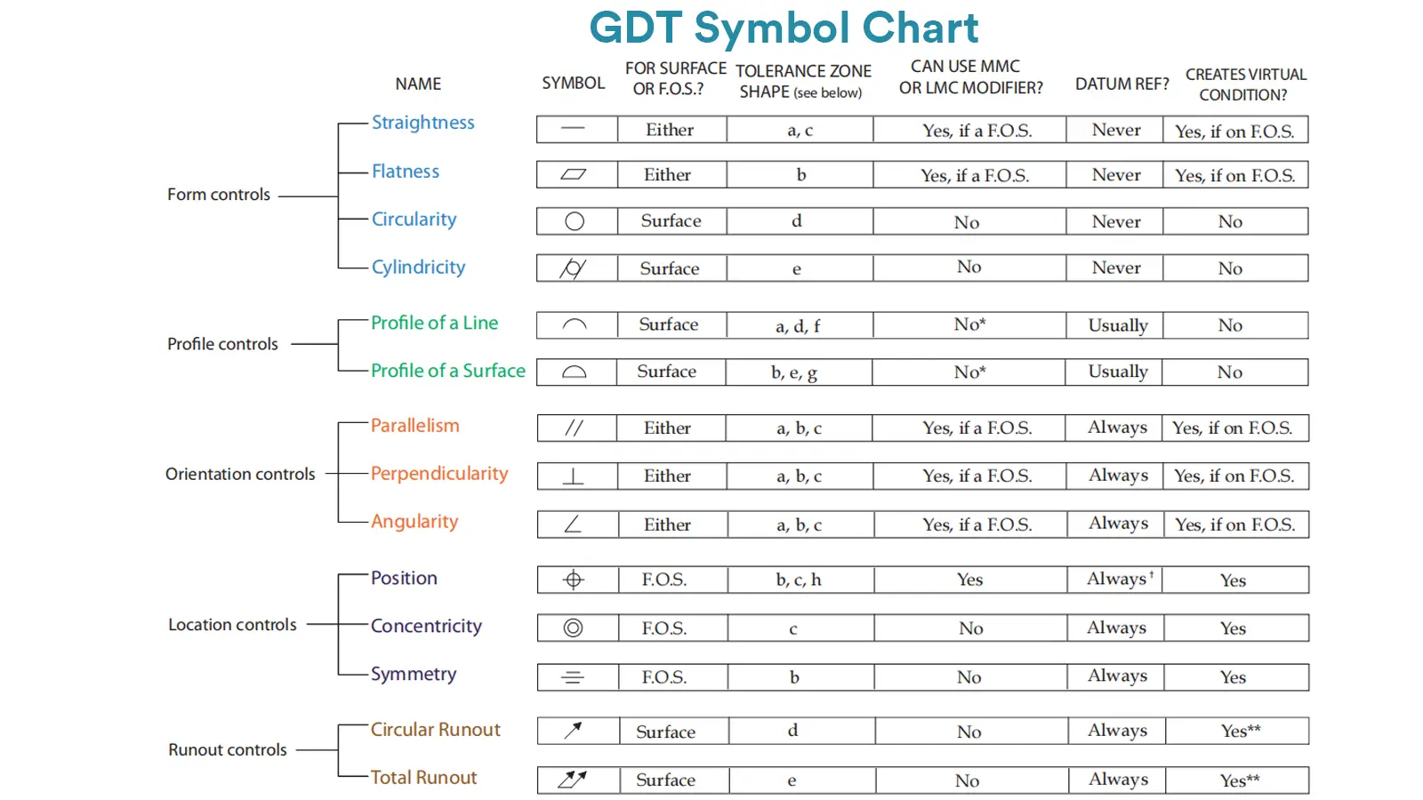
The GD&T system includes a comprehensive set of symbols. Here is a clear overview of the primary GD&T symbols and what they control, organized by category.
| Category | Control Type | Symbol | What Does It Control? | Uses a Datum? |
|---|---|---|---|---|
| Form | Straightness | — | How straight a line is along its length. | No |
| Flatness | ⏥ | How flat a surface is across its entire area. | No | |
| Circularity (Roundness) | ○ | How close a cross-section is to a perfect circle. | No | |
| Cylindricity | ⌭ | The combined roundness and straightness of a full 3D cylinder. | No | |
| Profile | Profile of a Line | ⌒ | The shape of a 2D curved line or cross-section. | Optional |
| Profile of a Surface | ⌓ | The 3D shape of a complex, curved surface. | Optional | |
| Orientation | Parallelism | // | How parallel a surface or axis is to a datum reference. | Yes |
| Perpendicularity | ⊥ | How square (90°) a surface or axis is to a datum. | Yes | |
| Angularity | ∠ | The orientation at any specified angle to a datum. | Yes | |
| Location | Position | ⌖ | The exact location of a feature (like a hole) from true position. | Yes |
| Concentricity | ◎ | How well the axis of a feature aligns with a datum axis. | Yes | |
| Symmetry | ⌯ | How balanced a feature is about a datum center plane. | Yes | |
| Runout | Circular Runout |  | The wobble or variation in a single cross-section when rotated. | Yes |
| Total Runout |  | The combined wobble and straightness across an entire surface when rotated. | Yes |
Click for more information about GDT Chart.
Fit tolerance is a crucial system (often based on the ISO standard) used to determine the exact type of assembly relationship between a shaft (or pin) and a hole (or bore). It dictates how easily one part will fit into the other.
Fits are specified using a combination of letters and numbers, such as H7/g6 or H8/f7.
The capital letter (e.g., H) refers to the hole’s tolerance zone.
The lowercase letter (e.g., g) refers to the shaft’s tolerance zone.
The number (e.g., 7) indicates the tolerance grade (the level of precision).
Example Breakdown:
Hole: Ø20 H7 → Size range: 20.000 mm to 20.021 mm
Shaft: Ø20 g6 → Size range: 19.980 mm to 19.993 mm
This guarantees a small clearance, perfect for parts that need to rotate freely, like bearings, gears, and bushings.
Click for more information about Types of Fits: How to Choose the Right Engineering Fits.
 While not a dimensional size tolerance, surface roughness is a critical tolerance that often appears alongside dimensional and geometric requirements. It specifies the acceptable “smoothness” or “texture” of the part’s surface.
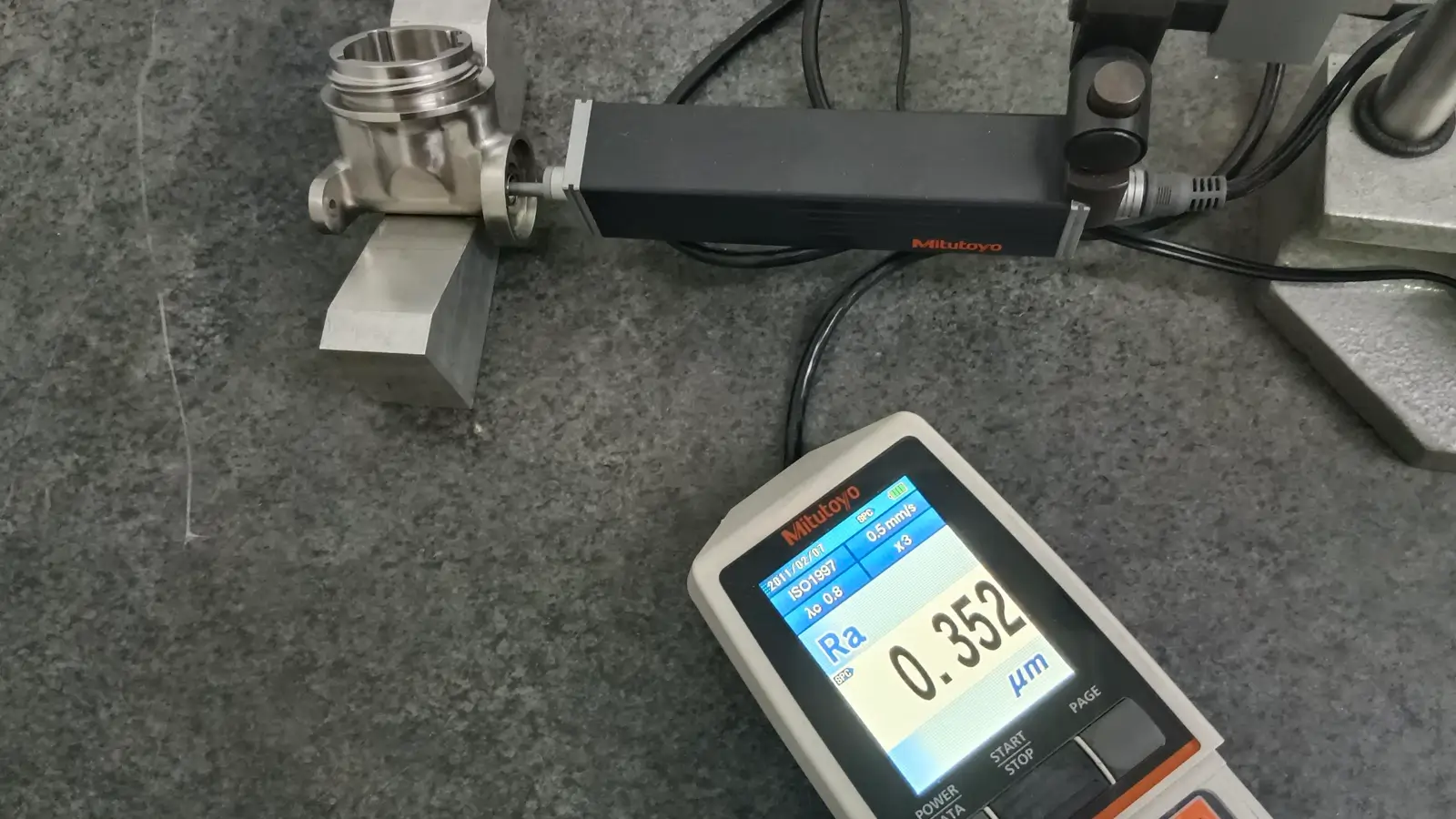
Surface roughness is most commonly expressed using the Ra value (Roughness Average), measured in micrometers (μm) or microinches.
Standard Machining: Ra 3.2 μm (Common for non-critical surfaces)
Finer Finish: Ra 0.8 μm (Often required for mating or sealing surfaces)
High Precision: Ra 0.2 μm (Needed for mirror-like finishes, medical devices, or extremely precise sliding surfaces)
Learn more information about surface roughness: The Ultimate Guide to the Surface Finish Chart
Understanding CNC machining tolerance standards from different countries is crucial for international collaboration, drawing standardization, and supply chain management.
Below are the most important and commonly used CNC tolerance standards worldwide, divided into two major categories: international general standards and national/regional standards.
These standards are designed to facilitate global trade and technical communication and are the most frequently encountered in engineering drawings.
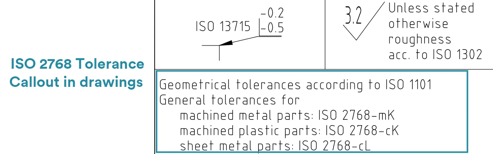
This is the most common international standard for general metal cutting (like CNC milling and turning). Its main goal is to simplify drawings by providing a set of “default” tolerances. Any dimension on a drawing that does not have an individual tolerance callout automatically follows the ISO 2768 level you specify.
ISO 2768 is divided into two parts: ISO 2768-1 and ISO 2768-2.
ISO 2768-1: For Linear and Angular Dimensions
It defines 4 grades, from most to least precise:
f (fine – high precision)
m (medium – medium precision)
c (coarse – coarse precision)
v (very coarse – very coarse precision)

ISO 2768-2: For Geometric Features (Shape and Position)
It defines 3 grades, from most to least precise:
H (high precision)
K (general precision)
L (low precision)
ISO 2768-m (Applies to size tolerances only)
ISO 2768-mK (Applies to both size and geometric tolerances)
Click for more information about ISO 2768mk tolerance: What is ISO 2768?
ISO 286-1 is a more precise and systematic standard specifically designed for cylindrical fits between shafts and holes. It uses a system of “tolerance zones” to define everything from loose, sliding fits to tight, press fits.
ISO 286-1 is called out by a tolerance code combining a letter (defining the fundamental deviation) and a number (defining the IT grade, or precision level).
Holes are designated by capital letters (e.g., H7, G6).
Shafts are designated by lowercase letters (e.g., h7, f6).
ISO 286-1 system allows designers to precisely control the clearance or interference in an assembly, ensuring consistent performance.
Here is a quick guide to the key ISO Standards for CNC Tolerancing.
| Standard | Purpose & Scope |
|---|---|
| ISO 2768-1 | General Tolerances for Linear & Angular Dimensions The default tolerances for any size that isn’t individually specified on a drawing. |
| ISO 2768-2 | General Tolerances for Geometric Features Default tolerances for form and orientation (e.g., flatness, perpendicularity) when not individually called out. |
| ISO 286-1 / 286-2 | ISO System of Limits and Fits The definitive system for specifying shaft and hole fits using codes like H7/p6 for assembly. |
| ISO 1101 | Geometrical Dimensioning and Tolerancing (GD&T) The core international standard that defines the symbols, rules, and meaning of GD&T. |
| ISO 1302 | Indication of Surface Texture Governs the symbols and notation for specifying surface roughness (e.g., Ra, Rz) on technical drawings. |
| ISO 8015 | Fundamental Tolerancing Principle Establishes the crucial rule that every tolerance is independent unless otherwise specified by a modifier like (M). |
While ISO standards are globally recognized, many countries and regions have their own established systems. Some are used alongside ISO standards, while others have been largely superseded by them.
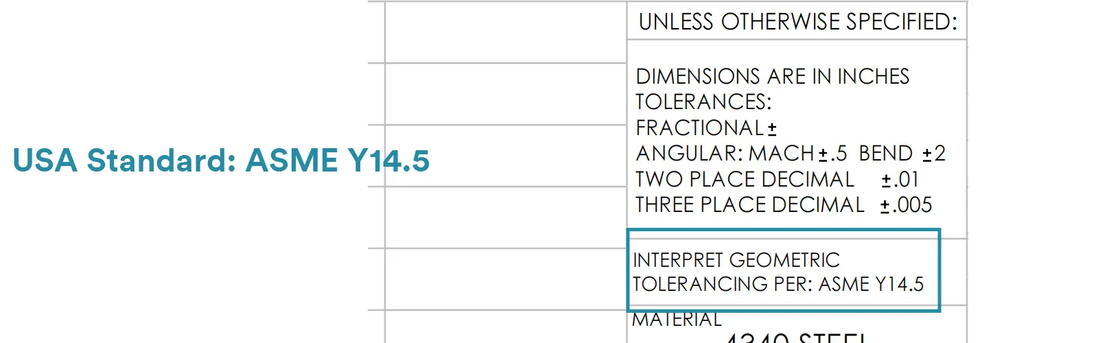
This is considered the authoritative GD&T standard in North America.
It defines:
All geometric tolerance symbols
Feature control frames
Datum systems
Material condition modifiers (e.g., MMC/LMC)
It is the primary engineering drawing standard in the U.S. and Canada. ASME Y14.5 provides in-depth rules, symbols, and methods for Geometric Dimensioning and Tolerancing (GD&T).
While largely similar in symbols and concepts to the ISO GD&T standard (ISO 1101), there are some key differences, such as the interpretation of composite tolerances and default tolerance rules.
This defines the tolerance system for shafts and holes, but may use inch-based units.
Here are the U.S. tolerance standards relevant to CNC machining.
| Standard | Purpose & Description |
|---|---|
| ASME Y14.5 | Geometric Dimensioning & Tolerancing (GD&T) Widely regarded as the most authoritative global standard for defining GD&T symbols, rules, and practices. |
| ASME Y14.5.1 | Mathematical Definition of GD&T Provides the precise mathematical foundation behind the GD&T principles in Y14.5. |
| ASME B4.1 | Preferred Limits and Fits (Imperial) Specifies standard fits for shafts and holes, similar in function to ISO 286, but for inch units. |
| ASME B4.2 | General Tolerances (Non-GD&T) Defines standard precision grades for linear and angular dimensions when no specific tolerance is stated. |
| ASME Y14.36M | Surface Texture Symbols Standardizes the symbols and callouts for specifying surface roughness. |
Germany’s well-known DIN standard system has largely adopted the international ISO standards. Drawings often show DIN ISO 2768 .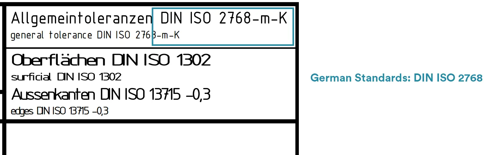
Essentially, it is the same as ISO 2768, but issued through the DIN (Deutsches Institut für Normung). It is widely used in German-speaking regions and in areas influenced by German engineering practices, such as some companies in China.
| Standard | Purpose & Description |
|---|---|
| DIN 7167 / DIN 7170 | Limits and Fits (Historical Context) These were the original German standards for defining fits between shafts and holes, largely superseded by the international ISO 286 system. |
| DIN 406 | Technical Drawing Annotation A foundational standard governing the layout, views, and text conventions used in German technical drawings. |
| DIN ISO 2768 | General Tolerances The international ISO 2768 standard for linear and geometric tolerances, adopted and published by DIN. This is the common default tolerance standard on German drawings. |
| DIN ISO 8015 | Fundamental Tolerancing Principle The international ISO 8015 standard (stating that all tolerances are independent unless otherwise specified), adopted and published by DIN. |
German manufacturing is renowned for its rigor, and DIN standards are often synonymous with high quality and precision.
Even when a standard is functionally identical to its ISO counterpart (e.g., DIN ISO 2768), its use signals adherence to the disciplined engineering culture associated with German industry.
China has a comprehensive national standard system (GB/T, Guojia Biaozhun/Tuijian), many of which are aligned with international standards to facilitate global collaboration and manufacturing.
| Standard | Purpose & Description |
|---|---|
| GB/T 1804 | General Tolerances for Linear and Angular Dimensions Without Individual Tolerance Indications This is the most commonly used general tolerance standard in China, closely corresponding to ISO 2768-1 in content and structure. It provides default precision grades for linear and angular dimensions that are not individually toleranced. |
| GB/T 1184 | Geometrical Tolerancing – Tolerances Without Individual Indications This standard corresponds to ISO 2768-2, specifying default tolerance grades for geometrical characteristics (such as straightness, flatness, parallelism, etc.) when they are not individually called out on drawings. |
Below are drawing callout examples of China CNC machining tolerance:
GB/T 1804-m (Specifies medium precision for linear dimensions)
GB/T 1184-K (Specifies medium precision for geometrical tolerances)
GB/T 1804 and GB/T 1184 together form a Chinese national standard system that is functionally equivalent to ISO 2768, ensuring compatibility with international practices.
The Japanese Industrial Standards (JIS) system is widely used in Japanese manufacturing. Similar to other national standards, many JIS standards align closely with international ISO norms to ensure global interoperability.
| Standard | Purpose & Description |
|---|---|
| JIS B 0405 | **General Tolerances** This is the primary Japanese standard for general tolerances, very similar in function and structure to ISO 2768. It defines tolerance grades such as Medium, Fine, and Coarse for dimensions without individual callouts. |
| JIS B 0401 | **Limits and Fits** This standard corresponds to ISO 286, providing a system of standard fits and tolerances for holes and shafts to ensure proper assembly and function. |
When collaborating with Japanese partners or suppliers, encountering JIS B 0405 for general tolerances is very common. Its principles and grade classifications will be familiar to anyone knowledgeable about ISO 2768, facilitating smooth technical communication.
For a better understanding of different CNC machining tolerances, we provide the two tables below.
Global CNC Tolerance Standards Comprehensive Comparison
| Region/System | Standard System | Relation to ISO | Representative Standards & Purpose |
|---|---|---|---|
| International (Universal) | ISO | Original Base Standard | • ISO 2768: General Tolerances for Linear/Angular Dimensions • ISO 2768-1/-2: General Geometrical Tolerances • ISO 286-1/-2: Shaft/Hole Fits (e.g., H7/h6) • ISO 1101: GD&T – General Specification • ISO 1302: Surface Texture Symbols • ISO 8015: Fundamental Tolerancing Principle |
| United States | ASME / ANSI | Independent System (Parallel to ISO) | • ASME Y14.5: GD&T & Authoritative Standard • ASME Y14.5.1: GD&T Mathematical Definitions • ASME B4.2: General Tolerances (Non-GD&T) • ASME Y14.36M: Surface Texture Symbols • ASME B4.2: General Tolerances • ASME B4.1: Limits and Fits (Imperial) |
| Germany | DIN | Many Formed ISO Basis | • DIN ISO 2768: General Tolerances (ISO Adoption) • DIN 7167 / 7170: Shaft/Hole Fits (Historical) • DIN 306: Technical Drawing Annotation • DIN ISO 8015: Fundamental Principle (ISO Adoption) |
| Japan | JIS | Highly Aligned with ISO | • JIS B 0401: Limits and Fits (= ISO 286) • JIS B 0405: General Tolerances (= ISO 2768) • JIS B 0021: GD&T Symbols • JIS B 0031: Surface Roughness • JIS B 0420: Geometrical Tolerancing Interpretation |
| China | GB / GB/T | Largely Equivalent to ISO | • GB/T 1804: General Tolerances (= ISO 2768-1) • GB/T 1184: Untoleranced Geometrical Tolerances (= ISO 2768-2) • GB/T 1800.2: Shaft/Hole Fits (= ISO 286) • GB/T 1958: Geometrical Tolerancing (= ISO 1101) • GB/T 1031: Surface Roughness (= ISO 1302) |
First of all, we shall note that typical CNC machining tolerance, general CNC machining tolerance, and standard CNC machining tolerances can be used interchangeably in most cases, all referring to conventional, cost-effective, and default machining tolerances.
Typical CNC machining tolerance refers to the standard level of precision that can be reliably and consistently achieved under normal production conditions, using standard equipment and processes, without significantly increasing time, cost, or complexity. Think of this as the practical, cost-effective “sweet spot” for most commercial and industrial parts.
If a drawing doesn’t specify a tolerance, a reputable manufacturer will generally machine parts to this default level of precision.
Common Typical Tolerance Ranges for Metals (e.g., Aluminum, Steel, Stainless Steel
Linear Dimensions: ±0.1 mm or ±0.005 inches
Hole Positions: ±0.05 mm to ±0.1 mm
This is a very common and practical standard, often aligning with the ISO 2768-m (medium grade).
Common Typical Tolerance Ranges for Plastics
Due to deformation and low thermal conductivity, typical tolerances are slightly wider, around ±0.1–0.2 mm. 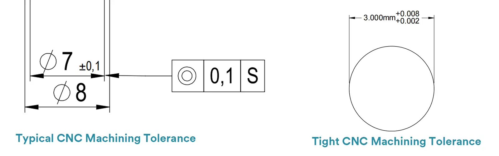
A tight tolerance (also known as a high-precision tolerance, close tolerance) is a requirement for accuracy that is significantly higher than typical tolerances, often pushing the boundaries of standard manufacturing capabilities.
Achieving these requires special effort, such as specialized equipment, controlled environments, slower machining speeds, and additional inspection.
Common Tight Tolerance Ranges for Metals
Linear Dimensions: ±0.025 mm or tighter, which is equivalent to ±0.001 inches.
In some extreme cases, even ±0.0125 mm or ±0.0005 inches can be achieved.
Common Tight Tolerance Ranges for Plastics:
Achieving ±0.05 mm is generally considered a tight tolerance for plastics, due to the material’s inherent challenges.
Note: Tolerances of ±0.01 mm and below are regarded as ultra-high precision and will result in a substantial increase in manufacturing cost. This level of accuracy is typically reserved only for the most critical mating or functional surfaces.
Here is a clear comparison between typical and tight tolerances in CNC machining, highlighting their key differences in specifications, cost, and application.
Typical CNC Tolerances vs. Tight CNC Tolerances at a Glance Table
| Feature | Typical Tolerances | Tight Tolerances |
|---|---|---|
| Typical Values | ±0.1 mm (±0.005″) | ±0.025 mm (±0.001″) or stricter |
| Cost Impact | Standard cost, best value | Significantly higher cost (often 2-5x or more) |
| Process Requirements | Standard CNC processes | Specialized equipment, strict environmental control, multi-step processes |
| Measurement Methods | Calipers, micrometers | High-precision instruments like CMMs |
| Application Scenarios | Most general-purpose parts, enclosures, brackets | Critical functional components, aerospace, medical, optics |
| Design Advice | The default choice; prioritize for cost-effectiveness | Use judiciously, only for absolutely critical features |
If you are a designer, remmember: Always start with typical tolerances for as many features as possible. Reserve tight tolerances only for those specific, critical areas where the function, fit, or safety of the part demands it. This approach optimizes functionality while minimizing manufacturing costs and lead times.
The physical and mechanical properties of materials—such as hardness, thermal conductivity, and toughness—directly affect the CNC machining tolerance that can be achieved.
Harder materials like steel resist deformation better during cutting, allowing them to hold their shape more reliably. Softer materials (like some plastics or aluminum) are more prone to elastic deformation or “tool push-off” under cutting forces, leading to dimensional inaccuracies.
Materials with high thermal conductivity, like aluminum, efficiently carry heat away from the cutting zone. This minimizes thermal expansion and results in more predictable dimensions. Materials with low conductivity, like plastics and stainless steel, tend to accumulate heat, causing the workpiece to expand locally during machining and then contract after cooling, making consistent sizing challenging.
Materials can contain internal residual stresses. When material is removed during machining, these stresses redistribute, which can cause the part to warp or distort after it’s taken out of the fixture.
Excessively tough materials (like pure copper) can form long, continuous chips that may pull at the material surface. Excessively brittle materials (like some engineered plastics) can experience chipping or micro-fractures at the edges under the cutting tool, compromising edge quality and dimensional integrity.
First, share he table below which lists typical and tight tolerance ranges achievable under standard machining conditions for different comm,on CNC materials like aluminum, steel and plastics.
Achievable CNC Machining Tolerance Ranges (Reference Values)
| Material Category | Examples | Typical Tolerance (Linear Dimensions) | Tight Tolerance (Achievable with Process Control) |
|---|---|---|---|
| Metals (Excellent) | Aluminum Alloys (e.g., 6061, 7075) | ±0.1 mm (±.004″) | ±0.025 mm (±.001″) or better |
| Metals (Good) | Steel (Mild, Alloy), Stainless Steel (e.g., 304, 316) | ±0.1 mm (±.004″) | ±0.025 mm (±.001″) |
| Metals (Challenging) | Titanium, Inconel | ±0.1 mm (±.004″) | ±0.05 mm (±.002″) |
| Plastics (Rigid) | ABS, PC (Polycarbonate), Acrylic (PMMA), Nylon | ±0.1 mm (±.004″) | ±0.05 mm (±.002″) |
| Plastics (Soft/Warp-Prone) | PP (Polypropylene), POM (Acetal/Delrin), PE | ±0.15 mm (±.006″) | ±0.1 mm (±.004″) |
Aluminum Alloys
Aluminum Alloys is often considered the ideal material for machining. It offers an excellent balance of hardness, strength, and thermal conductivity. This results in minimal thermal deformation during cutting, slower tool wear, and high-quality surface finishes.
Tolerance Guidance for Aluminum Alloys: For most applications, ±0.1 mm is a safe and cost-effective choice. For critical features, achieving ±0.05 mm is straightforward, and with optimized processes, it can even reach ±0.025 mm or tighter.
Note: Certain high-strength alloys (e.g., 7000 series) can be more abrasive on tools, but they still maintain excellent tolerance control capabilities.
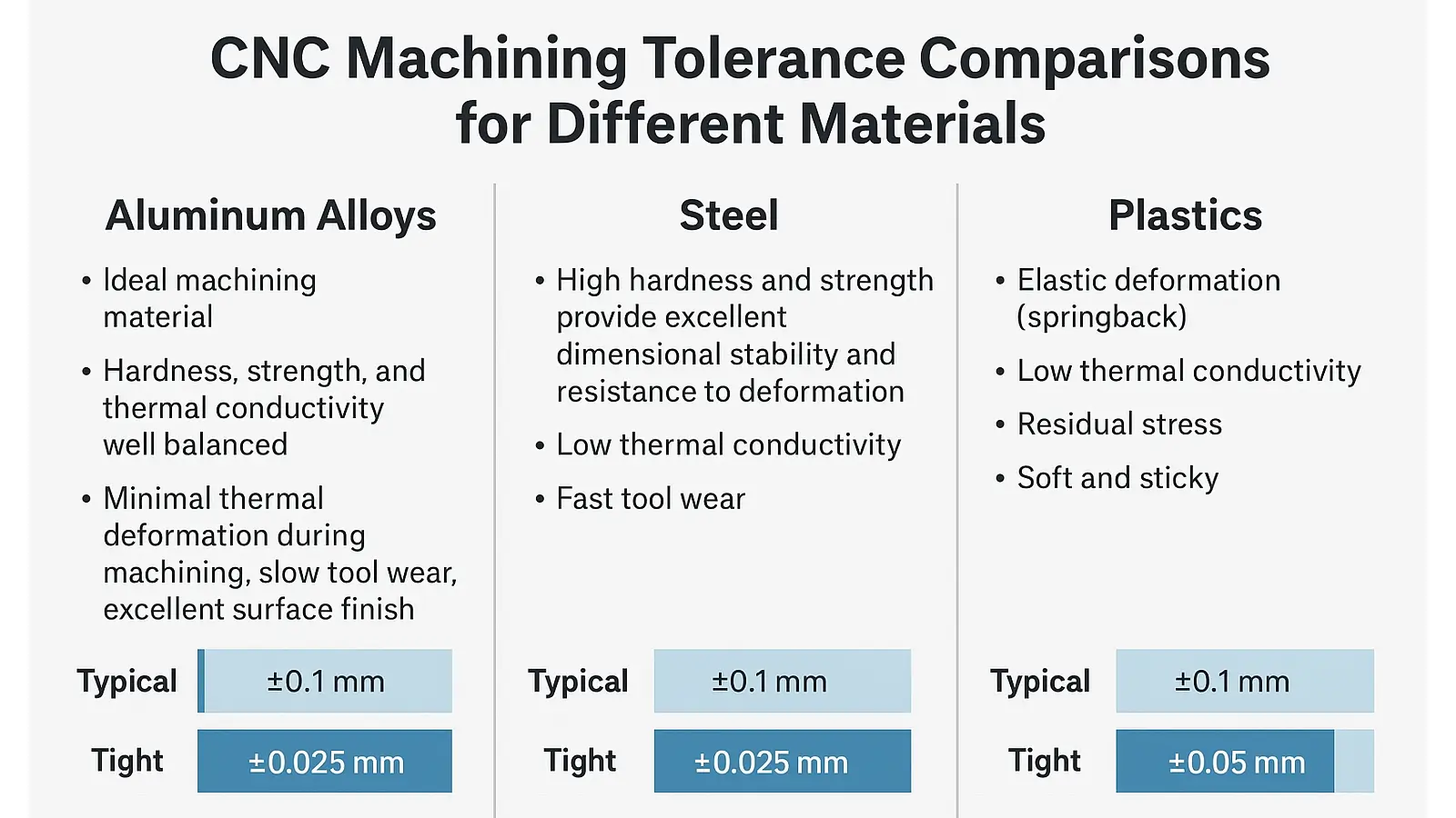
Steel (including Carbon Steel, Alloy Steel, Stainless Steel)
Steel has high hardness and strength which provide outstanding dimensional stability and resistance to deformation after machining.
Challenges of Machining Steels:
Poor Thermal Conductivity: Especially critical for stainless steels, where heat concentrates at the cutting zone, causing thermal expansion and work hardening, which can affect final dimensions.
Rapid Tool Wear: Requires more wear-resistant tools and more conservative cutting parameters compared to aluminum.
Tolerance Guidance for steel: Typical tolerances can be on par with aluminum (±0.1 mm), but achieving them often comes with higher cost and process complexity. Tight tolerances (±0.025 mm) are feasible but require significantly more effort and specialized techniques.
Plastics (including POM/Delrin, Nylon, PEEK, ABS)
Plastics presents the most difficulty for tight tolerance control.
Challenges of Machining Plastics:
Elastic Deformation (Springback): The cutting tool pressure causes temporary displacement; the material springs back after the tool passes, resulting in a cut dimension that is smaller than programmed.
Low Thermal Conductivity: Heat buildup leads to expansion during machining, followed by contraction after cooling, causing dimensional instability.
Internal Stresses: Stock materials (especially molded blanks) can contain internal stresses that are released during machining, leading to part warpage.
Softness & Gumminess: Tendency to produce burrs, affecting edge quality and dimensional accuracy.
Tolerance Guidance for plastics: It is essential to adjust expectations. Achieving ±0.1 mm is considered a good result for plastics, and ±0.2 mm is common for larger or more complex parts. Specifying tolerances like ±0.05 mm typically involves high cost and risk. Close communication with your manufacturer, including prototyping and thorough measurement, is crucial.
The type and quality of CNC equipment—along with the precision of its spindle, guides, and control systems—determine the tolerance limits it can achieve. It’s important to note that capabilities vary across CNC brands and models. The values listed below are general references.
Key Factors Influencing CNC Machine Tolerance Capability:
Machine Rigidity & Stability: High-rigidity structures reduce vibration and improve accuracy.
Spindle & Guideway Precision: Determine positioning and repeatability accuracy.
Control System Precision: Systems like FANUC and Siemens significantly impact interpolation accuracy.
Temperature Control: A constant-temperature environment greatly enhances dimensional stability.
Tooling & Fixture Quality: High-precision tools and fixtures minimize error transmission.
CNC Machine Achievable Tolerance Chart
| Equipment Type | Economical Tolerance (Recommended for Design) | Achievable Tight Tolerance (With Optimized Processes) |
|---|---|---|
| 3-Axis VMC | ±0.025 – 0.05 mm (±0.001″ – 0.002″) | ±0.0125 mm (±0.0005″) |
| 5-Axis Machining Center | ±0.05 – 0.1 mm (±0.002″ – 0.004″) | ±0.025 mm (±0.001″) |
| CNC Lathe (Turning Center) | ±0.0125 – 0.025 mm (±0.0005″ – 0.001″) | ±0.005 mm (±0.0002″) |
| CNC Mill (Entry-Level/Benchtop) | ±0.05 – 0.125 mm (±0.002″ – 0.005″) | ±0.025 mm (±0.001″) |
| CNC Grinding Machine | ±0.005 – 0.0125 mm (±0.0002″ – 0.0005″) | ±0.0025 mm or better (±0.0001″) |
| CNC Wire EDM (Slow-Speed) | ±0.003 – 0.01 mm (±0.0001″ – 0.0004″) | ±0.002 mm (±0.00008″) |
| Mill-Turn / Multi-Tasking Center | ±0.025 mm (±0.001″) | ±0.0125 mm (±0.0005″) |
Key Reminder: The values listed above are general references only.
The accuracy capabilities of CNC equipment vary significantly based on brand, model, and even maintenance condition.
A well-maintained high-end Japanese or German machine may far exceed the typical values mentioned, while an older or economy-grade machine might not consistently achieve them.
Therefore, communicating with your manufacturer about the specific capabilities of their equipment is crucial.
Selecting the appropriate tolerance is a balance between engineering requirements and manufacturing feasibility. This section explains the core elements that dictate what level of precision you can practically achieve and afford.
This is the foundational “hardware” that sets the potential accuracy limit.
As we have discussed in last section, Machine precision, rigidity, and thermal stability are key factors that determine CNC machining accuracy. The inherent precision of a machine—its positioning accuracy and repeatability—sets the hardware-based lower limit of achievable tolerance.
Rigidity also plays a critical role: insufficient stiffness in the machine, tooling, or fixtures can cause small elastic deformations under cutting forces, leading to dimensional deviations and vibration.
Thermal stability further affects accuracy, as heat generated by the spindle and guideways during prolonged operation can cause thermal expansion and alter the machine’s geometric accuracy, a phenomenon known as “thermal drift.”
Additionally, the type of machine—whether a lathe, 3-axis mill, 5-axis mill, grinder, or wire EDM—determines the specific tolerance capabilities it can achieve.
Coefficient of Thermal Expansion (CTE):
Materials sensitive to temperature changes (like certain plastics or aluminum alloys) expand under cutting heat and shrink when cooled, making stable dimensions challenging.
Hardness and Stiffness:
Hard materials (stainless steel, titanium) are difficult to cut, cause faster tool wear, and require slower speeds, increasing machining time. Soft materials can deform under clamping or cutting.
Residual Stress:
Materials may retain stress from manufacturing (casting, extrusion). Machining removes material, releasing stress and potentially causing warping or distortion, especially in thin-walled structures with large tolerances.
Thin walls: Easily vibrate or deform under cutting forces.
Deep cavities/deep holes: High length-to-diameter ratios reduce rigidity, making accuracy difficult to maintain.
Complex surfaces: Multi-axis operations introduce more sources of error.
Feature accessibility: Features difficult to reach or observe make it harder for both the operator and machine to maintain precision.
These are the software and human elements that influence the final result.
Cutting parameters: Improper speeds, feeds, or depths of cut can cause vibration, heat accumulation, and premature tool wear.
Workholding/clamping: Incorrect clamping may deform the workpiece. For example, over-clamping a thin-walled part may keep it stable during machining, but it will spring back after unclamping, altering the shape.
Cooling and lubrication: Effective cooling controls thermal deformation and extends tool life.
CAM programming strategies: Proper toolpath planning (e.g., roughing, finishing) evenly removes material, relieves stress, and ensures dimensional stability.
Measurement error: Using calipers versus a coordinate measuring machine (CMM) results in very different confidence levels in measurement.
Tools directly contact the workpiece, so their condition is critical.
Tool quality and wear: High-quality, wear-resistant coated carbide tools have longer life and stability. Worn tools directly cause undersized parts and poor surface finish.
Tool rigidity: Long, thin tools may deflect during machining, making deep holes or sidewalls less accurate.
Toolholder type: Hydraulic or shrink-fit holders provide better dynamic balance and clamping precision than standard collets, significantly improving machining stability and accuracy.
These machine, design, material, process, and tooling factors together determine the achievable CNC machining tolerance. Careful consideration of each factor is essential to select realistic and effective tolerances.
Key Factors Influencing CNC Machining Tolerances
| Category | Specific Factor | Description |
|---|---|---|
| Machine Tool Factors | Rigidity / Accuracy | Inherent geometric accuracy, axis motion precision, and backlash of ball screws. |
| Motion Control | Precision of the CNC system’s interpolation, following/servo error, and RTCP/tool compensation. | |
| Vibration | Chatter during high-speed machining or with heavy cuts adversely affecting surface finish and dimensions. | |
| Design Factors | Tolerance Selection | Balancing functional requirements with cost control. |
| Fit Requirements | Defining needs for sliding fits, press fits, and interference fits. | |
| Part Size & Geometry | Smaller features or complex free-form surfaces are more challenging for tight tolerances. | |
| Material Factors | Material Type | Aluminum and copper are easier; high-hardness steels and titanium alloys are more difficult. |
| Thermal Expansion | Heat generated during machining affects dimensions, especially in plastics and large parts. | |
| Internal Stress | Residual stresses in the material can cause distortion after machining. | |
| Tool Wear | Gradual tool wear leads to dimensional drift over time. | |
| Tooling Factors | Tool Rigidity | Long reach or small diameter tools are prone to deflection/vibration, reducing accuracy. |
| Tool Selection | Micro-tools, solid carbide tools, or specialized tooling are better suited for tight tolerances. | |
| Process Factors | Machining Method | Different capabilities of milling, turning, grinding, EDM, and laser processes. |
| Cutting Parameters | Settings for feed, rate, depth of cut, and use of coolant/lubricant. | |
| Fixturing & Location | Unstable fixtures or poor repeatability cause positional errors and dimensional deviation. | |
| Inspection & Measurement Factors | Metrology Tool Accuracy | Capabilities of tools like micrometers/calipers vs. CMMs. |
| Operator Skill | Measurement technique and environmental affects result reliability. | |
| Environmental Factors | Temperature / Humidity | Precision CNC machining often requires a controlled environment. |
| Vibration / External Forces | External vibrations from the factory floor or nearby heavy equipment. |
Selecting tolerances is a balancing act between function, cost, and manufacturability. Follow these steps to make informed decisions.
Step 1: Define Functional Requirements (The Most Important Step)
For every feature requiring a tolerance, ask yourself: What is the function of this dimension?
Non-Critical Features (appearance parts, non-mating surfaces): e.g., enclosures, heat sinks, handwheels. Select the loosest practical tolerance (e.g., ISO 2768-m or c grade).
Sliding/Running Fits: Require a specific clearance, e.g., shafts in bearings, pistons in cylinders. Refer to ISO 286-1 fit classes like H7/f7 or H7/g6.
Press Fits/Interference Fits: Require an interference, e.g., bearings pressed into housings. Refer to ISO fits like H7/p6 or H7/s6.
Precision Location Features: e.g., bolt hole patterns, dowel pin holes. Use Geometric Tolerancing (like Position) to precisely control their location.
Golden Rule: Design for function, not for precision.
Step 2: Apply the “Tolerance Selection Checklist”
Quickly identify a suitable tolerance range based on function:
| Feature Type | Recommended Starting Point | Notes |
| Non-Critical (Cosmetic) | ISO 2768-c /±0.2 mm | Lowest cost option. |
| General Machining | ISO 2768-m / ±0.1 mm | The standard, cost-effective default. |
| Sliding Fits | ISO H7/g6 or f7 | Provides controlled clearance. |
| Press Fits | ISO H7/p6 or s6 | Provides controlled interference. |
| Critical Locations | GD&T Position Tolerance | Defines a tolerance zone, often more forgiving than tolerances. |
Step 3: Prioritize GD&T for Complex Fits
For critical mating features, try to use Geometric Dimensioning and Tolerancing (GD&T) instead of traditional plus/minus tolerances.
GD&T clearly defines the part’s functional datums and can allow for a larger tolerance zone without compromising function (e.g., a position tolerance is often more flexible and functional than a bilateral tolerance). This ensures functionality while potentially reducing scrap rates.
Step 4: Consider Tolerance Stack-Up
Analyze the chain of dimensions. When one feature’s location depends on multiple other dimensions, their tolerances accumulate (stack up).
Identify the final, most critical dimension that needs to be controlled.
If the stacked tolerance exceeds the functional limit, dimension directly from a key datum to avoid relying on the sum of intermediate tolerances.
Step 5: Consider Cost and Manufacturing Feasibility
Remember the “precision premium”. Tightening a tolerance from ±0.1 mm to ±0.05 mm may increase cost by 30-50%. Tightening further to ±0.025 mm can double the cost or more.
Discuss your drawings and functional needs with your machining partner early. They can provide feedback from a manufacturing perspective, e.g., “This wall is too thin to hold ±0.05mm reliably; we suggest relaxing the tolerance or modifying the design.”
Establish clear datums (A, B, C) on your drawing and dimension geometric tolerances from them. This tells the manufacturer the priority and reference frame for achieving accuracy, reducing ambiguity.
Summary: The Four Principles of Effective Tolerance Selection
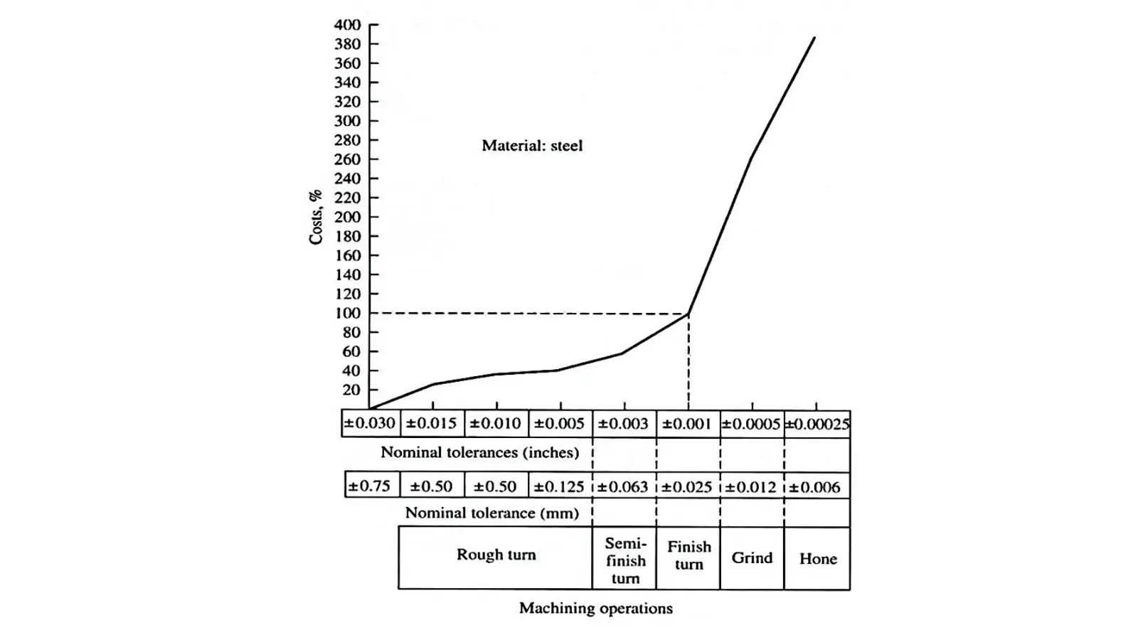
The relationship between tolerance and cost is monumental, so we dedicate more information to this critical topic.
As a customer, you frequently hear the advice: “Loosening your tolerances saves money.” But do you truly grasp the vast difference in the cost curve? The reality is that a minor tightening of tolerance results not in a linear cost increase, but in a surprising exponential growth curve.
Many clients assume that increasing precision from ±0.1 mm to ±0.05 mm should result in a reasonable 20−30% cost increase. The reality is much harsher.
| Tolerance Level | Cost Multiplier (Relative to ±0.1 mm) |
|---|---|
| Typical ±0.1 mm (±0.004 inches) | Base Cost (1x) |
| Tight ±0.025 mm (±0.001 inches) | 1.5 to 3x Base Cost |
| Ultra-Precision ±0.01 mm (±0.0004 inches) | 3 to 5x Base Cost |
Note: Moving from ±0.1 mm to ±0.01 mm can easily increase costs by 3 to 5 times, yet the performance benefit to your product may be negligible. This decision requires extreme caution.
The reason costs skyrocket lies in the implicit investment required for tooling and quality inspection:
Typical Tolerance: Uses standard carbide tools which are low-cost and have predictable lifespans.
Tight Tolerance: Requires specialized, high-precision tools, mirror-finish endmills, diamond abrasives, etc. These tools can be multiples or even tens of times more expensive, wear out faster, and require frequent, costly replacement.
Typical Tolerance: Uses calipers and micrometers for simple spot checks. This is highly efficient, and the cost is nearly negligible.
Tight Tolerance: Mandates high-precision equipment like Coordinate Measuring Machines (CMM), laser scanners, or optical systems for full inspection or high-frequency sampling.The equipment itself is expensive (hundreds of thousands to millions of dollars).
Inspection time increases dramatically (a single part can take minutes or even hours to measure).
Requires higher-paid, specialized QC technicians.
Requires rigorous environmental conditions (temperature/humidity control).
At ECOREPRAP, our team of expert engineers uses in-depth Design for Manufacturability (DFM) analysis to help clients:
Identify and eliminate unnecessary “cost trap” tolerances on your blueprints.
Provide you with the most competitive quotation while guaranteeing 100% functional reliability for your product.
Use our expertise and machine capabilities to ensure every dollar you spend delivers maximum functional value.
Tolerance vs. Cost: A Practical Breakdown
| Tolerance Requirement | Key Processes | Measurement Method | Yield Rate | Relative Cost (Est.) | Customer Value Analysis |
|---|---|---|---|---|---|
| ±0.1 mm | Standard 3-axis CNC, single setup | Caliper spot-check | >99% | Benchmark (1x) | Best value. Ideal for most assemblies; fully meets functional requirements. |
| ±0.01 mm | High-precision CNC, roughing & finishing | 100% CMM inspection | ~90% | 3x – 5x | Significant cost increase. Justified only for critical mating features. Assess if truly necessary. |
| ±0.005 mm | Precision CNC + Grinding process | 100% inspection with ultra-precision CMM in climate-controlled room | ~70% | 8x – 15x or higher | Exponential cost. Reserved for extreme fields like aerospace/medical implants. Over-engineering for most applications. |
The aerospace industry demands extreme precision, with typical aerospace CNC tolerance standards ranging from ±0.005 mm to ±0.01 mm.
This level of high precision CNC machining is critical for components like turbine blades and structural elements where minimal deviation could compromise safety.
Materials like titanium and high-temperature alloys require advanced 5-axis systems and rigorous inspection protocols to maintain these strict standards.
Medical device manufacturing maintains exceptionally tight medical CNC tolerance requirements, typically ±0.005 mm for implants and instruments.
This surgical instrument precision ensures perfect functionality and sterility, while implant manufacturing tolerance standards guarantee proper fit and biocompatibility.
The industry relies on specialized machining centers and comprehensive CMM verification to achieve these rigorous specifications.
The automotive sector balances precision with volume production, implementing automotive CNC tolerance standards of ±0.01-0.02 mm for critical components.
This gear housing tolerance precision ensures reliable power transmission, while engine component precision maintains optimal performance and emissions control.
Modern automotive manufacturing combines high-volume machining capabilities with strict quality control measures.
Electronics enclosures require specific electronics CNC tolerance parameters, generally ±0.1-0.2 mm, to ensure perfect assembly and aesthetic consistency.
This connector housing tolerance guarantees proper electrical connectivity, while maintaining consumer device precision for seamless user experience.
The industry utilizes high-volume CNC machining and precision molding to achieve these standards cost-effectively.
Robotics and automation systems demand rigorous industrial automation CNC tolerance standards, typically ±0.01-0.02 mm for moving components.
This precision automation components requirement ensures reliable operation and repeatability, while mechanical automation tolerance standards maintain system integrity under continuous operation. Specialized machining processes and regular calibration maintain these precision levels.
Other industries maintain their own specific standards – mold and die making requires ±0.005-0.01 mm for precision tooling, while energy sector components need ±0.01-0.02 mm for reliable operation in demanding environments.
Each sector’s tolerance requirements reflect its unique operational demands and quality standards.
Comparison of CNC Machining Tolerance Requirements Across Industries
| Industry Sector | Typical Tolerance Range (mm) | Primary Drivers | Key Application Examples | Common Materials |
| Aerospace & Defense | ±0.005 – 0.01 | Safety, Reliability, Extreme Environment Performance | Engine blades, Landing gear, Missile components | Titanium alloys, Superalloys, High-strength aluminum |
| Medical Devices | ±0.005 (esp. implants) | Biocompatibility, Patient Safety, Functionality | Artificial joints, Bone screws, Surgical robot parts | Medical-grade Stainless Steel, Titanium, PEEK |
| Automotive Industry | Critical: ±0.01 – 0.02 | Reliability, Durability, Mass-Production Cost | Engine blocks, Transmission gears, Drive shafts | Aluminum alloys, Cast iron, Alloy steel |
| Non-Critical: ±0.05 – 0.1 | ||||
| Industrial Automation | Moving Parts: ±0.01 – 0.02 | Repeatability, Equipment Lifespan, Operational Efficiency | Robot arms, Linear guides, Ball screws | High-strength Aluminum, Steel |
| Structural: ±0.05 | ||||
| Consumer Electronics | ±0.1 – 0.2 | Assembly Fit, Aesthetic Consistency, Cost-Effectiveness | Phone/Laptop casings, Connector ports, Internal frames | Aluminum alloys, ABS, PC Plastics |
Here is a comprehensive guide on how to effectively partner with your CNC machining supplier to achieve superior tolerance results. The entire process can be divided into three key phases.
Preparation is Key.
Define Critical Dimensions & Tolerances: Clearly identify which features are critical and specify their required tolerances before contacting your supplier.
Provide Complete Models & Drawings: Always supply both the 3D model (e.g., STEP, IGES) and detailed 2D drawings. The model defines the nominal geometry, while the drawing communicates your design intent through tolerances.
Use GD&T (Geometric Dimensioning and Tolerancing) correctly on the drawing.
Avoid “over-tolerancing” – only apply tight tolerances where functionally necessary.
Clearly highlight which features are critical.
Discuss Material Selection: Consult with your supplier on material options. Some materials (e.g., annealed stainless steel) are more stable and easier to hold to tight tolerances, while others (e.g., some warp-prone plastics or gummy copper alloys) are more challenging.
Request a Formal DFM (Design for Manufacturability) Review: In your initial RFQ, clearly state your tolerance requirements and ask for the supplier’s feedback. Discuss the part’s manufacturability based on their equipment and process capabilities.
Execution and Communication are very important.
Request a First Article Inspection (FAI) Report: A FAI is crucial for new parts. This comprehensive report verifies that the first part produced meets all drawing specifications.
Maintain Open Communication: Establish clear communication channels. Proactively discuss any potential issues related to tolerances as they arise during production.
Review Inspection Data: Analyze the FAI and other inspection reports. Were all dimensions well within tolerance, or were some borderline? This data is invaluable for future design iterations.
Provide Application Feedback: Inform your supplier about how the part performed in its final assembly and application. This “closes the loop,” helping them understand the real-world context of your tolerance requirements.
CNC Tolerance Collaboration Checklist: Best Practices
| ✅ Do’s | ❌ Don’ts |
|---|---|
| Provide clean models AND detailed drawings with GD&T | Send model-only files with vague instructions like “make it precise” |
| Use GD&T to define functional tolerance zones | Apply +/- tolerances everywhere, creating tolerance stack-ups |
| Apply tight tolerances only to critical features | Specify unnecessarily tight tolerances on every dimension |
| Discuss DFM and material choices with your supplier | Assume the supplier understands your intent without discussion |
| Agree on inspection plans and FAI requirements upfront | Assume 100% inspection will be performed without agreement |
| Treat your supplier as a technical partner | Treat the supplier as a commodity, focusing only on price |
Note: GD&T = Geometric Dimensioning and Tolerancing, DFM = Design for Manufacturability, FAI = First Article Inspection
When you are looking for tight tolerance cnc machining services, this checklist will surely helps ensure effective collaboration, cost control, and successful project outcomes by emphasizing clear communication and strategic tolerance application.
Great parts come from smart tolerance choices.
Use standard tolerances where possible, and apply tight tolerance CNC machining only to features that truly matter. This keeps your parts accurate, your cost under control, and your lead time shorter.
If you need CNC close tolerance machining services, high-precision metal or plastic parts, or help with critical tolerance CNC machining parts, we’re here to help.
A1: Not necessarily, and it is not recommended. The best practice is to:
Specify a “default” or “general” tolerance in the title block or notes (e.g., “UNSPECIFIED TOLERANCES PER ISO 2768-m”).Apply individual tighter tolerances only to dimensions that affect function, assembly, or safety.
This approach keeps the drawing clear and avoids unnecessary costs on non-critical features.
A2: Tighter tolerances lead to increased machining time, higher tool wear, more stringent inspection requirements, and sometimes the need for special equipment. All these factors contribute to higher manufacturing costs.
A3: Only critical functional dimensions require tight tolerances. Non-critical dimensions can use standard tolerances, such as those defined in ISO 2768.
A4: No. Softer materials like aluminum can achieve tighter tolerances more easily, while harder materials like SKD11 tool steel are more difficult and costly to machine with high precision.
A5: Provide detailed drawings with clear dimensions, GD&T symbols, and specify which dimensions are critical. Discuss material options and process limitations with your supplier to ensure feasibility.
A6: Parts that are out of tolerance may not fit properly, cause assembly issues, or fail during operation. Such parts often require rework or must be scrapped, leading to increased costs and production delays.
A7: Identify critical dimensions and apply tight tolerances only where absolutely necessary. Use standard tolerances for all other features. Engage your supplier early for Design for Manufacturability (DFM) feedback to optimize the design.
A8: Reputable manufacturers will evaluate the feasibility of your tolerance requirements before quoting. We will:
Review your drawing’s tolerances during the quotation process.
Proactively suggest design optimizations (DFM) if certain tolerances are impractical or unachievable.
Our goal is to commit to what we can reliably deliver, ensuring you receive qualified parts.
A9: The difference is substantial. Think of it as comparing two tasks:
±0.05 mm is like hitting an apple from 10 meters away (standard process).
±0.01 mm is like hitting a cherry from 50 meters away (high-precision process).
The latter requires more stable “firearms” (machines), finer “bullets” (tools), stricter “environments” (constant temperature), and more advanced “scopes” (measurement equipment), leading to an exponential increase in cost.
A10: Because GD&T is smarter and more efficient. For example:
± Tolerance: A hole position defined as 10 ± 0.1 mm creates a square acceptance zone.
Position Tolerance: The same hole defined with a position tolerance of Ø0.2 mm creates a circular acceptance zone (57% larger area).
Result: Using position tolerance can provide a larger manufacturing tolerance zone while ensuring the same or better assembly functionality, potentially reducing cost and scrap rates.
A11: Plastics (such as Nylon and POM) present three main challenges:
Elastic Springback: Cutting tool pressure causes temporary displacement of the material, which springs back after machining, leading to inaccurate dimensions.
Thermal Expansion: Heat generated during machining easily causes local expansion of the plastic; subsequent cooling leads to shrinkage and dimensional instability.
Internal Stress: Stresses within the material can be released during machining, causing warping or deformation of the part.
Absolutely not. Tighter tolerances do not equate to higher part quality. Instead, they can lead to soaring costs, extended delivery times, and unnecessarily increased manufacturing complexity.
The pursuit of “just right” tolerances is the most efficient and professional design strategy. Your goal should be to produce parts that 100% meet all functional requirements at the lowest possible cost, rather than manufacturing parts with excessive precision.
Tolerance stack-up, also known as cumulative tolerance, refers to the phenomenon in part assembly or machining where multiple dimensions are connected end-to-end, forming a closed “chain of dimensions.”
The tolerances of these individual dimensions accumulate, resulting in a final total distance or clearance tolerance that is much larger than the tolerance of any single dimension alone.

ISO 2768 is divided into two parts: ISO 2768-1, which covers linear and angular dimensions, and ISO 2768-2, which covers geometric tolerances such as flatness, straightness, and circularity.
Engineering fit is systematically classified into three primary types based on the resultant clearance: Clearance Fit, Interference Fit, and Transition Fit.
Selecting the right prototype manufacturing supplier in China is a critical decision that can significantly impact the success of your product development project.
Surface finish is a surface or area concept that encompasses the overall quality and visual effect. There are three main terminologies: surface roughness, waviness, surface lay.