Home » Blog » Conical Taper GDT

Conical Taper GDT

By Lucas Lo

Published: Aug. 13, 2025

Updated: Oct. 02, 2025

Table of Contents

    In Geometric Dimensioning and Tolerancing(GD&T), conical taper symbol is used to define the angle of a conical surface. It makes huge effects on controlling the conical form and orientation of parts with conical features.

    Key Takeaways:

    • GDT conical taper symbol is applied to define the angle of a conical surface. Conical taper refers to the ratio of the diameter change to the length change.
    •  The conical taper symbol is called out as a sideways triangle run through by a datum line.
    • Taper Gauge and Projector can measure conical taper.

    1. What is Conical Taper Symbol in GD&T?

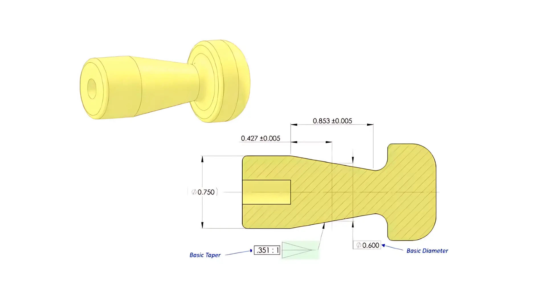
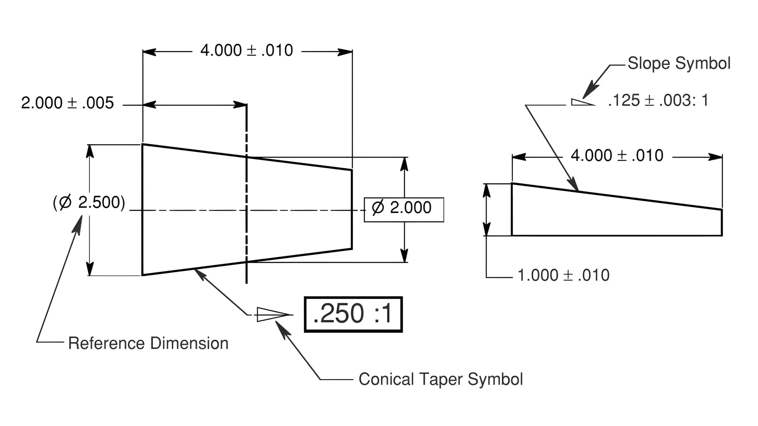
    In GD&T, the conical taper symbol is applied to define the angle of a conical surface. Conical taper refers to the ratio of the diameter change to the length change as shown in the Figure 1.

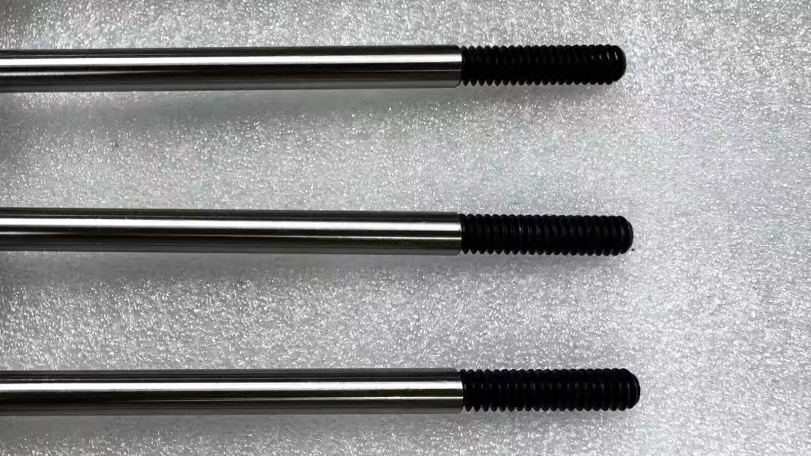
    For instant, a conical taper “1:20” for a tapered shaft means that for every 20 units of length along the shaft, the diameter is allowed to change by 1 unit.Conical Taper Example

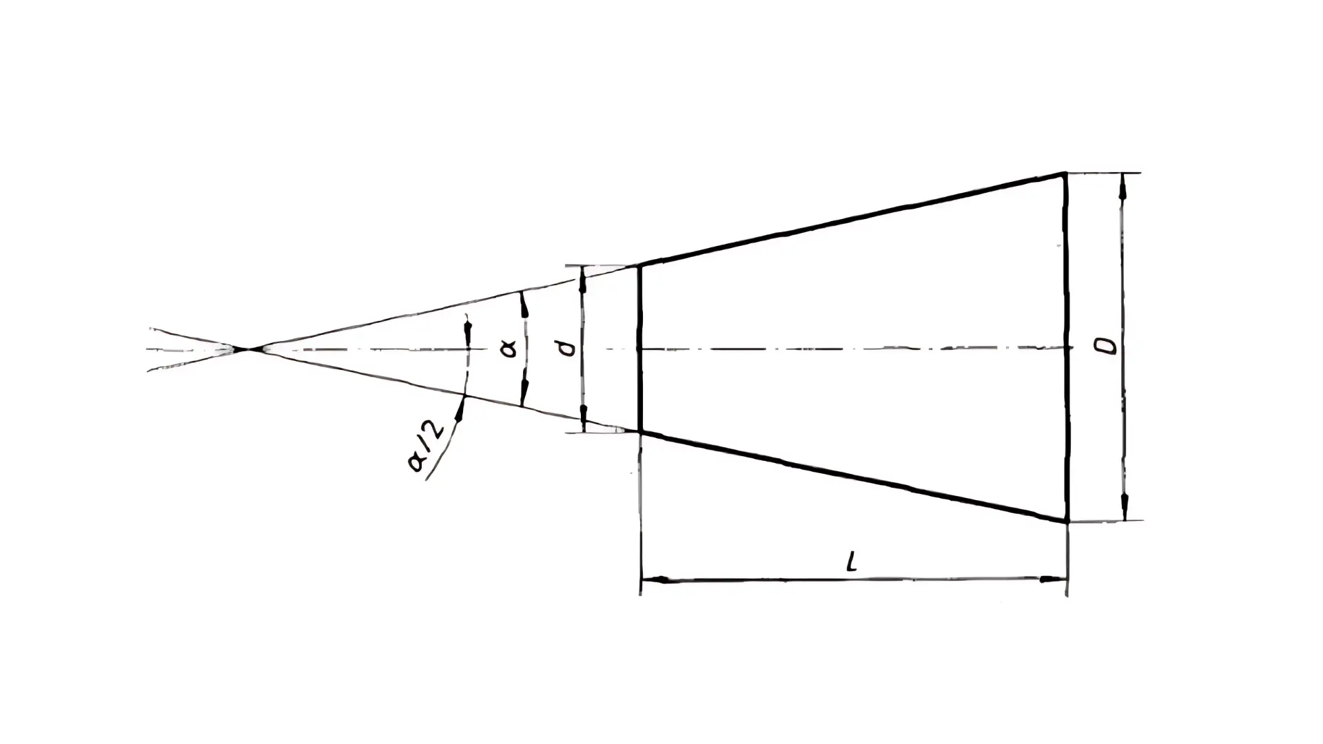
    And since GD&T conical taper is used to specify a ratio, its tolerance also controls the allowable deviation of the ratio.Conical Taper Formula

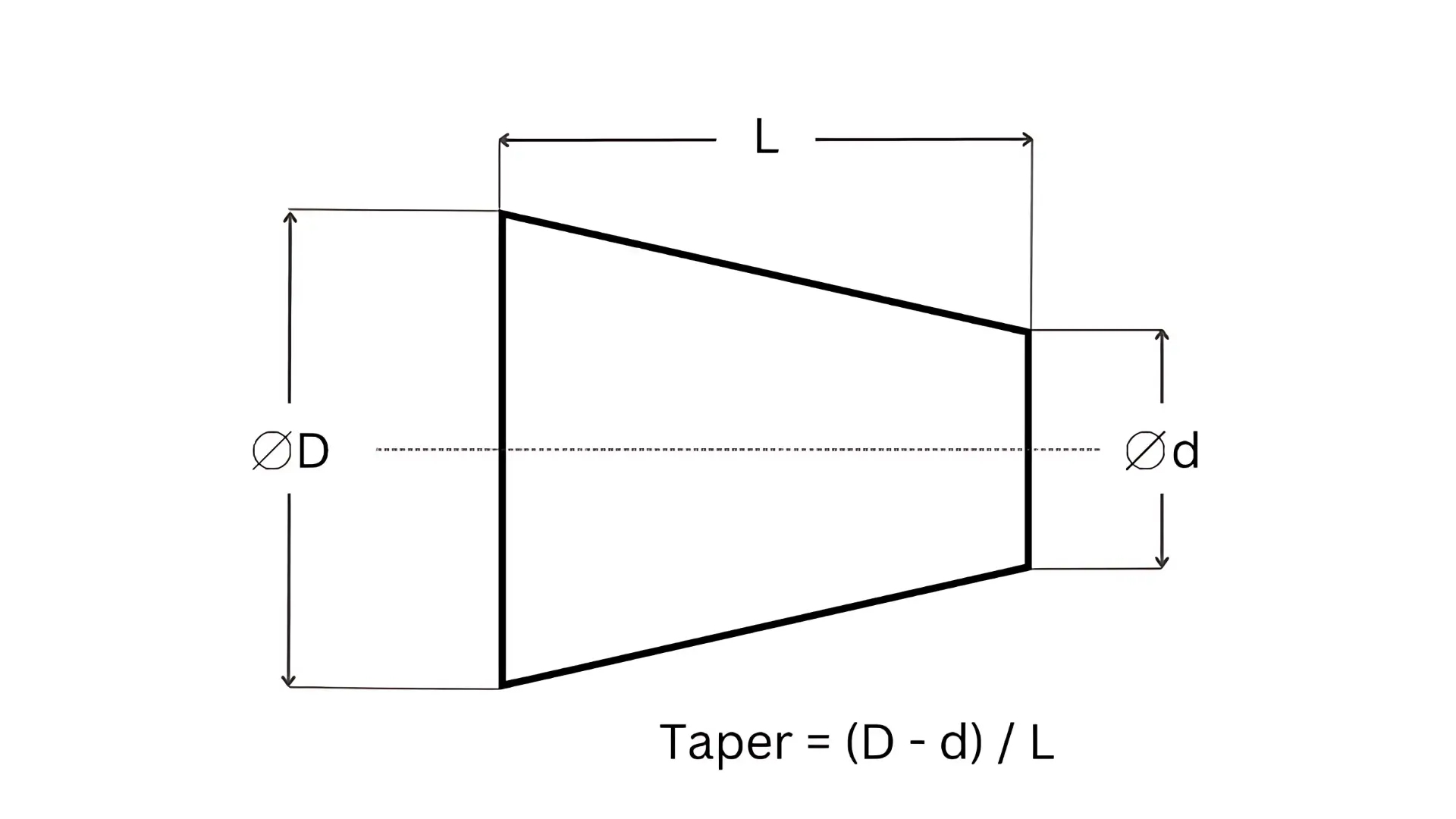
    For example, if “1:20 ±0.001” is indicated for the conical taper value and its tolerance, it means that the standard conical taper is 1:20 and the ratio is allowed to range from 1:19.999 to 1:20.001 during manufacture.

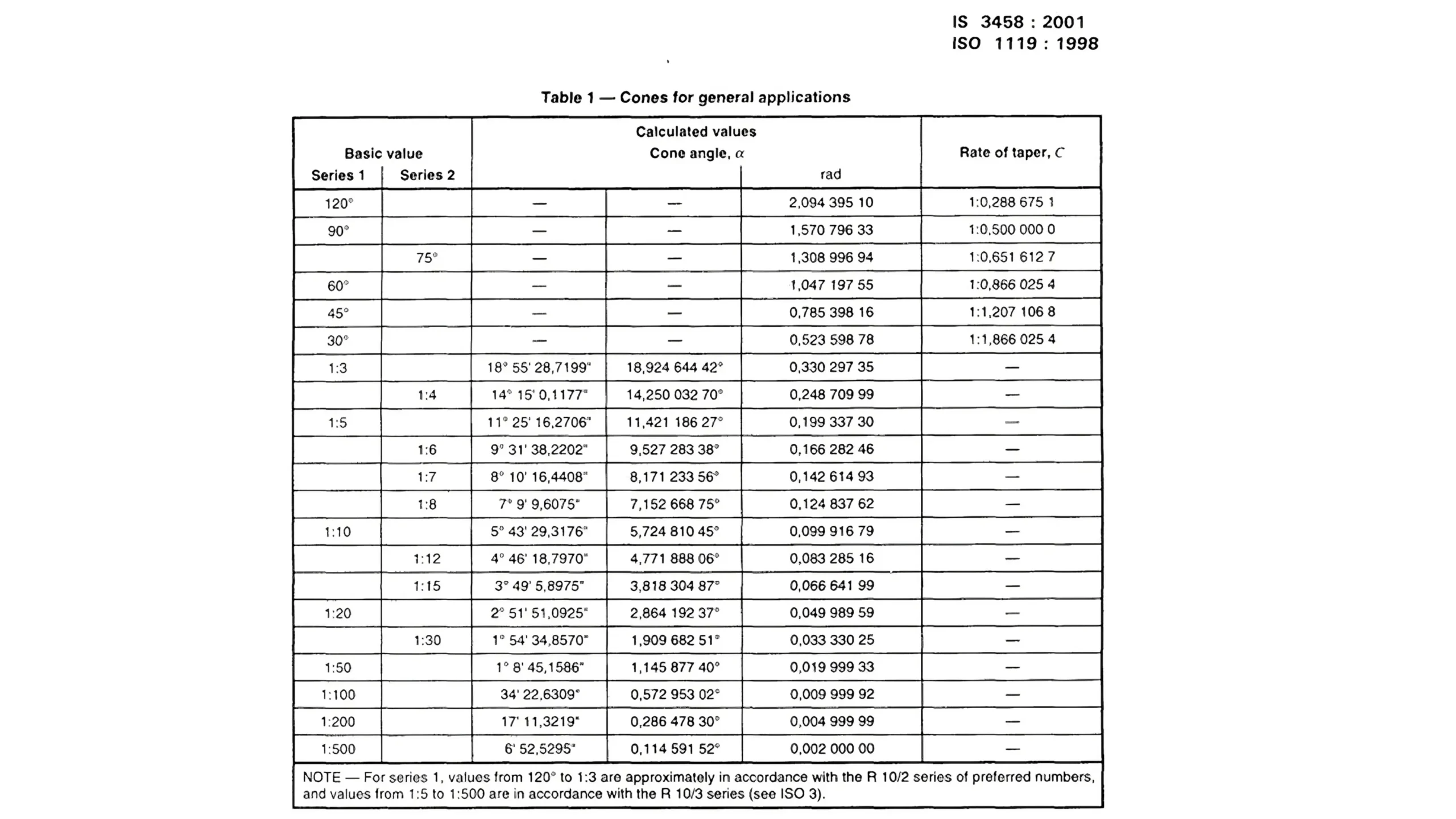
    What’s more, if the controlled parts are mating parts with assembly requirement, it is preferable to used standard conical taper systems such as Morse Taper or Metric Taper for control. Basic taper is allowed to be indicated without tolerance.

    And the usage of GD&T conical taper is usually combined with other dimensional and geometric tolerances such as diameter, angularity, and profile.

    2. How to Indicate GD&T Conical Taper Symbol?

    The GD&T Conical taper symbol is shown as a sideways triangle run through by a datum line.

    The symbol’s pointing direction must be consistent with that of the controlled conical feature’s circular cone shown on the engineering drawing.

    However, regardless of the actual direction of the cone shown on the drawing, the vertical leg of GD&T conical taper symbol is always represented on the left side.

    In addition, the symbol’s datum line should be connected with the cone’s profile line through an arrow line. Meanwhile, the datum line must be parallel with the cone’s axis.

    The dimension value, indicating the taper ratio, should be placed next to the symbol with the tolerance beside(if required).

    3. How to Measure GD&T Conical Taper?

    The main methods to measure GD&T conical taper are as follows:

    • Taper Gauge

    Taper gauges are the most basic and rapid detection method for GD&T conical taper measurement, suitable for qualitative judgement of whether the taper is qualified in mass production.

    By using a standard taper gauge to match the measured taper (plug gauge for internal cones and ring gauge for external cones), the conformance is determined by observing the gap between the conical surface and the gauge body (qualified if the gap is uniform and smaller than the allowable value).

    Steps:

    1. Clean the measured conical surface and the working surface of the taper gauge;
    2. Slowly fit the taper gauge to the measured conical surface with slight pressure;
    3. Check the gap with a feeler gauge or light (judged as qualified if the gap is uniform and within the tolerance range).

    Features:

    It is simple and efficient to measure GD&T conical taper through taper gauges. And they are suitable for medium-low precision and mass-produced parts, such as pipe interfaces and tool taper shanks.

    But taper gauges can only be able to judge conformance without obtaining specific taper values.

    • Projector Measurement

    It is suitable for small and medium-sized, medium-precision conical parts, such as mold conical surfaces, small shaft taper segments.

    With strong intuition and medium measuring precision (usually ±0.01°~±0.1°), projectors are suitable for conical parts with complex contours.

    Steps:

    1. Calibrate the projector to ensure accurate projection magnification;
    2. Fix the part and adjust the focal length to clearly project the conical contour onto the screen;
    3. Mark the diameter endpoints and length datum of the two ends of the cone on the projection screen, and read Dd, and L;
    4. Substitute into the formula to calculate the taper and compare with the drawing tolerance.
    • Coordinate Measuring Machine

    Coordinate Measuring Machines can directly fit the conical surface and output the taper value.

    With extremely high precision, they are suitable for complex conical parts(such as engine cone shafts and precision mold conical surfaces) and taper measurement with datum requirements in GD&T.

    However, the equipment cost is high and requires professional operation.

    Steps:

    1. Establish a measurement coordinate system (set datum planes/axes according to drawing datums, such as through the bottom surface or end face);
    2. Use the probe to collect points on the conical surface at different heights (evenly distributed in the circumferential and length directions);
    3. The software fits the conical surface and automatically calculates the taper value;
    4. Compare with the taper tolerance on the drawing to judge conformance.

    4. Morse Taper VS Metric Taper

    Morse Taper and Metric Taper are two kinds of different standard conical taper systems. As an imperial conical taper standard system, the former is popularly used in England and America while the latter is particularly used in ISO, GB and DIN as a kind of international standard system.

    The core difference between Morse Taper and Metric Taper lies in their division of conical taper ratio and model series.

    For Morse Taper, the taper ratio is not fixed. Tapers of different models are different to some extent, about 1:19.212 to 1:20.027.

    And Morse Taper has eight kinds of models(0-7 sizes). Larger number corresponds to a larger size(larger diameter and length). For example, the NO. 0 size’s diameter of the taper’s big end is about 9.045 mm and the length is about 59.5 mm.

    Therefore, indication of Morse Taper directly shows with model size, like MT3(Morse Taper 3).

    In addition, as the conical taper of Morse Taper is small to some extent, the self-locking performance after assembled is good and suitable for static or low-speed assembly.

    For Metric Taper, the taper ratio is fixed to 1:20. In other words, all models should follow this ratio. Models in Metric Taper are divided directly by their diameter dimensions with the lengths change according to ratio 1:20.

    Therefore, indication of Metric Taper show by taper ratio with diameter dimension.

    The self-locking performance of Metric Taper is as good as that of Morse Taper. And since models of Metric Taper are directly divided by their diameters, Metric Taper is dominant in standard design.

    As for applications, Morse Taper is mainly applied to assemblies of tapered tools such as drill bits, milling arbors and lathe centers.

    The largest advantage of Morse Taper is that its model series mostly cover all of the common tool sizes and its self-locking performance is suitable for manual assembly and disassembly.

    While Metric Taper is widely used in conical assemblies of general machinery components. Since the taper ratio is fixed to 1:20, it is more convenient for dimensional calculation during design and manufacture.

    And Metric Taper is compatible with Metric Dimension System. Therefore, Metric Taper is suitable for mass production of standardized components.

    FeatureMorse TaperMetric Taper
    Typical UsesDrill bits, milling arbors, lathe centersCNC machine tools, machining center spindles
    AdvantagesSelf-locking, high compatibility with legacy equipmentHigh precision, better standardization for automation
    LimitationsLimited size range, especially for large tapersMay require adapters in traditional machines

    5. Conclusion

    As an important symbol in GD&T, conical taper plays a critical role in controlling the taper of conical features and thus ensuring proper precision and assembly.

    For more detailed applications, refer to the ASME Y14.5 standard or specialized GD&T handbooks.

    6. Reference

    Below shows an international standard for a series of cones or conical taper, appliable only for plain conical surfaces(excluding prismatic pieces, taper threads, bevel gears, etc.).

    conical taper international standard

    Other Articles You Might Enjoy

    GD&T Profile of a Line

    Profile of a Line

    GD&T profile of a line is to control the deviation of any actual linear element on surfaces, like straight lines, curved lines or lines on cross-section planes from their exactly ideal profile.

    GD&T Symmetry

    GD&T Symmetry

    Symmetry controls that the Median Plane of a non-rotating feature must be aligned with the Datum Center Plane. It has been removed from the standard GD&T toolbox.

    Concentricity in GD&T

    GD&T Concentricity

    Concentricity is a position tolerance that measures the degree to which the center points of circular features (cylinders, cones, spheres) coincide relative to a shared datum axis or point.

    GD&T symbols True Position

    GD&T True Position

    True position GD&T is one of the position symbols in GD&T that is used to control the positional accuracy of a feature of size, such as a hole, shaft or slot, with respect to the datum coordinate system.

    Let's get your projects started, together!

    Get custom parts machined in high quality, delivery on time.