Home » Blog » Symmetry in GD&T

Symmetry in GD&T

By Lucas Lo | Updated: May 14, 2025

Table of Contents

    As we all know, symmetry is a fundamental concept in GD&T, used to control the alignment of features relative to a central plane.

    Symmetry ensures that corresponding elements on both sides of the datum plane are mirror images, which is crucial for maintaining balanced structure and proper assembly, especially for symmetrical parts requiring uniform load-bearing and consistent appearance, like mechanical casings or precision components.

    1. What is symmetry in GD&T?

    Core Definition:

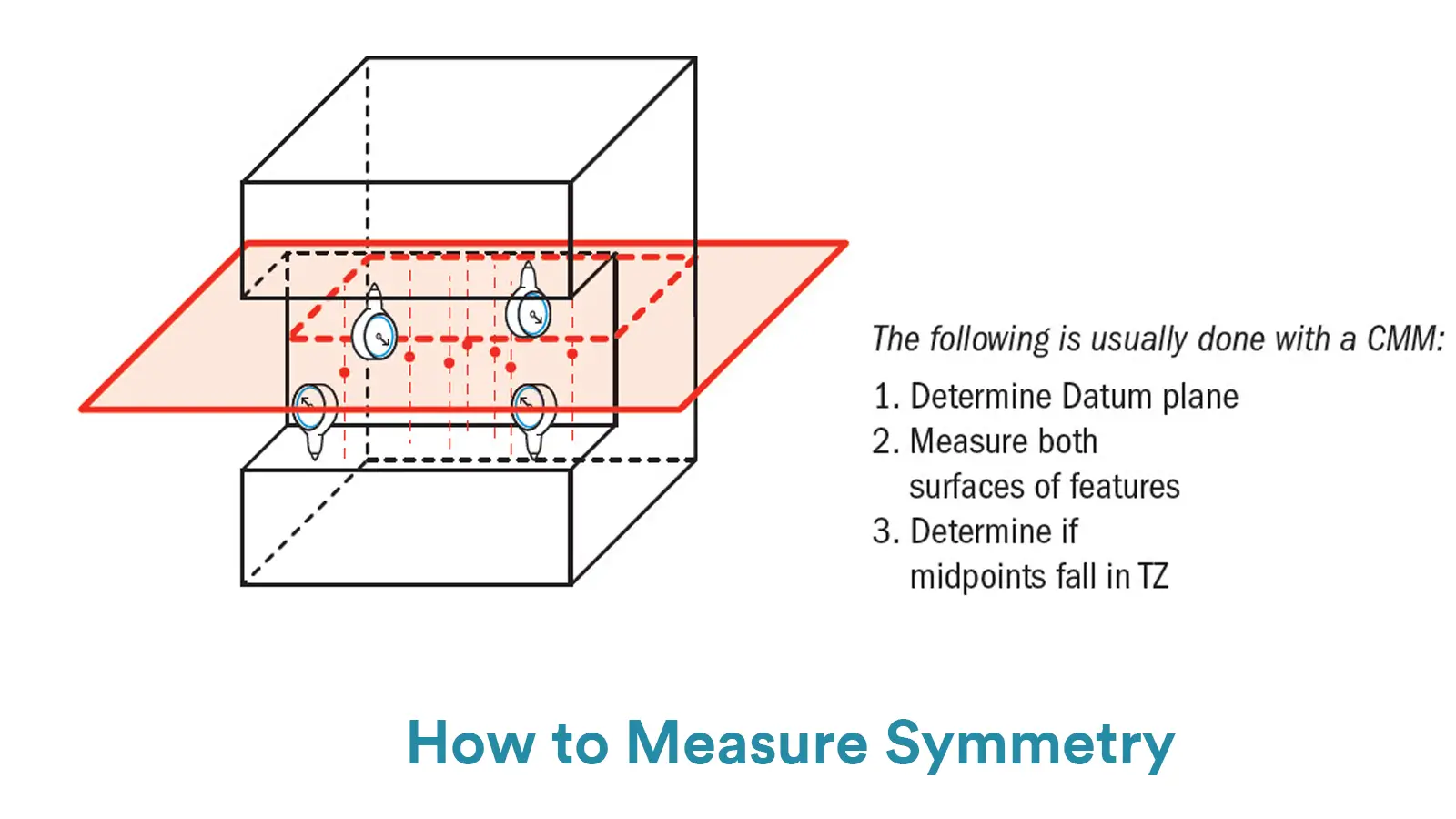
    Symmetry controls that the Median Plane of a non-rotating feature (e.g., keyway, boss, planar group) must be aligned with the Datum Center Plane.

    In essence, the tolerance zone consists of the area between two parallel planes arranged symmetrically on either side of the datum plane.GD&T Symmetry

    Application Scenarios:

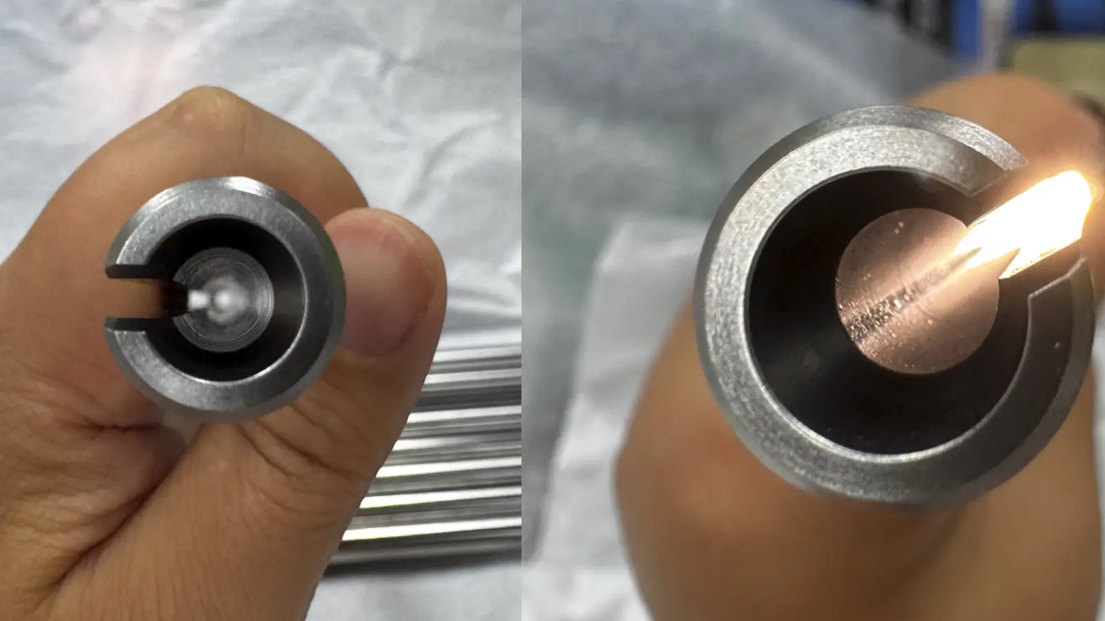
    Mating of keyways to shafts.

    Symmetrically distributed groups of mounting holes.

    Mold design with symmetrical parting surfaces.

    2. What is the symbol for symmetry?

    Old symbol (ASME Y14.5-2009): ⏀, labeled in the feature control box, pointing to the datum plane.

    Modern alternative (after ASME Y14.5-2018):

    Annotate with a positional tolerance (Ⓟ) and include a note indicating “symmetrically distributed”.

    Example:

    Ⓟ0.1Ⓜ A B (symmetric)  

    Datum A: Part center plane  


    3. What is the Role of the Symmetry Symbol?

    Transmission of design intent:

    It is clearly stipulated that the center plane of the feature must be precisely symmetrical with respect to the datum to prevent assembly interference.

    Production and inspection basis:

    Define the allowable range of symmetry deviation (e.g. ±0.05mm); provide tolerance parameters for CMM programming and function checker design.

    4. How to mark symmetry on drawings?

    Conventional labeling (deprecated):

    ⏀ 0.1 | A  

    Modern labeling (recommended):

    Step1: Regulate the feature by using the position degree (Ⓟ).

    Step2: Put a “SYMMETRICAL” note in the tolerance box or the comment section.

    Example drawing:

    Ⓟ0.1Ⓜ A B (symmetrical)  

    Datum A: The mid – plane of the part (determined by features X and Y) Be aware:

    The datum plane must be clear and measurable, e.g. established by two parallel surfaces.

    Avoid rotary features (e.g. cylinders) and use symmetry control.

    5. How is GD&T symmetry measured?

    -Coordinate Measuring Machine (CMM) method:

    Step 1: Examine and scan all the relevant surfaces of the feature (like the two sides of a keyway).

    Step 2: Use the software to determine the mid-plane of the feature.

    Step 3: Determine the greatest distance by which the center plane deviates from the reference plane.

    Judgment criteria: deviation value ≤ tolerance value (e.g. 0.1mm).

    -Functional gage method:

    Gauge design: manufacture go – no – go gauges that fit the theoretical symmetrical contour precisely.

    Operation procedure:

    Align the part datum with the gage datum;

    The through-gauge should be able to pass through the feature without resistance, the stop-gauge should not.

    -Alternative (Positional Degree Verification):

    Measure the real – world position of the feature and confirm that it falls within the positional tolerance band. Symmetrically distributing the tolerance bands is a crucial prerequisite.

    How to Measure Symmetry

    6. Why is Symmetry Important?

    Assembly compatibility:

    Symmetry in the keyway ensures a proper and precise connection between the shaft and the gear, preventing one-sided wear.

    Machining efficiency:

    Symmetrical features allow the use of mirrored toolpaths (e.g. G51.1), reducing programming effort by 50%.

    Cost Control:

    Highly symmetrical parts reduce rework and minimize scrap (especially of valuable materials).

    7. How can symmetry machining problems be solved?

    To solve the symmetry machining problem, we can start from the following aspects:

    -Process and equipment: reasonable design of the machining process, the use of high-precision equipment and appropriate tooling to ensure the basic accuracy of processing.

    -Clamping and positioning: accurate clamping with special fixtures, multiple calibration and positioning, to avoid displacement and deformation in the processing of parts.

    -Detection and compensation: real-time monitoring with the help of online detection system, automatic adjustment of tools or parameters to compensate for the error.

    -Programming and Parameters: Accurately write the CNC program, cleverly use the mirror and other functions, and reasonably set the cutting speed and other machining parameters.

    -Personnel management: Improve operator skills, implement strict quality control, and analyze and refine regular sampling processes.

    8. Why Was Symmetry Removed from GD&T?

    The key factors that led to the removal of symmetry from GD&T in the 2018 version of ASME Y14.5 are presented below:

    -Limited functionality and replaceable: Its functions are limited, and position tolerances can mostly meet design requirements.

    -Difficult to measure: The tolerance zone of symmetry is a virtual plane, lacking efficient measurement methods, with complex operation and low accuracy.

    -Prone to misuse: In practice, the symmetry symbol is easily misused, while position tolerances have clearer definitions and fewer misunderstandings.

    9. What are the future challenges for symmetry?

    Challenges:

    Symmetry measurement of miniature parts: detection equipment for nanoscale symmetry deviations is costly.

    Symmetry control in composite materials: Processing anisotropic materials results in unstable symmetry.

    Technology Trends:

    AI-driven symmetry prediction:

    Machine learning analyzes how machining parameters relate to symmetry deviations and promptly adapts the toolpaths.

    Example: Siemens Edge AI dynamically compensates for thermal deformation during machining.

    Digital twins and virtual inspection:

    Simulation of symmetry deviations through virtual models to optimize pre-machining process design.

    10. Conclusion

    Although the symmetry symbol has been removed from the standard GD&T toolbox, the principle of symmetry continues to play a vital role in precision manufacturing.

    With positional tolerance, advanced machining strategies, and intelligent inspection methods, engineers can still maintain symmetry where needed. Future development should focus on addressing symmetry challenges in advanced materials and micro-/nano-scale manufacturing.

    Lucas

    Lucas is a technical writer at ECOREPRAP. He has eight years of CNC programming and operating experience, including five-axis programming. He also spent three years in CNC engineering, quoting, design, and project management. Lucas holds an associate degree in mold design and has self-taught knowledge in materials science. He’s a lifelong learner who loves sharing his expertise.

    Learn More about Lucas.

    Let's get your projects started, together!

    Get custom parts machined in high quality, delivery on time.