The indications of datum targets are different from that of datums. It is important to pinpoint the target position accurately and indicate the crucial information of the datum target’s type.
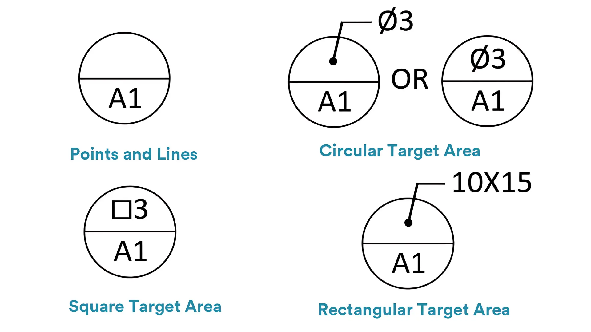
The datum target symbol is a circle with a horizonal line inside at the half to divide it into two even portions.
The lower portion contains a letter with a number right beside. The letter is associated with the datum which the datum target locates on. And the number is sequential to distinguish each datum target, but not related to priority. However, as we all know, letters A, B, and C are sorted by priorities.
The utter portion is relative to the dimension of the datum target. If the datum target is a point or a line, is it left blank. If the datum target is a limited area, the utter portion will contain the shape and size information of the area.
If the area is a circle, the diameter size will be contained inside the utter half with a diameter symbol left, or will be pointed to the utter half by a bent line.
If the area is a rectangular target area, the side length will be pointed to the utter portion, usually with the width left and the length right.
If the area is a square target area, the utter portion will contain a square symbol left and the side length right.
Datum targets are indicated on engineering drawings by datum target radial lines and different indicational symbols.
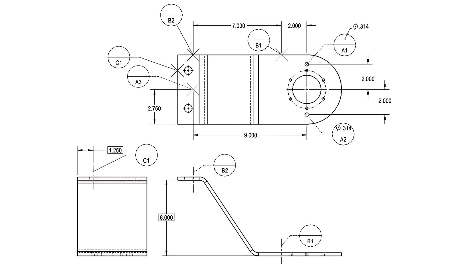
Datum targets are usually connected with a radial line that points to the datum feature. Datum target radial lines are either solid or dashed.
If the line is solid, the datum target is on the drawing side of the feature. While a dashed line suggests that the datum target is on the opposite side of the drawing.
Just as the datum target “A3” above shows, a datum target point is identified on an engineering drawing by its X-shaped symbol. The single point where a X-shaped symbol locates on refers to the contacting position between the datum simulator and the part.
And to locate the point accurately, a datum target point will be dimensioned directly in a direct view of the surface. If there is no direct view, the point will be dimensionally located on two adjacent views.
The datum targets B1, B2, and C1 above are all datum target lines. The indicational symbol of datum target lines is similar to that of datum target points, also a X-shaped symbol.
The X-shaped symbol is indicated on the drawing to show the line’s location on the part. Furthermore, the datum target line will also be indicated on another view by the dimensionally located dotted line to accurately show the line contacting position between the datum simulator and the part.
What’s more, datum target lines would be indicated commonly by the edge of a cylindrical gauge pin. And if required, the length of the line can also be indicated on the drawing.
The datum targets A1 and A2 above are both datum target areas. Usually, datum target areas are indicated by crosshatched area on engineering drawings.
If the datum target area is a circle, then the crosshatched area is also a circle. If the datum target area rectangular, then then crosshatched area is rectangular.
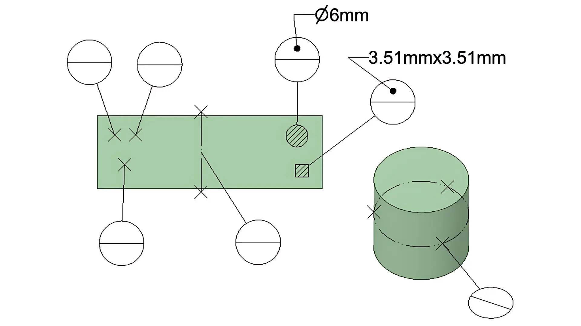
As we have explained above, an irregular surface of a feature cannot be used as a datum as a whole. In such a case, datum targets are applied to establish a datum reference frame with 3-2-1 location method.
A datum reference frame usually has six degrees of freedom. They are respectively linear translations in the X, Y and Z axes, and rotations around the three axes. By constraining the part to datum targets, the 3-2-1 method can gradually eliminate these degrees of freedom and then accurately fix the feature location.
Here we will take an entire surface of an automotive part as an example.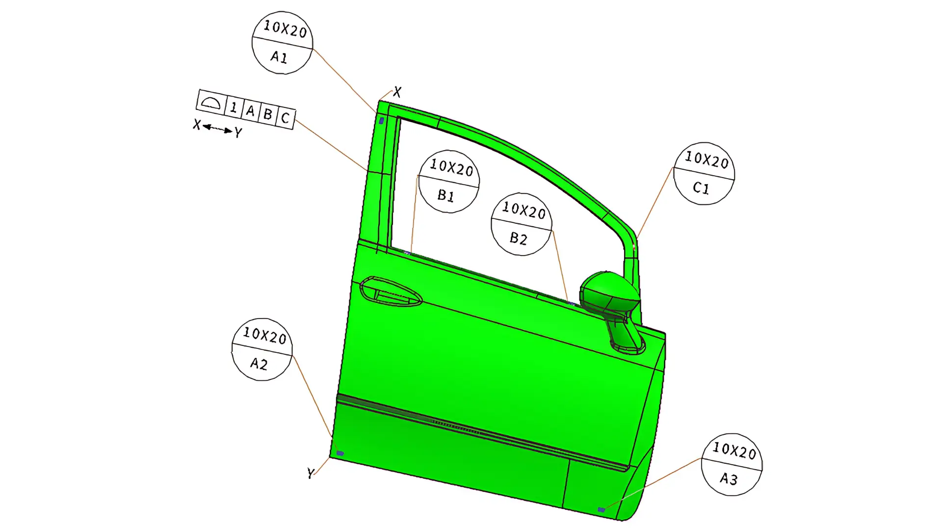
The first step to establish the datum reference frame is to select the primary datum and choose 3 positions for datum targets on the datum.
Usually, the largest surface of the part would be selected as the primary datum. And the 3 datum targets would be located as far apart as possible for stability.
In this example, since the surface is large enough, we use 3 datum target areas for simulated datums. They are datum targets A1,A2 and A3 in Figure 1.
Therefore, the translation in the Z-axis and rotations around the X-axis and Y-axis are eliminated by these three datum targets on the primary surface.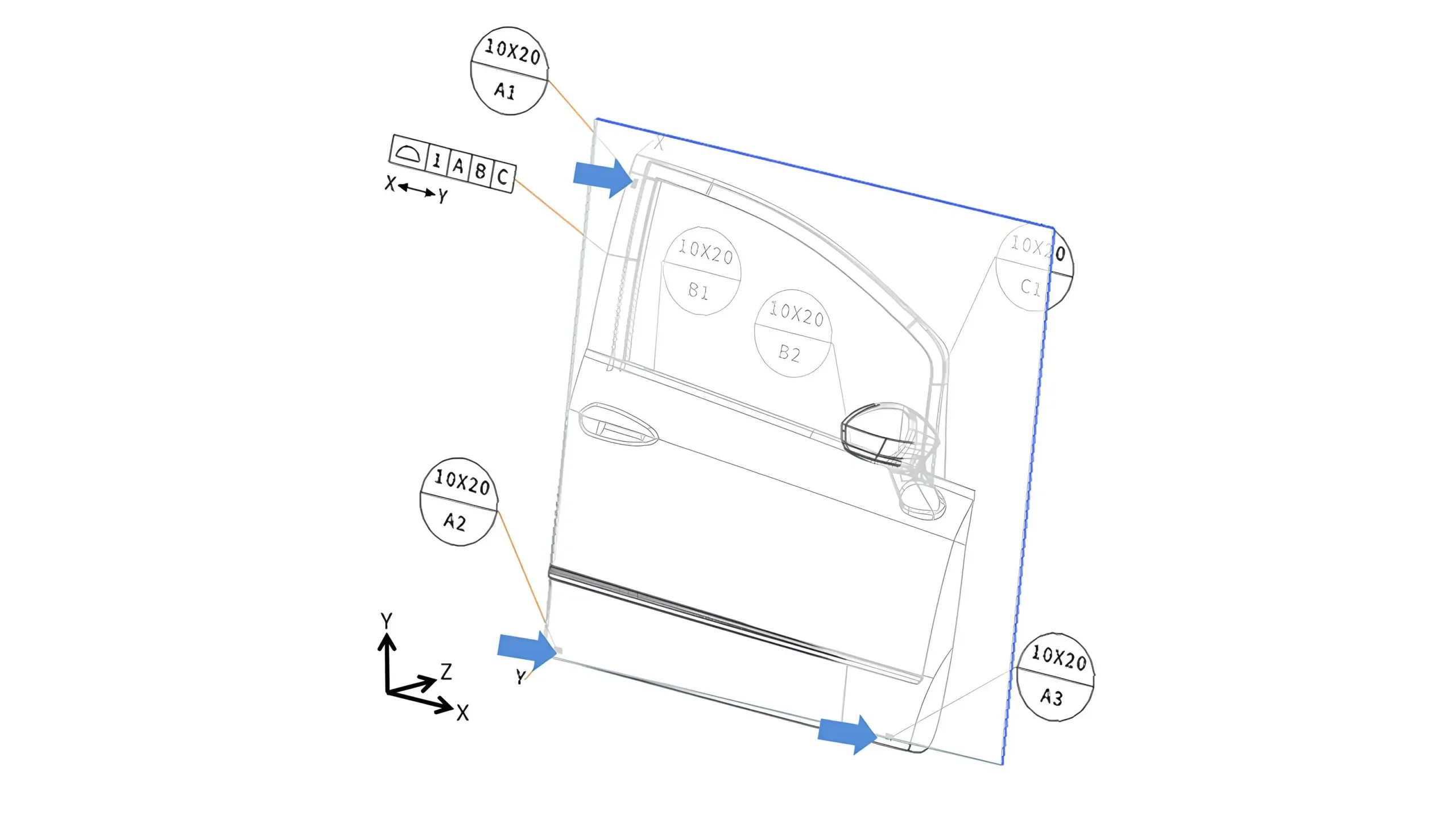
Primary datum plane defined by three datum target areas (A1, A2, A3)
And then the second largest surface which is perpendicular to the primary datum would be select as the secondary datum usually. At the same time, two datum targets are to be selected on the secondary datum.
In this case the two datum targets are B1 and B2 in Figure 2, with which translation in the Y-axis and rotation around the Z-axis are eliminated.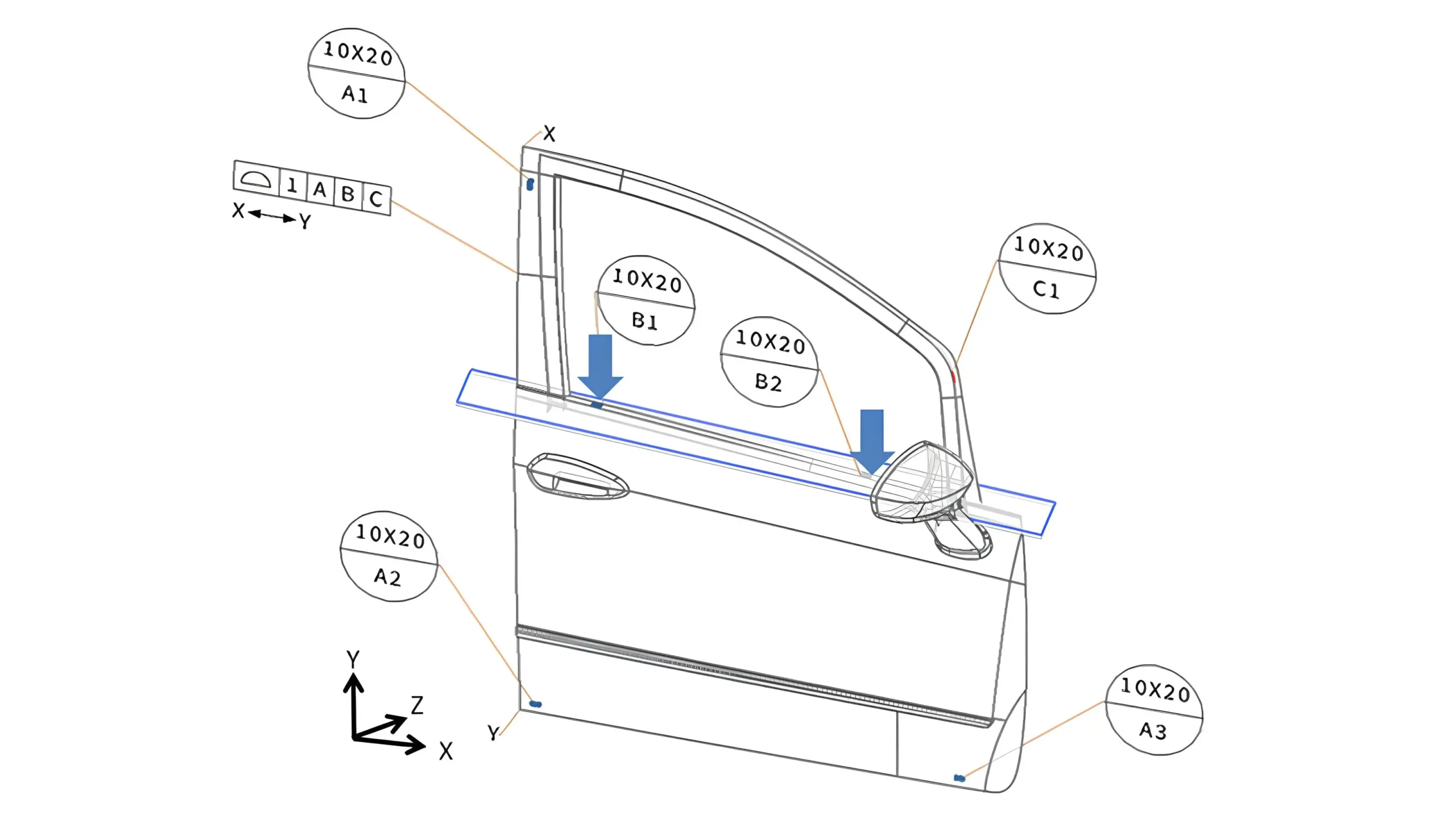
Finally, a surface which is perpendicular to both the primary and secondary datums would be selected as the tertiary datum, and just one datum target is required on the surface.
Datum target area C1 in the Figure 3 is the one in this example. It is used to eliminate the translation in the X-axis.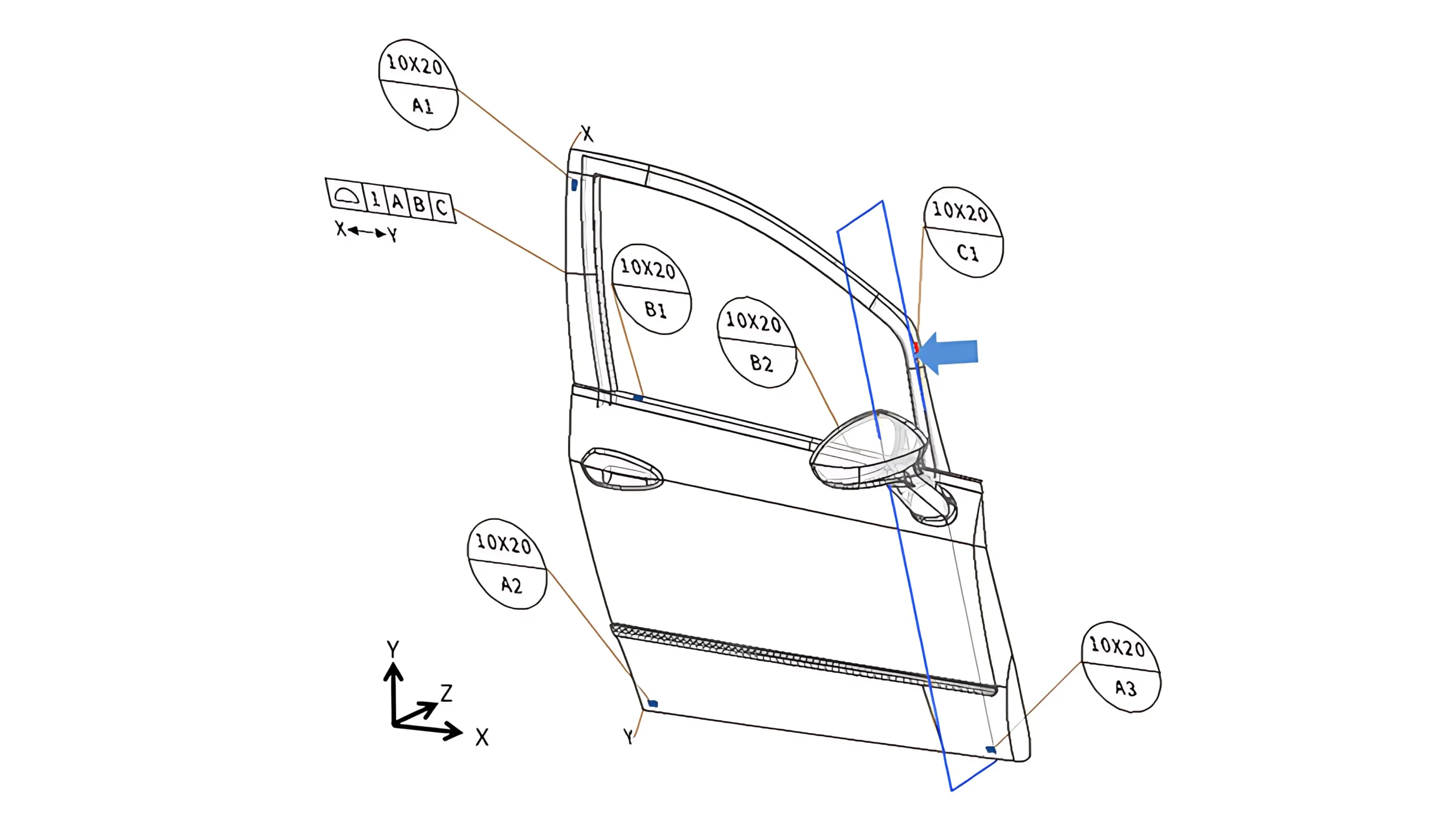

5-Axis CNC machining is a manufacturing process that uses computer numerical control systems to operate 5-axis CNC machines capable of moving a cutting tool or a workpiece along five distinct axes simultaneously.

China is the best country for CNC machining service considering cost, precision, logistic and other factors. Statistical data suggests that China emerges as the premier destination for CNC machining.

Selecting the right prototype manufacturing supplier in China is a critical decision that can significantly impact the success of your product development project.

Machining tolerances stand for the precision of manufacturing processes and products. The lower the values of machining tolerances are, the higher the accuracy level would be.