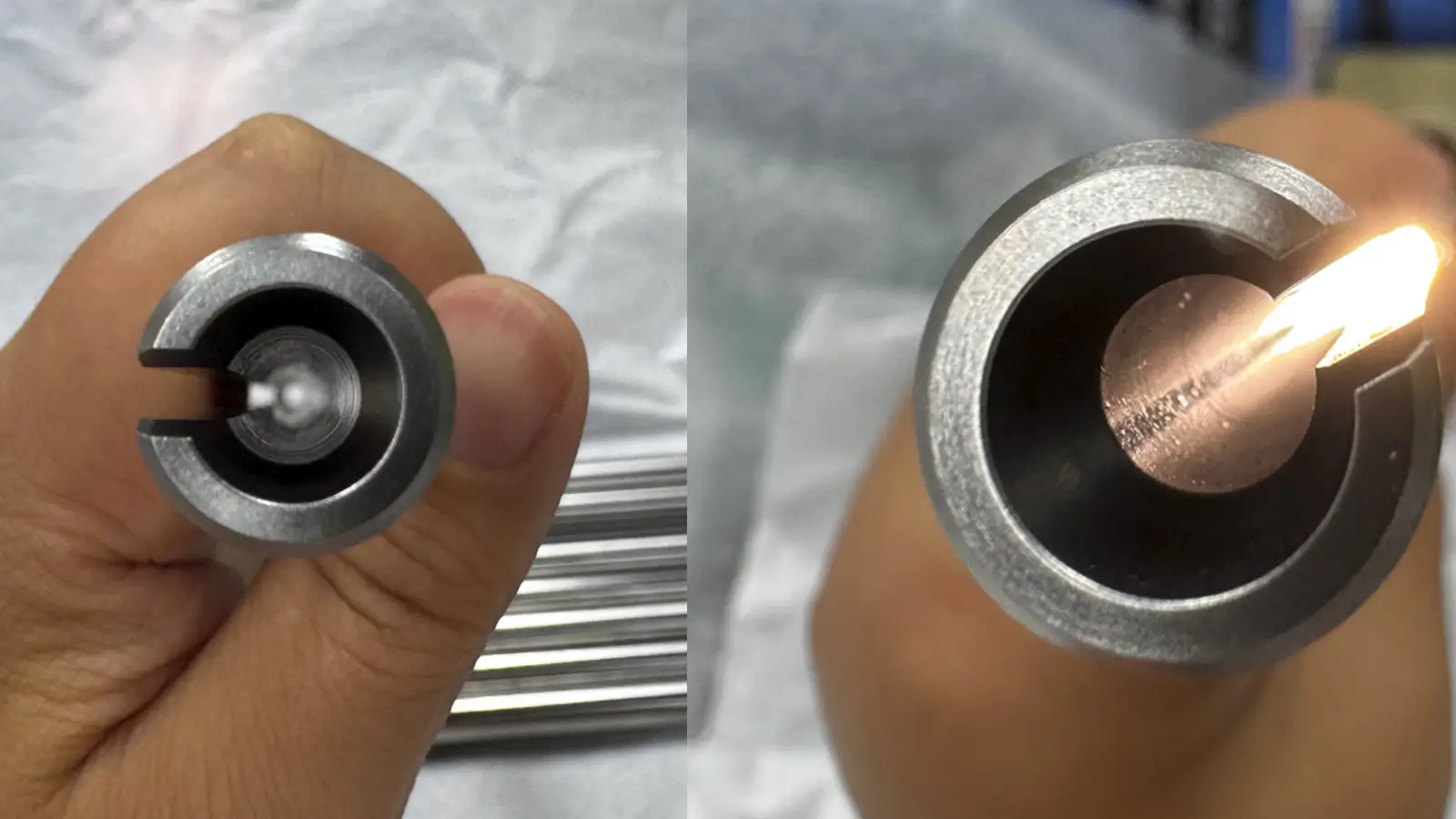
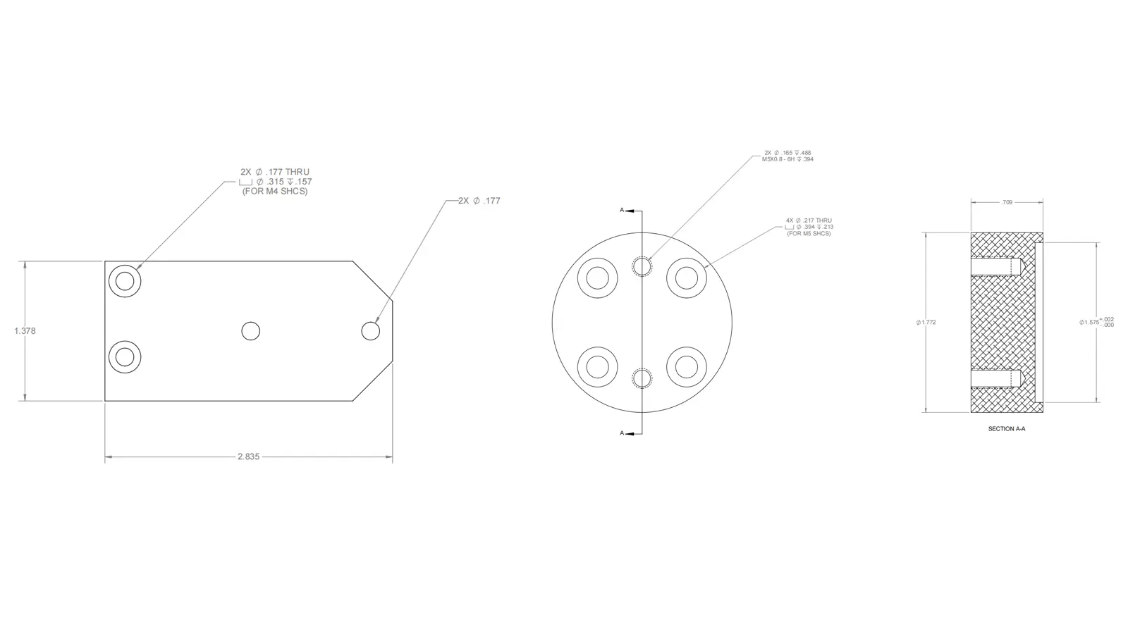

The diameter is present on every CNC drawing that includes holes or cylindrical features.
In CNC working shop, we use Vernier Caliper, Outside Micrometer,Inside Micrometer, CMM (Coordinate Measuring Machine) and Optical Comparator / Vision System to check the diameter based on different sturcture and tolerance requirement.
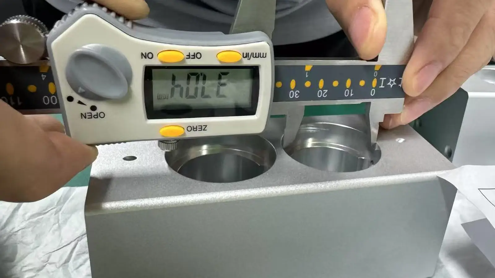
A vernier caliper is simple and easy-use to measure the outside and inside diameter, and depth.
It is a great tool for quick cheks with typical accuracy around ±0.02mm.
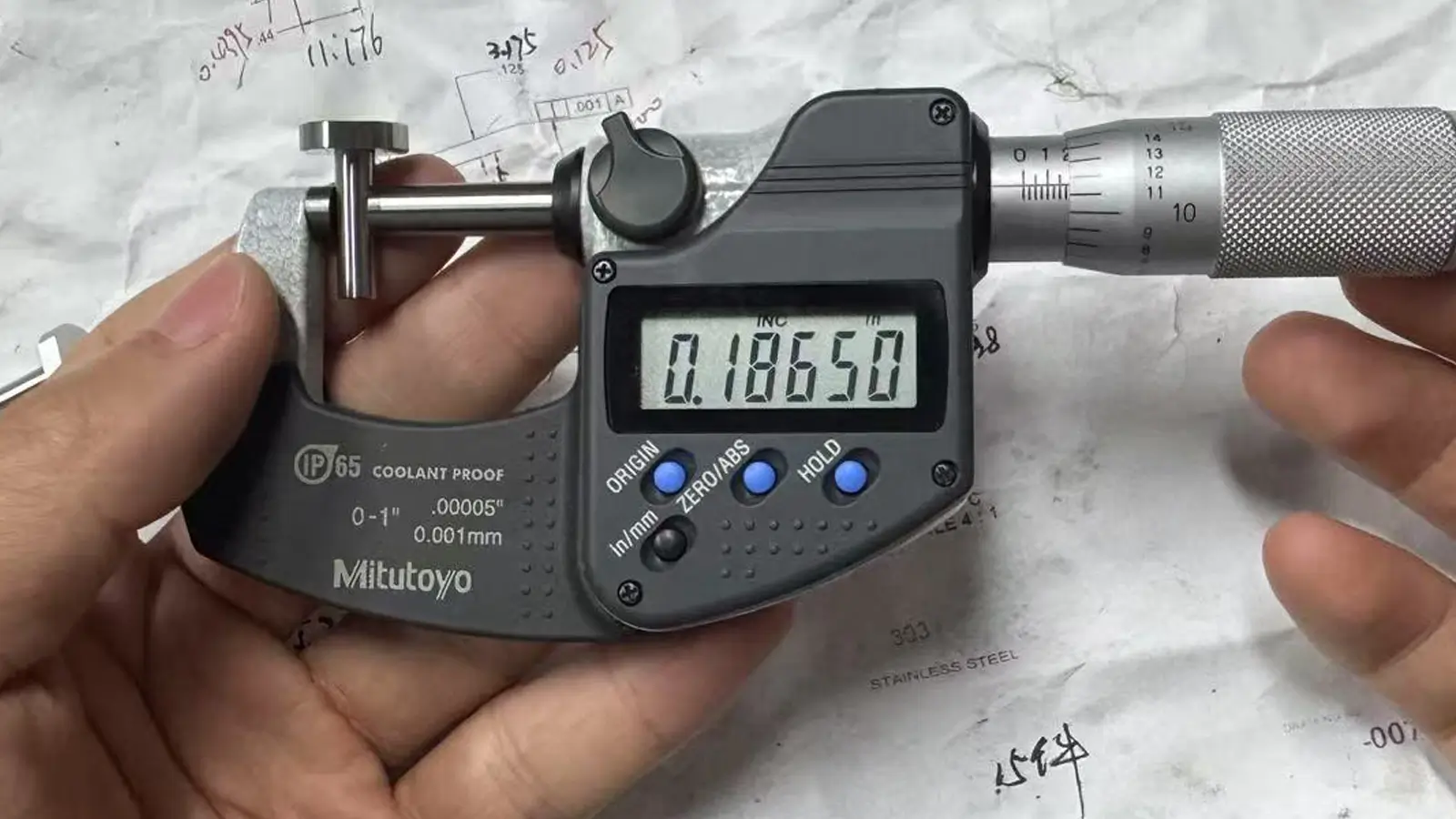
The outside micrometer is for precise measurement of external features like shafts and round pins.
Micrometers offer excellent accuracy—usually ±0.01mm or better—but they’re best suited for simple cylindrical shapes.
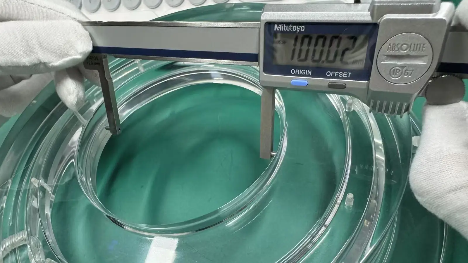
Like an outside micrometer, an inside micrometer is also for precise measurement, but for internal diameters of holes.
They’re ideal for medium to large holes where higher accuracy is needed.
A CMM can measure the diameter, center location, and even roundness.
It’s a highly automated, extremely accurate method (up to ±0.002mm), making it perfect for complex parts or when customers require full inspection reports.
These are non-contact tools that project or capture a magnified image of a part’s profile.
Optical compartor is ideal for small, thin-walled, or flexible parts, especially when contact tools like calipers and micrometers might distort them.
Optical systems are highly accurate—around ±0.005mm—and great for visual quality checks.
Comparison Table – Diameter Measurement Tools
| Tool | Accuracy | Contact / Non-Contact | Recommended Use | Key Features |
| Vernier Caliper | ±0.02 mm |  Contact Contact | General outside & inside diameters | Fast and portable |
| Outside Micrometer | ±0.01 mm ~ 0.001 mm | Contact | High-precision outside diameters | Stable and accurate |
| Inside Micrometer | ±0.01 mm ~ 0.003 mm | Contact | Precision internal diameters | Ideal for deep or large holes |
| CMM (Coordinate Measuring Machine) | ±0.002 mm | Contact (probe) | Tight-tolerance parts, report output | Auto-fitting and digital measurement |
| Optical Measuring System | ±0.005 mm ~ 0.001 mm |  Non-contact Non-contact | Small parts, transparent parts, software-compatible | Non-contact, image magnification |

5-Axis CNC machining is a manufacturing process that uses computer numerical control systems to operate 5-axis CNC machines capable of moving a cutting tool or a workpiece along five distinct axes simultaneously.

China is the best country for CNC machining service considering cost, precision, logistic and other factors. Statistical data suggests that China emerges as the premier destination for CNC machining.

Selecting the right prototype manufacturing supplier in China is a critical decision that can significantly impact the success of your product development project.

Machining tolerances stand for the precision of manufacturing processes and products. The lower the values of machining tolerances are, the higher the accuracy level would be.