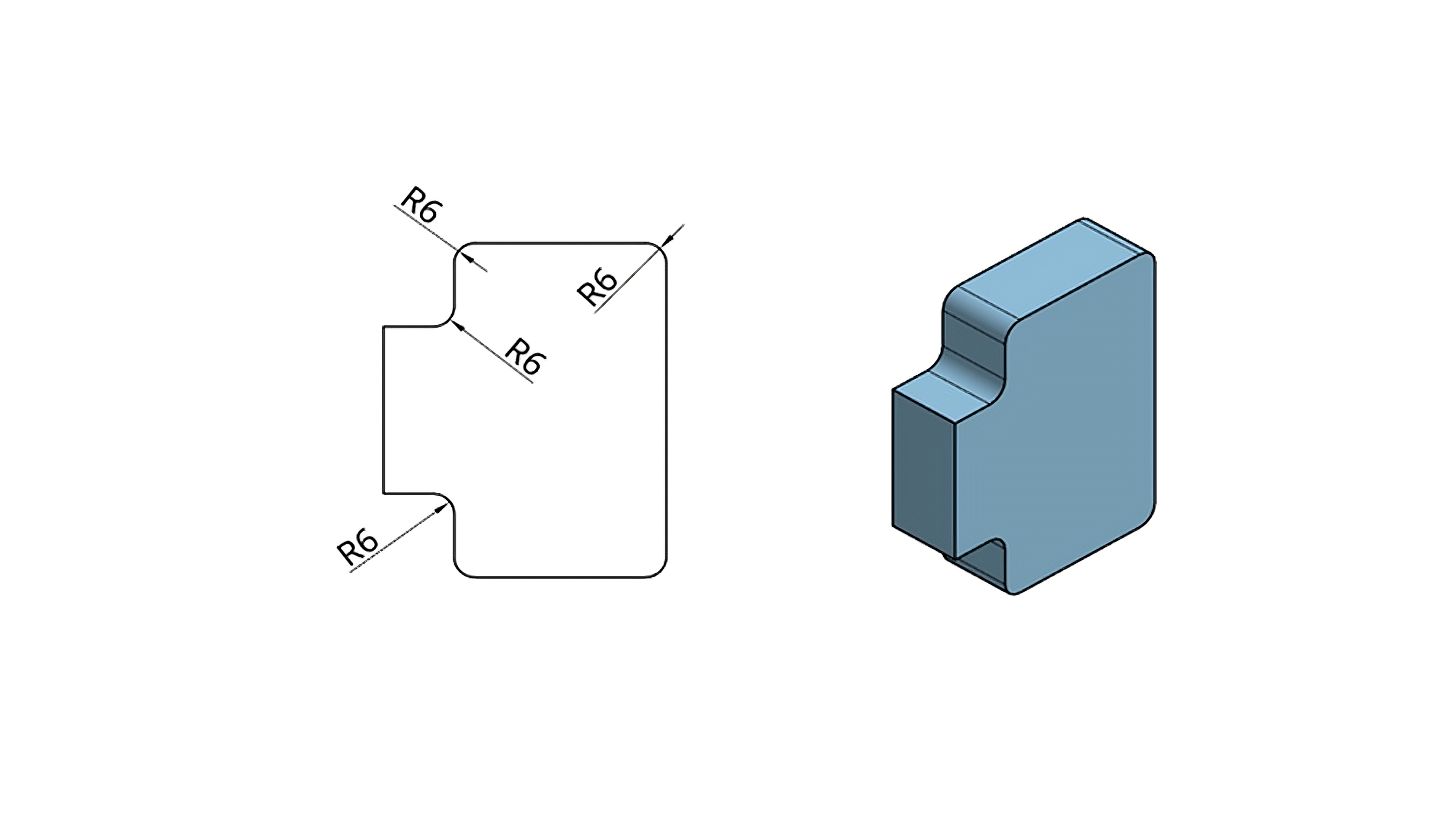
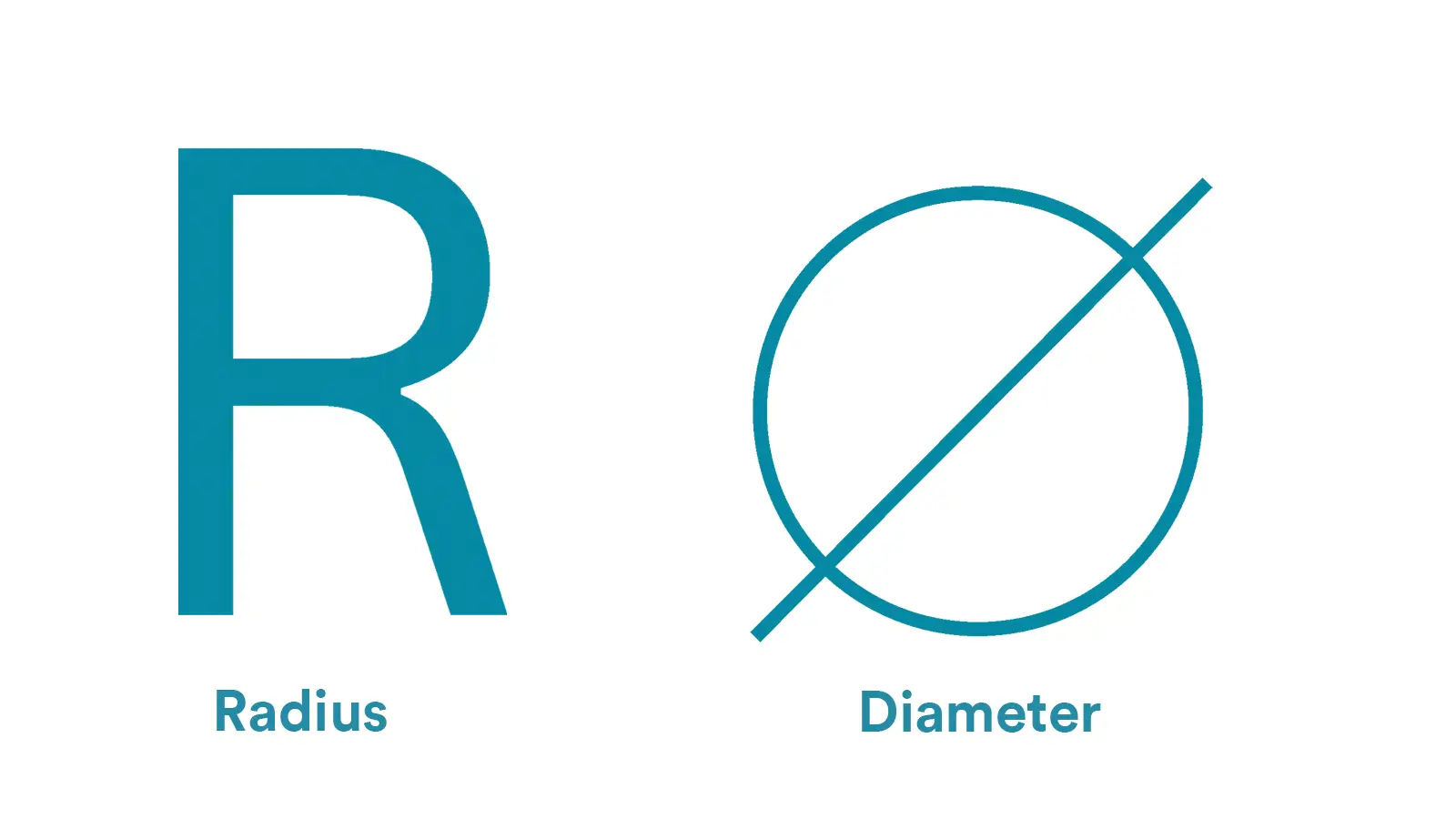
Different from the diameter’s symbol, the radius uses the capital letter R, which directly originates from the first letter of the English word “radius”. Specific rules are as follows:
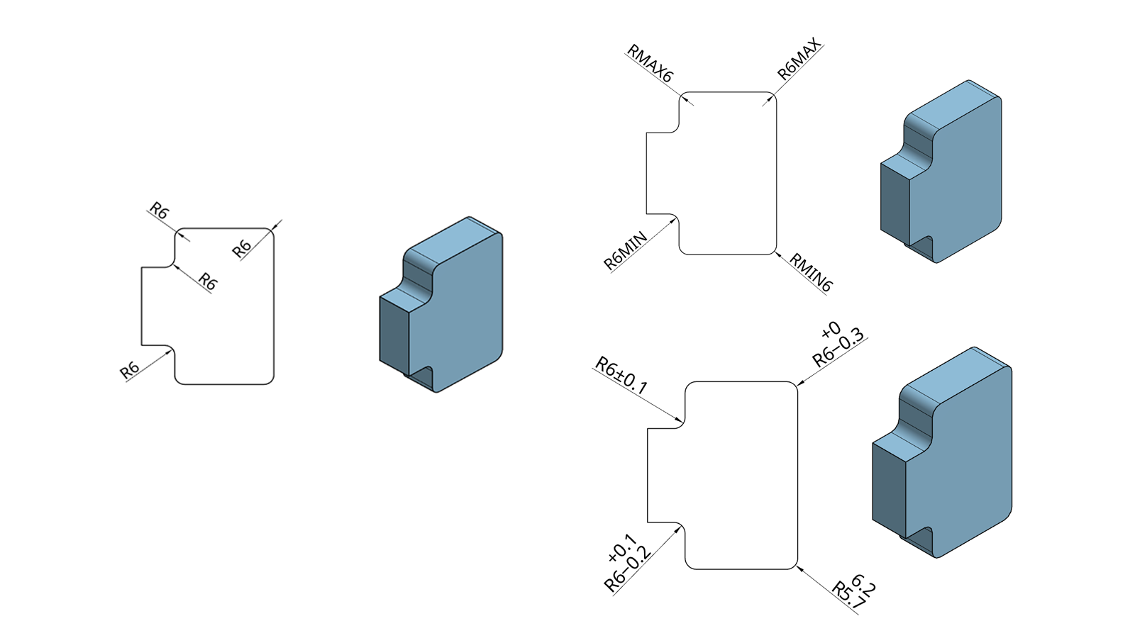
In engineering drawings, the marking of the radius symbol (R) usually needs to be combined with the type of arc feature (two-dimensional arc / three-dimensional spherical surface), dimensional accuracy, and reference association requirements, and is marked in a layered form.
The first row is the type and number of features of circular arcs as well as the dimensions and tolerance bands as follows:
-Symbol: Based on the features of circular arcs, it can be divided into two-dimensional circular arcs and three-dimensional spheres.
Two-dimensional arc: directly labeled R, if not specified, the default is two-dimensional arc.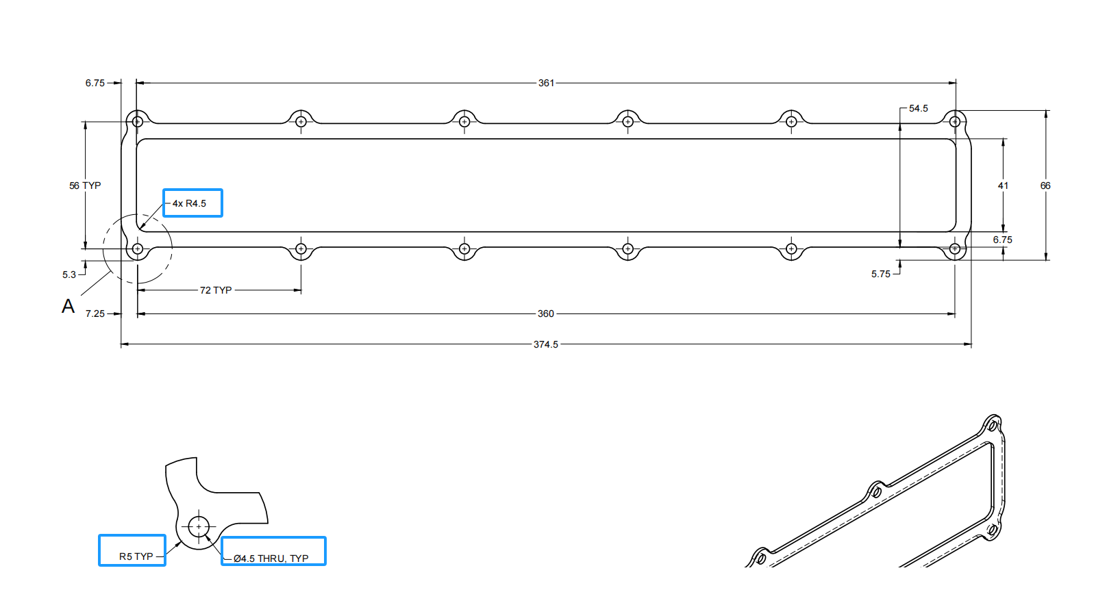
Three-dimensional spherical: labeled SR (Spherical Radius).
-Quantity: Multiple identical arcs: use “×” to connect the quantity and symbols, e.g. 6×R, indicating 6 arcs of the same radius.
-Basic size: directly label the radius value and unit, e.g. R15mm.
-Tolerance labeling: add the tolerance range after the value, e.g. R10 ± 0.1mm or R8mm +0.05/-0.03.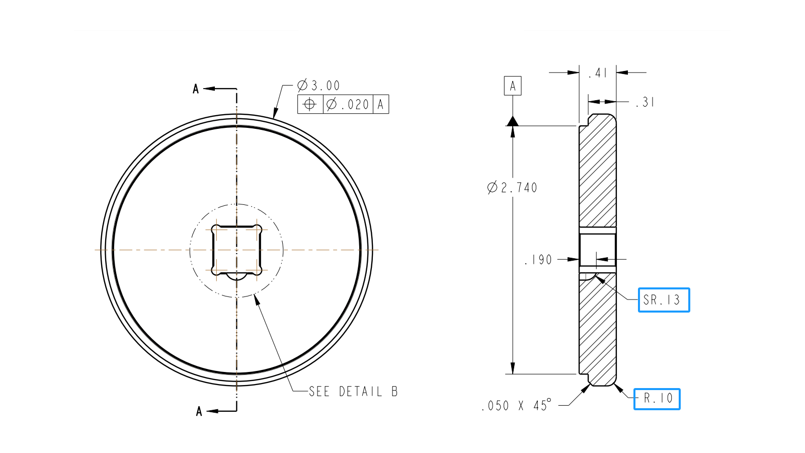
The second row of datum associations and geometric tolerances is as follows:
-Datum association
Symbol : Apply datum symbols (such as Ⓐ, Ⓑ) to specify the positioning reference of the arc.
Format: Use the datum symbol (e.g., R18mm Ⓐ) after the radius dimension to indicate a circular arc that is positioned with datum A as the center.
Geometric Tolerance (Shape Control)
Roundness/Contour: For controlling the arc’s shape accuracy, incorporate a geometric tolerance frame.
Control Radius (CR): If a smooth contour (no reverse curvature) is required, label CR instead of R, e.g. CR12mm.
| Scenario | Labeling Structure | Interpretation |
| Single 2D arc | R10mm | A 2D arc with a radius of 10mm, without tolerance or datum requirements. |
| Multiple spherical features | 3×SR30mm ±0.03mm | 3 spherical features with a radius of 30mm and a tolerance of ±0.03mm. |
| Arc with datum positioning | R15mm Ⓐ | An arc with a radius of 15mm, positioned centered on datum A. |
| Smooth contour control | CR20mm | Control of a radius of 20mm, requiring a smooth contour without inflection points. |
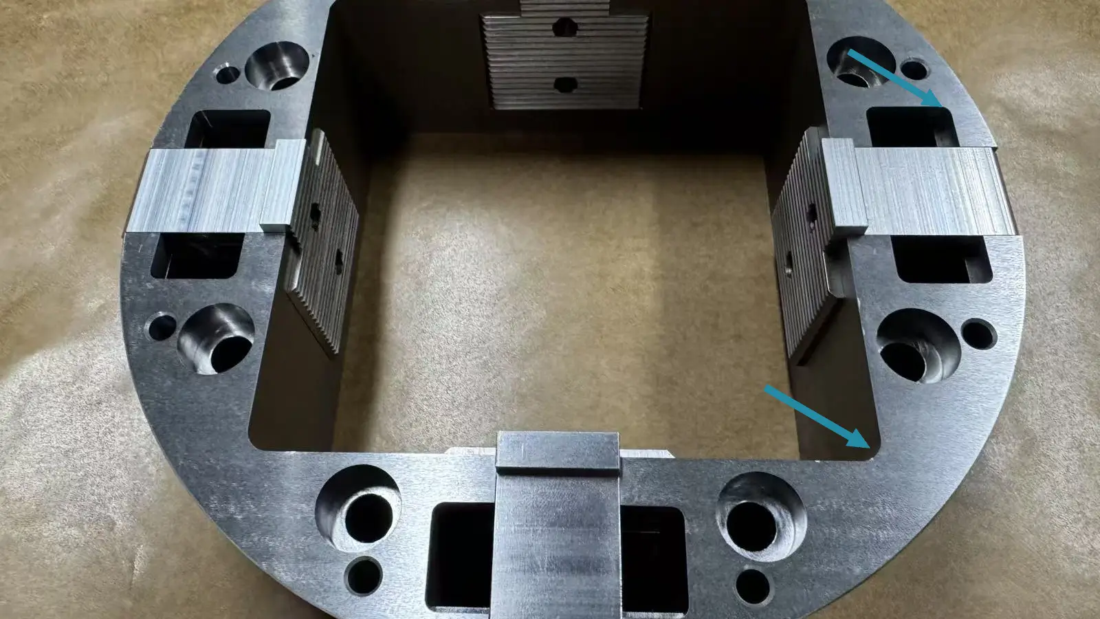
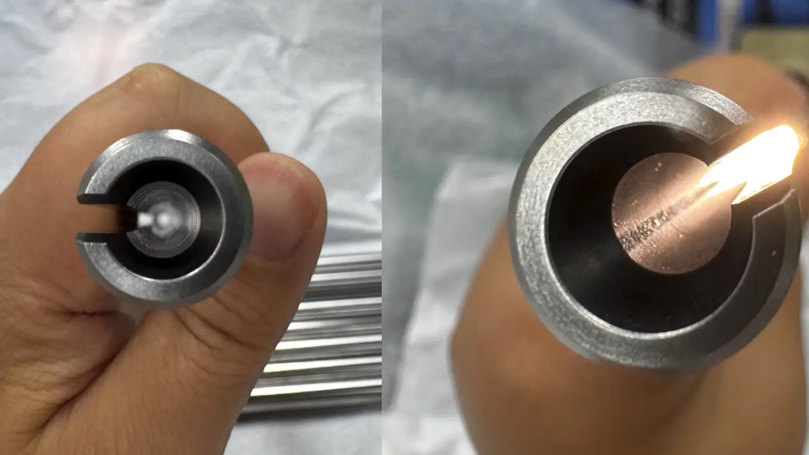
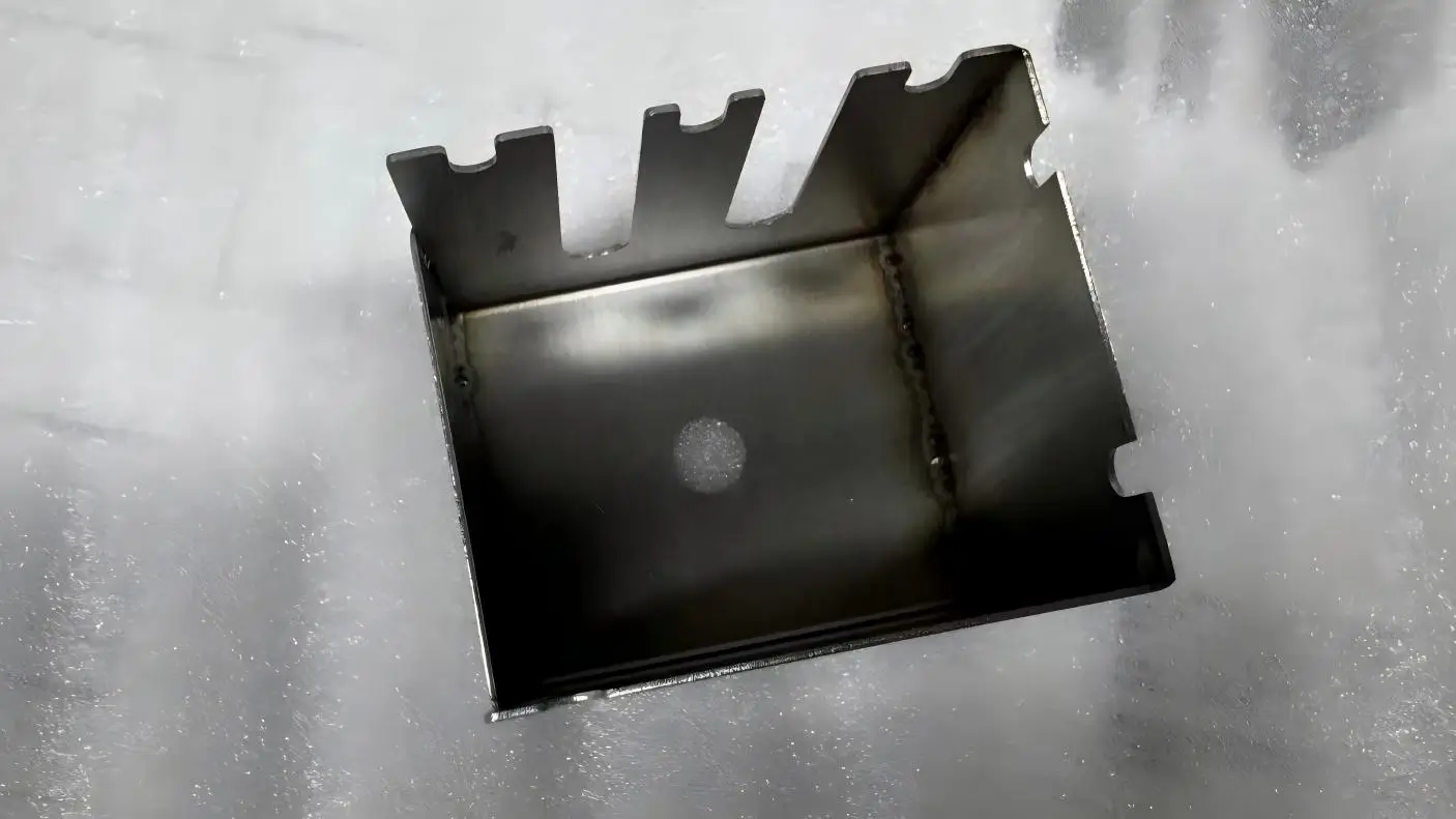
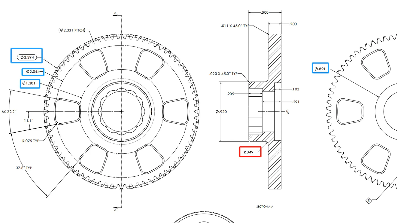
Radius is in chamfers (R corners), grooves, edges of round holes, and other geometric features. Compared to diameter, radius is more often used to measure local curved or rounded profiles.
We use Radius Gauge, Vernier Caliper, CMM (Coordinate Measuring Machine),Optical Comparator / Vision Measuring System, Contour Measuring Machine (Profilometer) to measure the radius.
A radius gauge is a simple, go/no-go tool made of a set of metal blades with pre-defined radii (e.g., R1 to R25).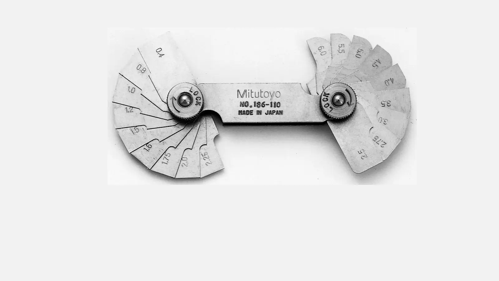
It’s used by matching the blade edge to the curve on the part to visually check if the radius is correct.
It is fast and inexpensive, but only gives a rough comparison, not suitable for high-precision needs.
Use the caliper to the chord length and height of height of an arc, then follow the below geometric formula to calculate the radius.
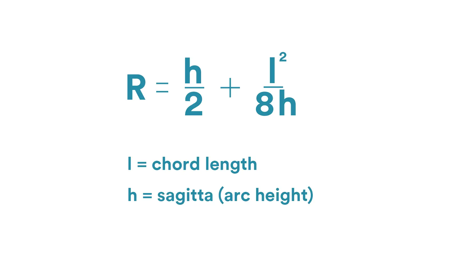
The accuracy depends on manual readings and calculation, not suitable for complex contours or very small radii.
CMM can provide high-precision radius values along with full geometric data like roundness, center position, and deviation.
It’s ideal for parts with tight tolerance or when inspection reports are needed.
Optical Comparator / Vision Measuring System can project or capture a magnified image of the part’s edge.
Inspect or digitally measure the radius directly from the screen.
For small, transparent, or delicate parts where contact measurement isn’t ideal, Optical Comparator is a good choice. The accuracy is high, and many systems support automatic edge detection for fast results.
A contour measuring machine traces the surface profile of the part with a stylus and generates a precise curve on screen.
The software then calculates the radius, curvature, and transition zones in great detail.
It is the most accurate method for analyzing complex or blended curves, and is widely used in mold, optics, and die industries. The contour measureing machine is very expensive.
Below is the table about how to choose a Radius measurement method.
| If you want to… | Recommended Method |
| Quickly verify if the radius is present | Radius Gauge |
| Roughly estimate the radius value | Vernier Caliper + Geometric Formula |
| Precisely measure radius size and tolerance | CMM or Optical Comparator |
| Analyze high-precision continuous contour | Profilometer |
An example is given below for a part with a corner radius specified as R2.50 ± 0.05 mm.
| Approach | Tool | Accuracy Requirement | Recommendation Level |
| Quick Check | Radius Gauge (R2.5) | Rough estimate |  |
| Precision Check | CMM (Coordinate Measuring Machine) | Within ±0.05 mm | |
| Optical Inspection | Optical Comparator / Vision System | Small parts / clear edges | |
| Complete Surface Analysis | Profilometer (Contour Measuring Machine) | Requires full curvature or transition data | |
In fact, radius and diameter are very similar. They are both core geometric parameters describing circular or spherical features and are both defined around the center of the circle or sphere. Their values are directly related, and both require specific symbols in engineering annotations to clarify the feature type.
They are both used to precisely control the dimensional accuracy of parts and are fundamental parameters in CAD modeling, CNC programming, and processing inspection.
Radius (R): refers to the fixed distance from the center of the circle to any point on the arc, it is a one-way measurement that determines the degree of curvature of the arc, the smaller the value, the more curved the arc is, e.g., the rounded corners of a cell phone casing, R2mm, enhances the comfort of the grip.
Diameter (⌀): It refers to the length of a bi-directional line segment passing through the center of a circle, with a value of twice the radius (⌀ = 2R), and is often used to describe the overall span of a circular or spherical feature, e.g., ⌀50mm for a bearing hole, which specifies the overall size of the hole .
Radius: use the letter “R” as a prefix, for example, R10mm represents a circular arc with a radius of 10mm, and the spherical radius is labeled as SR, like SR20mm means that the spherical radius is 20mm.
Diameter: the symbol “⌀” will be added before the numerical value when labeling. “, like ⌀20mm, S⌀40mm (for sphere).
Radius: mainly used to control the curvature of circular transition, such as the R3mm fillet of the shaft shoulder of mechanical parts, which can reduce the stress concentration and improve the assembly precision; also used to describe the spherical parts, such as the SR32mm radius of the bearing ball.
Diameter: Focuses on determining the overall size of features such as round holes and shaft diameters, influencing the selection of tool diameters. For instance, fabricating a ⌀10mm bolt hole necessitates a drill bit of matching diameter.
Learn more about diameter: Diameter Symbol in Engineering Drawing
Apart from diameter, there are several other concepts that are easily confused with radius, as detailed below:
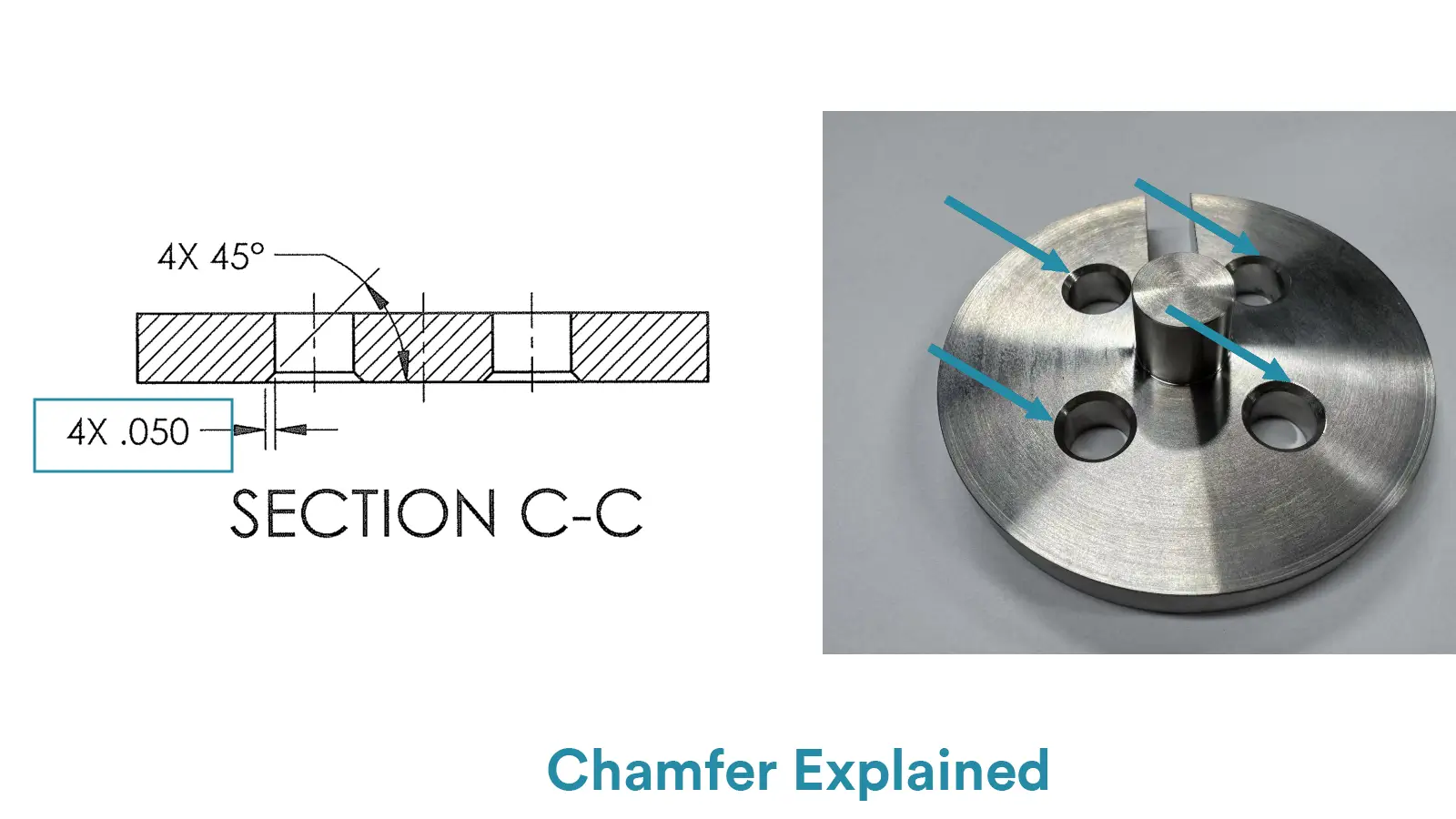
Definition: A chamfer is a linear beveled transition feature formed by the intersection of two planes, typically denoted by “C + numerical value”. Non-45° chamfers require both angle and length specifications (e.g., 2×60°). Its core purpose is to deburr edges, facilitate assembly, or reduce stress concentration through beveled edges.
R is a rounded curve, while a chamfer is a straight, angled surface.
In CNC machining, chamfers often aren’t explicitly called out on drawings because they typically include notes like “BREAK ALL SHARP EDGES AND REMOVE BURRS.” This usually indicates the customer wants small chamfers—such as C0.1, C0.2, or C0.5. Sometimes, the drawing may also include a note like “Unmarked edges to be
In practice, chamfers are wrongly called “R corners,” especially small ones that resemble small-radius arcs (e.g., R1mm). Since both can be milled or ground and serve similar functions like edge treatment, the “R” and “C” symbols are often mixed up, causing mislabeling or incorrect machining in design and production.
Definition: The radius of curvature is a parameter describing the degree of curvature at a point on non-circular curves (e.g., ellipses, parabolas, gear involutes).
It is the reciprocal of the tangent direction change rate at that point, equivalent to the radius of the best-fitting circle approximating the curve locally.
Reason for confusion: The term “radius of curvature” includes “radius,” which can easily be confused with the fixed radius (R) of circular arcs. In engineering notation, it is frequently abbreviated as “R” (e.g., R500mm), mirroring the traditional symbol for radius.
Critically, the former represents a local variable along a curve, whereas the latter denotes a fixed distance from a circle’s center. Despite their fundamental conceptual differences, design conventions often overlook distinctions in naming and notation, leading to misinterpretations.
Curvature radius” is more of a design or modeling term and is rarely used in CNC machining drawings or programming.

5-Axis CNC machining is a manufacturing process that uses computer numerical control systems to operate 5-axis CNC machines capable of moving a cutting tool or a workpiece along five distinct axes simultaneously.

China is the best country for CNC machining service considering cost, precision, logistic and other factors. Statistical data suggests that China emerges as the premier destination for CNC machining.

Selecting the right prototype manufacturing supplier in China is a critical decision that can significantly impact the success of your product development project.

Machining tolerances stand for the precision of manufacturing processes and products. The lower the values of machining tolerances are, the higher the accuracy level would be.