Home » Blog » Dimensional Origin in GD&T

Dimensional Origin in GD&T

By Lucas Lo | Updated: July 14, 2025

Table of Contents

    Dimensional Origin is the basic reference starting point for dimensioning in mechanical manufacturing and engineering design, which runs through the whole process from design to processing and testing of parts. Understanding the definition, role and design principles of the origin of dimensions is an important prerequisite for accurately interpreting engineering drawings and ensuring the quality of parts.

    In this article, we will systematically sort out the core knowledge of Dimension Origin to provide clear guidelines for related practitioners.

    1. What is Dimension Origin?

    In the following, we will start from the definition, explain the core meaning of Dimension Origin as the starting point of part dimensioning datum, and then discuss its connection with the coordinate system, and clarify the difference between it and Measurement Datum, Process Datum, and Datum , so as to help the readers to understand this concept comprehensively.

    1.1. Definition of Dimension Origin 

    Dimension Origin is the baseline starting point for part dimensioning, i.e., where to start measuring or calculating the dimensions of a feature, and also the frame of reference for measuring the geometric dimensions of each feature of a part. It is widely used in machinery manufacturing, mold design and other fields, such as precision gears, engine blocks, electronic component housings and other parts in the processing and inspection.

    Dimensional Origin in GD&T

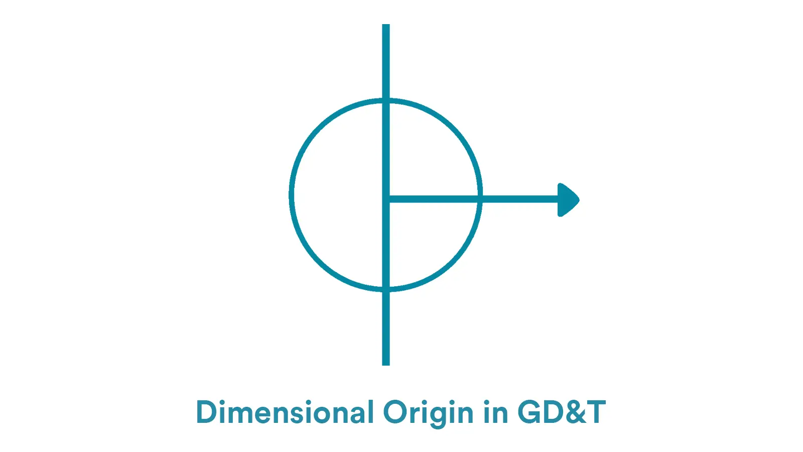
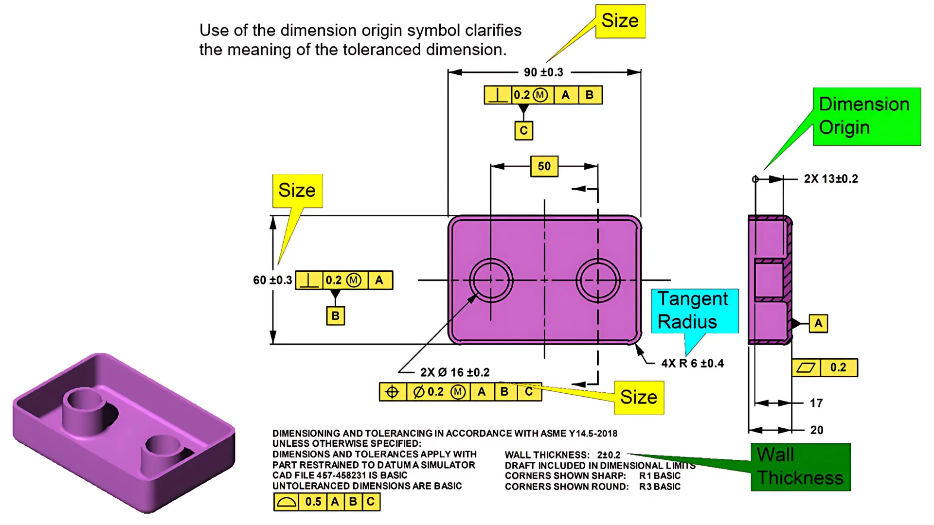
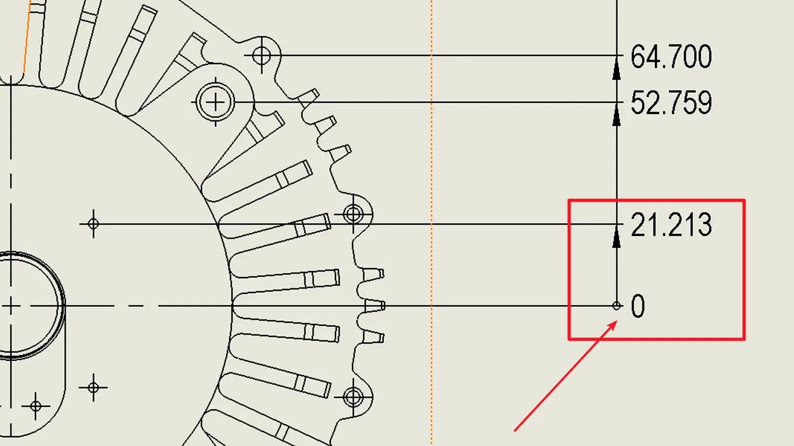
    In engineering drawings, Dimension Origin is usually identified by a specific symbol, generally a circle or square with a cross, running through the key datum or axis of the part, providing a clear starting point reference for dimensioning. As a key communication tool between design and manufacturing, it clarifies the datum for dimensional measurement, ensures consistent understanding of part dimensions during machining and inspection, and safeguards part consistency and compliance.

    1.2. Relationship with the Coordinate System

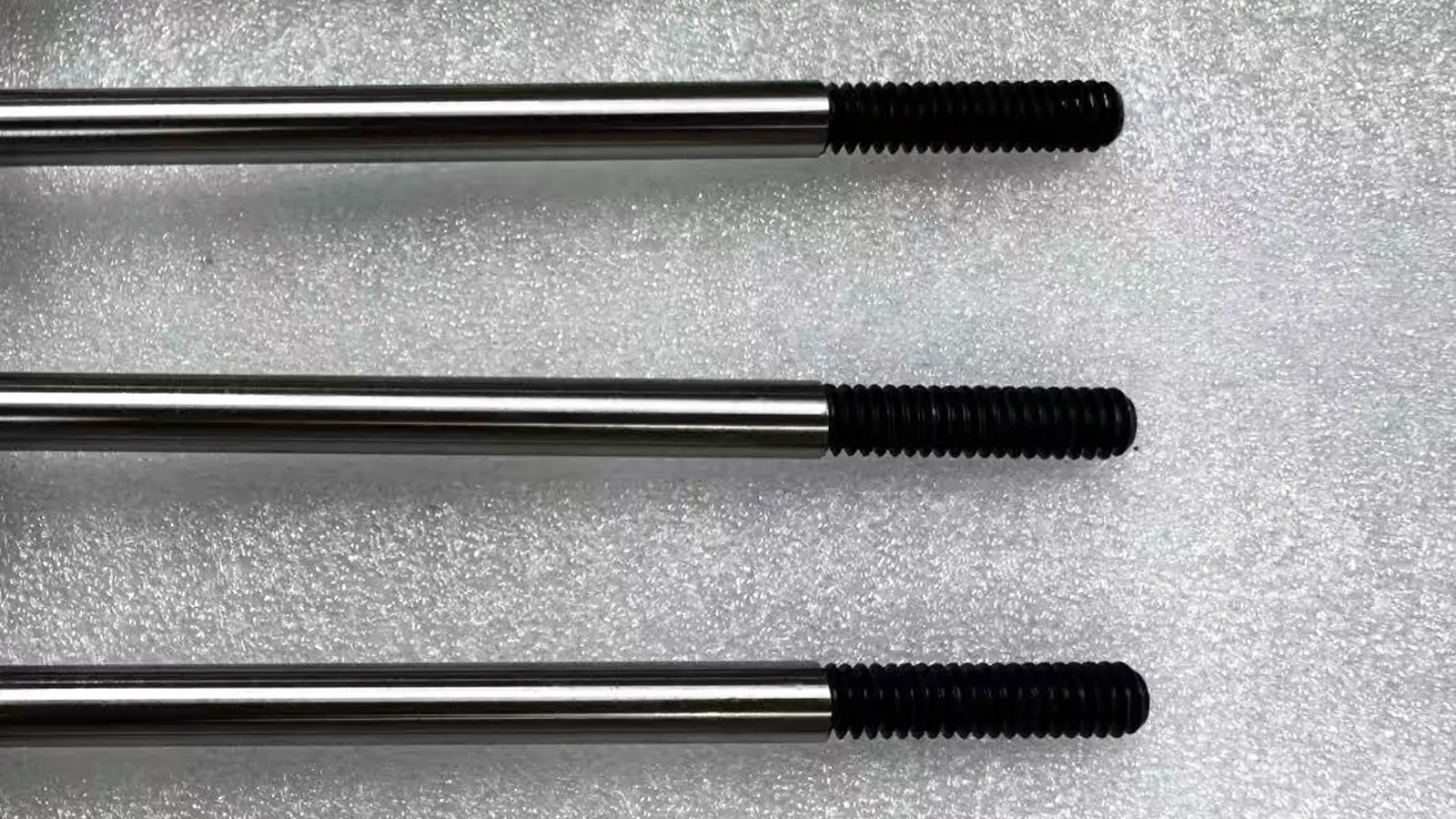
    Dimension Origin is the core datum for the establishment of the coordinate system, and the X, Y, and Z axes of the part’s coordinate system are usually extended with Dimension Origin as the starting point. For example, in the processing of shaft parts, Dimension Origin is always set at the center of the end face of the shaft, which is used as a benchmark to determine the size and position of each segment of the shaft diameter, and its position directly determines the positioning of the coordinate system, which in turn affects the dimensional accuracy of each feature of the part.

    The shaft parts shown in the figure take the center of the end face as Dimension Origin and establish X, Y, and Z coordinate systems to guide the dimensioning and machining positioning of each segment of the shaft diameter.

    1.3. Difference with Other Concepts

    Dimension Origin VS Measurement Datum:

    Dimension Origin is the original starting point for dimensioning, and it is the datum determined at the drawing design stage; Measurement Datum is the reference point chosen for actual inspection, which may be the same as Dimension Origin, or it may be chosen according to the needs of inspection, but Dimension Origin is the fundamental basis.

    It may be consistent with Dimension Origin, or other points may be selected according to inspection needs, but Dimension Origin should be the fundamental basis.

    Dimension Origin vs. Process Datum:

    Dimension Origin focuses on the datum for dimensioning, while the process datum is the datum used for positioning and clamping in the machining process. Although they are related, they are used for different purposes, and the selection of the process datum often needs to refer to the Dimension Origin.

    1.4. Difference from Datum

    Parameter

    Dimension Origin

    Datum (Geometric Datum)

    Function

    Solely serves as the starting point for dimensioning

    Controls form, orientation, and tolerance references

    Representation

    Implicitly indicated within the dimension chain

    Explicitly labeled with datum symbols (e.g., A, B, C)

    Control Scope

    Reference position for dimensional values

    Basis for geometric form constraints

    Note:

    Datum, as defined in the GD&T framework, is frequently employed to establish a spatial positioning system for parts.

    Dimension Origin is more oriented towards general dimensioning: it indicates the point/plane from which a specific dimension should be measured.

    Both can appear in the same drawing, but they are used for different purposes: one is used to define geometric constraints and the other is used only for dimensioning.

    2. What is the Role of a Dimension Origin?

    This section focuses on the specific functions of Dimension Origin in the actual production process, and explains its key role in guaranteeing the accuracy and consistency of parts machining from three aspects: the positioning datum for parts machining, the datum for dimensioning, and the basis for quality inspection.

    2.1. Part Machining Positioning Reference

    Dimension Origin provides a clear basis for the positioning of the part in the machine tool and is the key to determining where the part will be machined. For example, when machining box parts, using Dimension Origin as a reference to adjust the position of the part on the table ensures that the dimensions of the machined surfaces are in accordance with the drawing.

    2.2. Dimension marking reference

    It is the starting point of all dimension marking, and the dimensions of each feature on the part are marked with reference to Dimension Origin, which makes the information on the drawing clear and uniform, and facilitates the processor’s understanding and execution.

    2.3. Quality Inspection Basis

    During part inspection, the inspector uses Dimension Origin as the reference to measure the actual dimensions of each feature to determine whether they are within tolerance, which is an important reference for assessing the quality of the part.

    how to measure a dimension with the dimension origin symbol

    3. What are the Key Design Points of a Dimension Origin?

    This section will focus on the principles to be followed when designing for Dimension Origin, including the selection of the datum plane, the coordination with the assembly datum, whether it is easy to mark and measure, and how to ensure that the dimensioning is clear and intuitive. The details are as follows:

    Firstly, Dimension Origin should be used on important datum surfaces of the part, such as the bottom surface, end surfaces, or center of symmetry surfaces, which usually have high accuracy and stability.

    Secondly, For parts with assembly requirements, Dimension Origin should be aligned with the assembly datum as much as possible to minimize assembly errors, e.g., the Dimension Origin of a gear is always set at the center of the bore that mates with the shaft.

    Thirdly, The Dimension Origin should be easy to dimension and measure, avoiding the selection of locations that are difficult to access or measure, and ensuring the convenience of the machining and inspection process.

    Finally, Dimensioning should be clear and intuitive, avoiding closed dimensional chains, and making it easy for processors to understand and control dimensional accuracy.

    4. What are the Common Types of Dimension Origin?

    According to the level of “starting position”, Dimension Origin can be divided into four types, as follows:

    4.1. Edge starting point

    Commonly used for simple parts, such as rectangular blocks.

    The starting point is clear, but is prone to cumulative errors.

    4.2. Hole Center Starting Point

    Commonly used for rotationally symmetric features such as locating holes and shaft parts.

    It meets the dimensioning requirements of rotationally symmetric features and facilitates the control of radial dimensions.

    4.3. Symmetric Center Starting Point

    Commonly used for intermediate symmetric parts.

    It can reduce the length of dimensional chain and the cumulative error.

    4.4. Coordinate origin starting point

    In CNC machining, this corresponds to the zero point of the workpiece coordinates.

    It is typically designated as the origin of one of the work coordinate systems G54-G59.

    Dimensional Origin Callout

    5. What are the Common Problems and Solutions for Setting a Dimension Origin?

    This section will analyze the problems that can occur during the setup of Dimension Origin and give solutions for each problem to avoid potential risks.

    5.1. Inappropriate Selection of Datum

    Selecting datums that are not related to the functional requirements will lead to the failure of parts with qualified dimensions, such as using easily deformed surfaces as datums for load-bearing parts.

    Therefore, it is necessary to combine the functional requirements with FMEA analysis, and prioritize the selection of features related to the main function and assembly relationship as the datum.

    5.2. Multi-Feature Origin Conflict

    The logic of multi-feature origin in complex parts is confusing, which leads to the calculation error of dimension chain and increases the processing difficulty.

    Therefore, it is necessary to establish a unified datum system, using the main datum combined with local offset mode, so that the local origin and the datum origin to form a correlation.

    5.3. Origin Offset

    Thermal deformation of the machine tool, tool wear during machining, or equipment errors during inspection lead to origin offset, which affects accuracy.

    Therefore, preheat and calibrate the machine before machining, and compensate the tool regularly; ensure the accuracy of the equipment during inspection, and verify the measurement several times.

    6. Conclusion

    Dimensional origin is the starting point for dimensioning in mechanical design and manufacturing, and is closely related to the coordinate system, which is not only different from the process reference, measurement reference and geometric datum in GD&T, but also runs through the whole process of the parts, providing a unified reference for machining and positioning, dimensioning and quality inspection.

    Its design must follow the principle of functional priority to avoid issues such as improper datums and multi-origin conflicts; reasonable application is key to ensuring part accuracy and production efficiency.

    Lucas

    Lucas is a technical writer at ECOREPRAP. He has eight years of CNC programming and operating experience, including five-axis programming. He also spent three years in CNC engineering, quoting, design, and project management. Lucas holds an associate degree in mold design and has self-taught knowledge in materials science. He’s a lifelong learner who loves sharing his expertise.

    Learn More about Lucas.

    Let's get your projects started, together!

    Get custom parts machined in high quality, delivery on time.