CNC prototyping is often the first real-world validation of a product design. At this stage, the quality of your CAD files directly affects machining accuracy, lead time, cost, and the number of revision cycles required before approval.
In practice, many CNC machining issues do not originate from machine limitations, but from CAD files that were not properly prepared for CNC manufacturing.
Optimizing CAD files for CNC prototyping means adjusting geometry, tolerances, and file formats so designs can be machined accurately, efficiently, and with minimal rework.
When CAD files are optimized correctly, CNC prototypes are produced faster, with fewer questions from machine shops and significantly less risk of rework.
In CNC prototyping, time and iteration cost matter more than cosmetic perfection.
A CAD model that looks correct on screen can still cause machining issues such as broken tools, excessive setup time, or dimensional inaccuracies.
Unoptimized CAD files are one of the primary causes of CNC machining errors, longer lead times, and higher prototype costs in prototyping projects.
Industry experience shows that early CAD optimization can reduce rework requests by 30–50% during prototype machining.
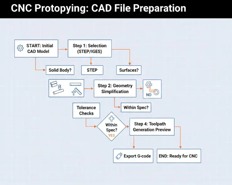
Use a CNC-friendly neutral format such as STEP, IGES, or Parasolid, verify units, and remove unnecessary features so the model is clean, watertight, and contains only machinable geometry.
Apply design-for-manufacturability rules like using standard hole sizes, avoiding overly deep or thin features, adding adequate fillet radii, and clearly defining tolerances to reduce setup time and machining cost.
For CNC prototyping, STEP files are the preferred CAD file format because they preserve solid geometry and are reliably interpreted by most CAM systems. STEP (.stp or .step) files minimize the risk of missing faces, surface gaps, or translation errors during toolpath generation.
IGES files are still used in some workflows, but they often store surface data instead of solid bodies. This can lead to ambiguity during CAM programming and increase the likelihood of machining errors.
Best practices include exporting only solid bodies, removing construction sketches, and avoiding unnecessary assembly data unless explicitly required by the machine shop.
Simplifying CAD geometry for CNC machining can reduce toolpath complexity and shorten machining time by approximately 20–40% in typical prototype runs.
Complex geometry does not automatically improve prototype performance and often increases machining risk.
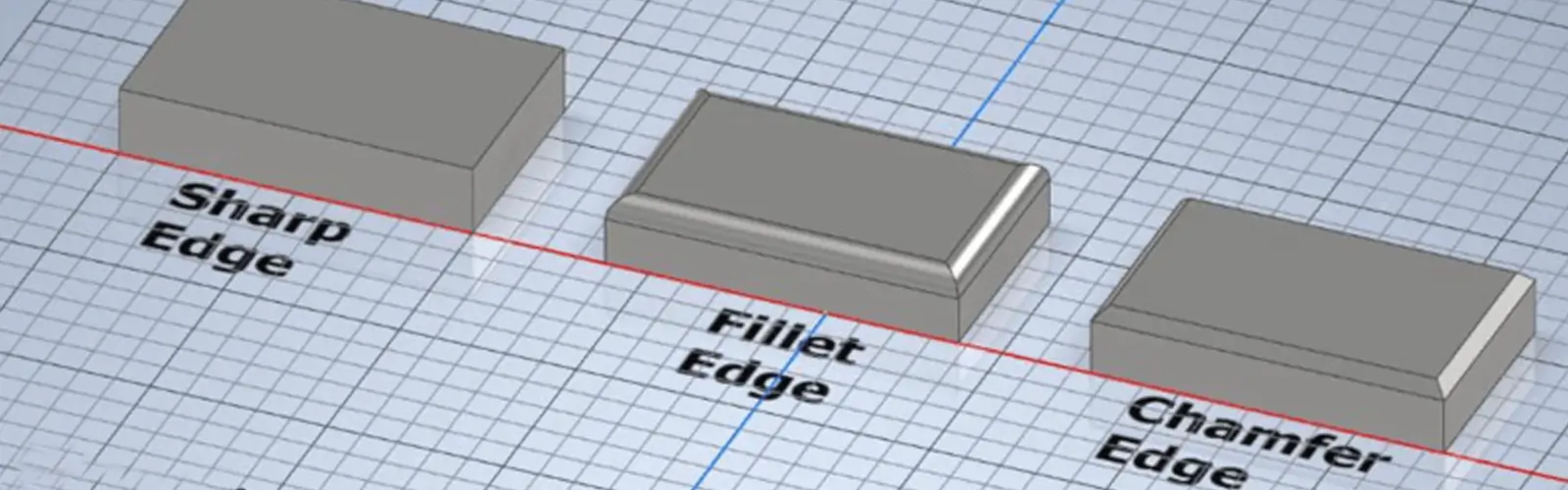
Remove decorative fillets, cosmetic chamfers, and surface details that do not affect form, fit, or function. Simplified geometry enables more efficient toolpaths, fewer tool changes, and more stable cutting conditions.
From a machinist’s perspective, if a feature does not contribute to functional testing, it should not exist in a CNC prototype.
For most CNC prototypes, a general tolerance of ±0.1 mm (±0.004 inch) provides sufficient accuracy without increasing machining cost or risk.
Applying tighter tolerances than necessary increases machining time and tool wear without improving prototype validation.
Tighter tolerances should be reserved for critical-to-function features such as bearing seats, mating interfaces, or alignment surfaces.
Using general tolerances and clearly identifying critical dimensions is one of the most effective ways to reduce CNC machining tolerance issues.
Wall thickness and hole geometry have a direct impact on tool stability and part integrity. Thin walls and deep holes are common causes of vibration, tool deflection, and surface defects in CNC prototyping.
As a general guideline, minimum wall thickness should be approximately 1.0 mm for aluminum, 1.5 mm for steel, and 1.2 mm for engineering plastics.
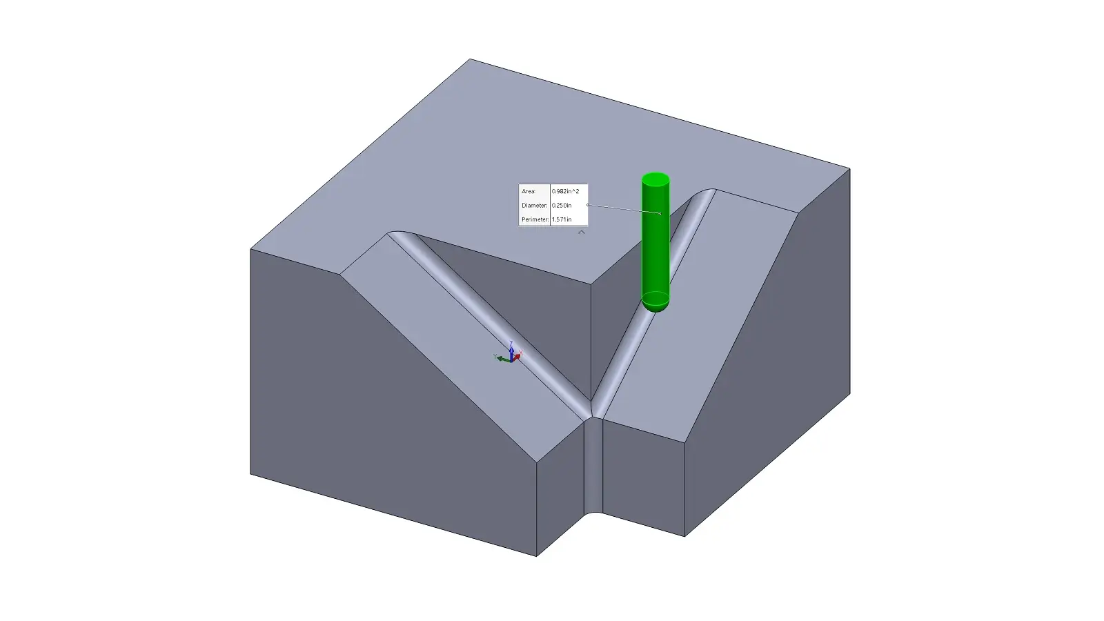
To maintain tool stability in CNC prototyping, hole depth-to-diameter ratios should ideally remain below 5:1. Adding internal fillets of 0.5 mm or larger improves machinability and tool access.
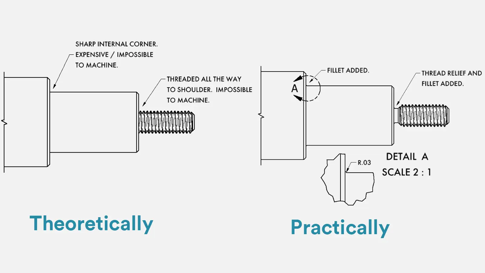
Certain CAD features may be geometrically valid but impractical or impossible to machine using CNC processes.
These include zero-radius internal corners, extremely thin ribs, and intersecting or open surfaces.
Proper CAD file preparation reduces CNC machining errors by eliminating non-manufacturable features and ensuring geometry can be accessed using standard cutting tools.
Removing these features early can reduce CNC machining errors by more than 25% in typical prototype runs.
Correct file export is critical to successful CNC prototyping. Units, coordinate origin, and model orientation must be clearly defined before sending files to a machine shop.
STEP AP214 or AP242 formats are commonly recommended. Mesh exports should be avoided unless specifically requested, as they reduce geometric precision and complicate CAM programming.
After export, opening the file in CAM or neutral viewer software is a simple but effective way to catch potential issues before machining begins.
Professional CNC prototyping workflows follow design-for-manufacturing (DFM) principles applied across aerospace, automotive, and industrial sectors. ISO 9001-certified machine shops increasingly emphasize early CAD optimization to reduce lead times and machining risk.
Between 2024 and 2025, CNC prototype lead times typically range from 3 to 10 business days, depending on part complexity. Designs that follow CNC machining design guidelines consistently achieve faster turnaround and fewer engineering revisions.
Optimizing CAD files for CNC prototyping involves selecting a solid-based file format such as STEP, simplifying geometry, applying realistic tolerances, validating machinable features, and exporting files in a way that CAM software can interpret accurately.
For CNC prototyping, STEP files are generally preferred over IGES because they preserve solid geometry more reliably and are interpreted more accurately by most CAM systems.
For most CNC prototypes, a general tolerance of ±0.1 mm (±0.004 inch) provides sufficient accuracy without significantly increasing machining time, cost, or risk.
Proper CAD file preparation reduces CNC machining errors by eliminating non-manufacturable features, applying appropriate tolerances, and ensuring geometry can be accessed and cut using standard CNC tools.
Optimizing CAD files for CNC prototyping is a practical process that reduces machining errors, shortens lead times, and lowers prototype costs.
By selecting the correct file format, simplifying geometry, applying realistic tolerances, validating machinable features, and exporting files correctly, designers can significantly improve CNC prototyping outcomes.
In CNC prototyping, success depends not on design complexity, but on how effectively a design translates into machinable reality.

5-Axis CNC machining is a manufacturing process that uses computer numerical control systems to operate 5-axis CNC machines capable of moving a cutting tool or a workpiece along five distinct axes simultaneously.

China is the best country for CNC machining service considering cost, precision, logistic and other factors. Statistical data suggests that China emerges as the premier destination for CNC machining.

Selecting the right prototype manufacturing supplier in China is a critical decision that can significantly impact the success of your product development project.

Machining tolerances stand for the precision of manufacturing processes and products. The lower the values of machining tolerances are, the higher the accuracy level would be.