There are three material modifiers in Geometric Dimensioning and Tolerancing(GD&T), including Regardless of Feature Size, Least Material Condition, and Maximum Material Condition.
Among the three callouts, Maximum Material Condition plays a crucial role in ensuring proper fit between two mating parts and promoting the interchangeability of components.
GD&T Maximum Material Condition(MMC) is a feature of size symbol which refers to the dimensional condition where the particular feature contains the maximum amount of material within its indicated tolerance.
For internal features and external features, the relationship between the amount of machined material and the feature’s dimension is totally contrast. For internal features, more material contained means smaller dimension; while for external features, more material contained means exactly larger dimension.
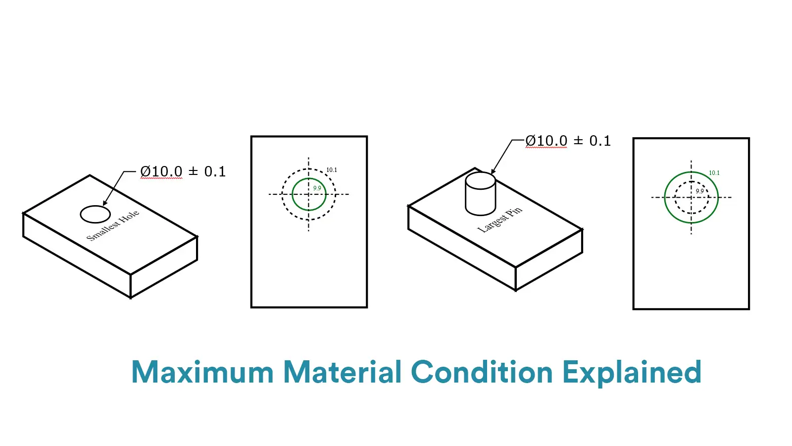
Therefore, Maximum Material Condition can be simply explained as follows:
For an internal feature like a hole, MMC=Smallest size of the hole
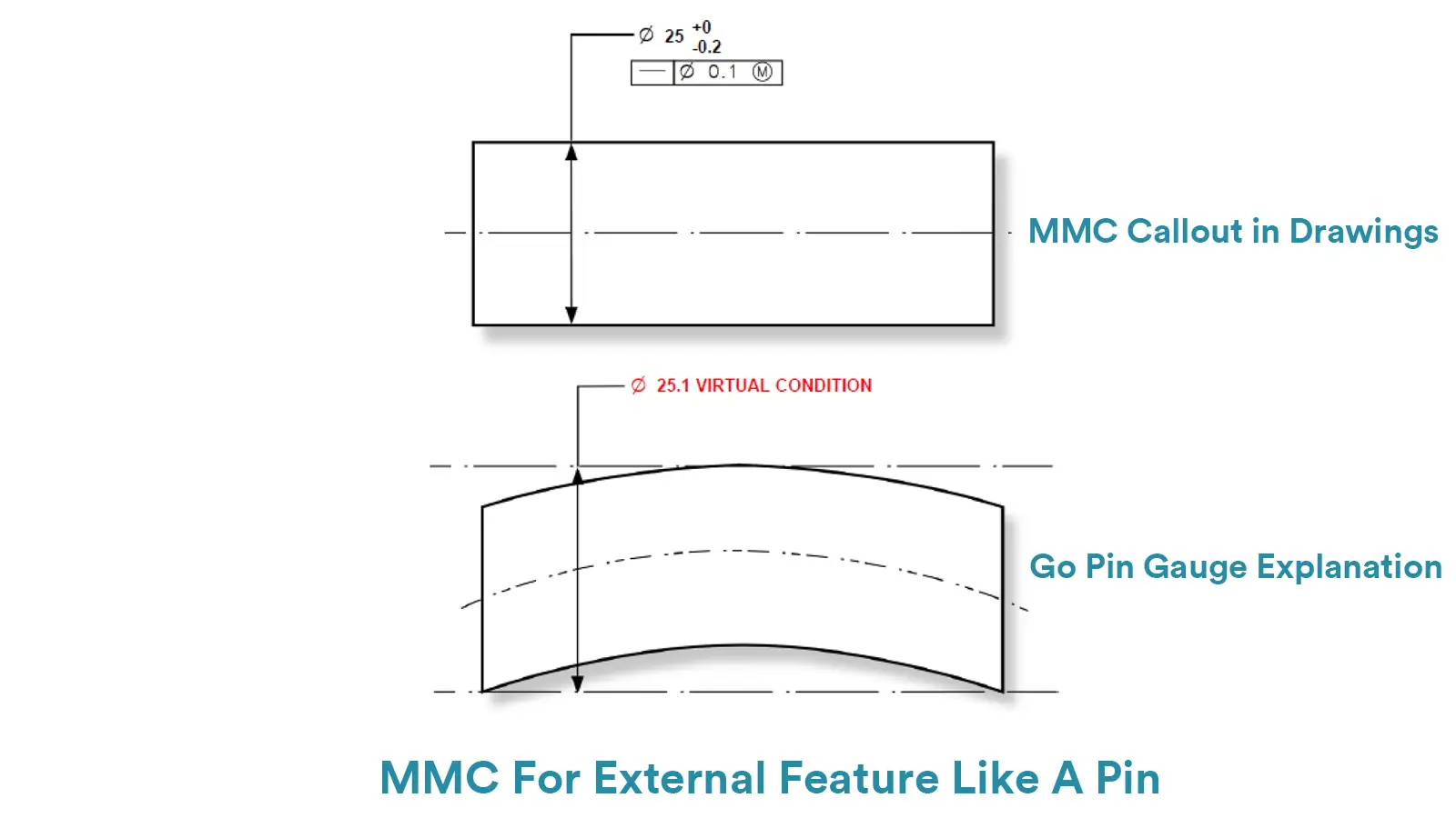
For an externa feature like a pin, MMC=Largest size of the pin
In conclusion, maximum material condition is also one end of a part’s dimensional range. It is contrast to least material condition, which refers to the condition where least amount of material is contained for a feature.
In a feature control frame, if required, it would be indicated just after the tolerance value as M, which is the maximum material condition symbol.
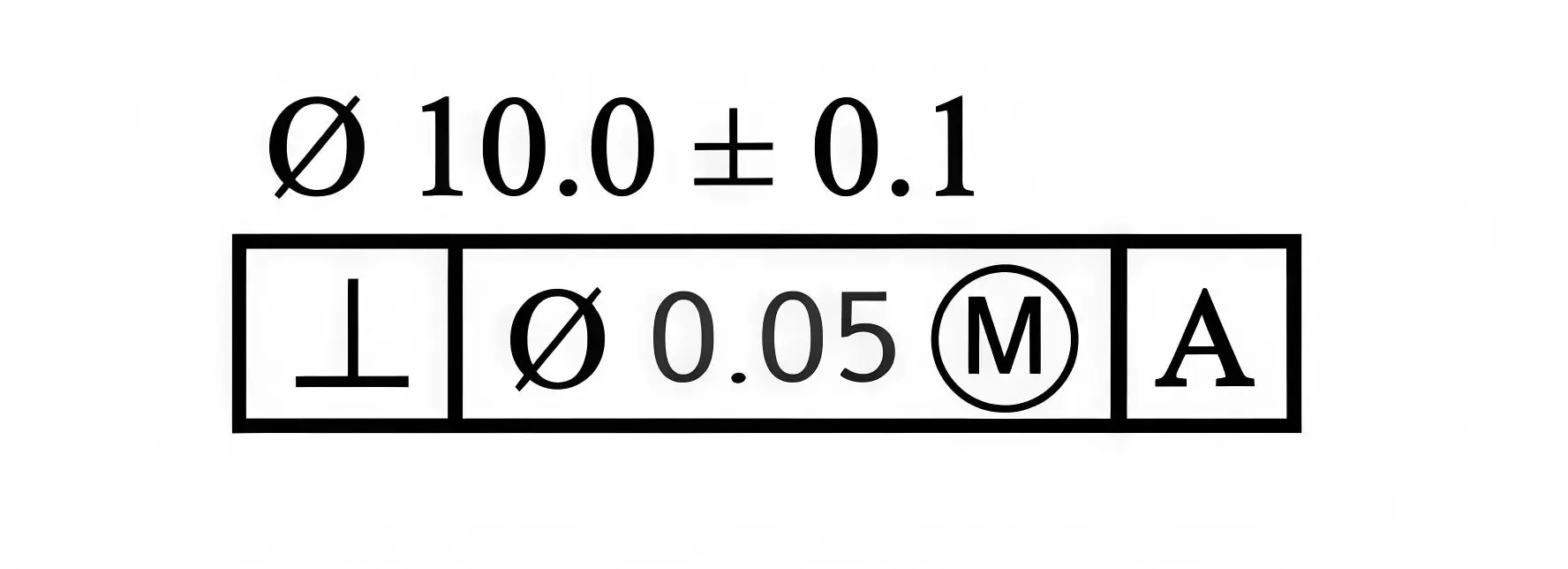
MMC is always called out when two parts should be ensured never interfere, or the amount of interference between the parts should be limited when they are at their worst tolerances.
In fact, compared with Least Material Condition, Maximum Material Condition is used much more frequently in Geometric Dimensioning and Tolerancing. The essential functions of MMC are as followed.
One of the most critical functions of Maximum Material Condition is to ensure that two mating parts can be assembled properly even when they are at their worst material condition(largest or smallest permissible sizes).
The most common applicated situation of MMC is when two parts should be assembled always with clearance. For instance, if the MMC of a shaft is made sure to always be smaller than the MMC of a hole, there will always be clearance between the two parts.
Another critical function of MMC is to provide bonus tolerance for indicated geometric tolerance. MMC defines that when the actual dimension of the feature deviates from its MMC towards LMC, the allowable geometric tolerance would increase as much as the deviation.
For a shaft, the Bonus Tolerance=MMC-the Actual Dimension
For a hole, the Bonus Tolerance=the Actual Dimension-MMC
LMC with geometric tolerance cannot be measured by a No-Go Gauge at once. They should be measured respectively, using No-Go Gauges to measure LMC and CMCs or other means to measure geometric tolerance.
However, MMC can be measured with geometric tolerance in the meantime by a specific functional gauge, which can effectively elevate the measurement efficiency.
Since MMC makes beneficial effect on improve parts’ fitting and extend geometric tolerance, which can respectively elevate interchangeability and widen acceptable manufacturing accuracy, the cost in production of parts with MMC can be effectively reduced.
Just like No-Go Gauges that used for Least Material Condition, Go-Gauges are also a kind of specific functional gauges, but they are used especially to control the Maximum Material Condition of features.
When you want to ensure a proper fit, especially a clearance fit, by limiting the feature’s dimension, you can specify the MMC callout of the feature and control it with a Go-Gauge(meaning the part must always go through it).
For instant, if you want to make sure that a pin would always have a clearance fit with a hole that is at its MMC, you can design a Go-Gauge that simulates the maximum material condition of the pin. The Go-Gauge would be a block with a hole whose diameter is just a little larger than the pin’s MMC(the pin’s maximum diameter).
And then you should insert the pin into the hole to check if the part is in spec. If the pin does fit into the hole, to say go into the hole, then it has been checked that the pin is small enough to have a clearance fit with the feature.
A Go-Gauge for a hole would be a pin gauge whose diameter is equal to the hole’s minimum diameter(Gauge’s Ø=Hole’s Min Ø).
A Go-Gauge for a pin would be a hole gauge whose diameter is equal to the pin’s maximum diameter(Gauge’s Ø=Pin Max Ø).
Note that a pin gauge may be made slightly smaller than the hole’s MMC and a hole gauge may be made slightly larger than the pin’s MMC considering any inherent manufacturing error of the gauge itself.
More importantly, such gauges are used only for MMC without GD&T symbols.
Compared with Least Material Condition, one of the most crucial benefits of using Maximum Material Condition on a feature is that MMC can be measured with GD&T Symbols at the same time by a specific Go-Gauge.
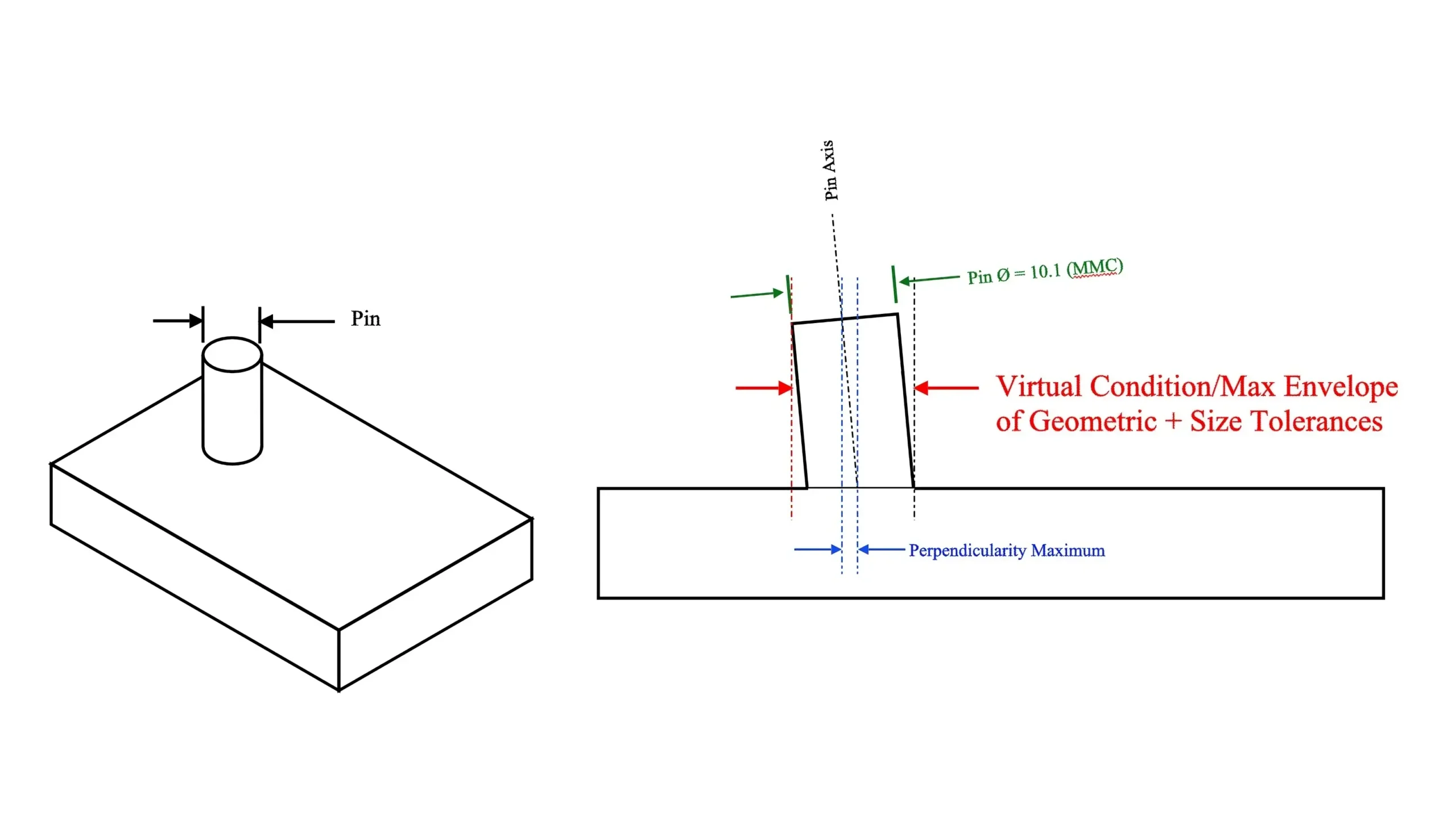
The reason is that when geometric tolerance and maximum material control are used together, they form the true maximum envelope or virtual condition that the part can be in and still be up to the standard.
Virtual Condition is served as the boundary formed by the collective effects of the specific MMC of a feature and any applicable geometric tolerance. And specific functional Go-Gauges that simulate the virtual condition can be used to measure MMC and geometric tolerance in the meantime.
For example, if there is a pin with both MMC and perpendicular callouts, a hole gauge simulates the worst-case limits at a 90° angle can be used to measure the pin. It means that the diameter of the hole gauge is the plus of MMC and max perpendicular tolerance of the pin and the pin needs to be within both perpendicular enough and small enough to go through its mating hole smoothly.
For an internal feature like a hole, the Go Pin Gauge Ø=Min Hole Ø-GD&T Symbol Tolerance Value
For an external feature like a pin, the Go Hole Gauge Ø=Max Pin Ø+GD&T Symbol Tolerance Value
MMC, LMC and RFS are all material modifiers that have different functions in GD&T. There are particular distinctions among them.
Both Maximum Material Condition and Least Material Condition are material modifiers that can provide bonus tolerance to indicated geometric tolerance. But their main functions are different.
Maximum Material Condition and Least Material Condition are two contrast sides of material contained situation. MMC contains the maximum amount of material for a feature while LMC contains the least amount.
The essential function of MMC is to make sure the mating parts assembled properly and to elevate the parts’ interchangeability. But the main function of LMC is to ensure the least thickness of material and reduce cost on expensive material.
Besides that, there is still a critical difference between MMC and LMC. That is , MMC can be measured with GD&T tolerance at the same time by a specific functional gauge, while LMC with GD&T tolerance can only be measured respectively. It means that measurement on MMC with GD&T Symbols is much simpler and less cost-consuming than that of LMC.
Read our blog: What is Least Material Condition?
Regardless of Feature Size is much different from MMC and LMC. Unlike MMC and LMC in which the actual geometric tolerance would change as the actual dimension of the feature changes. RFS defines that the geometric tolerance is fixed and independent to the feature’s size, meaning that RFS does not provide bonus tolerance.
And in a feature control frame, both MMC and LMC would be shown as their own symbol, but RFS would not be indicated in engineering drawings because RFS is the default situation. It means that if there is not any material modifier after the tolerance value, the GD&T tolerance is under RFS.
Therefore, RFS is particular used for the features that have tight requirements on geometric tolerance or key functions regardless of size.
Maximum Material Condition is a feature of size symbol that plays a huge role in GD&T. It is important to know about MMC clearly. If you have any confusion about MMC, contact with us directly.
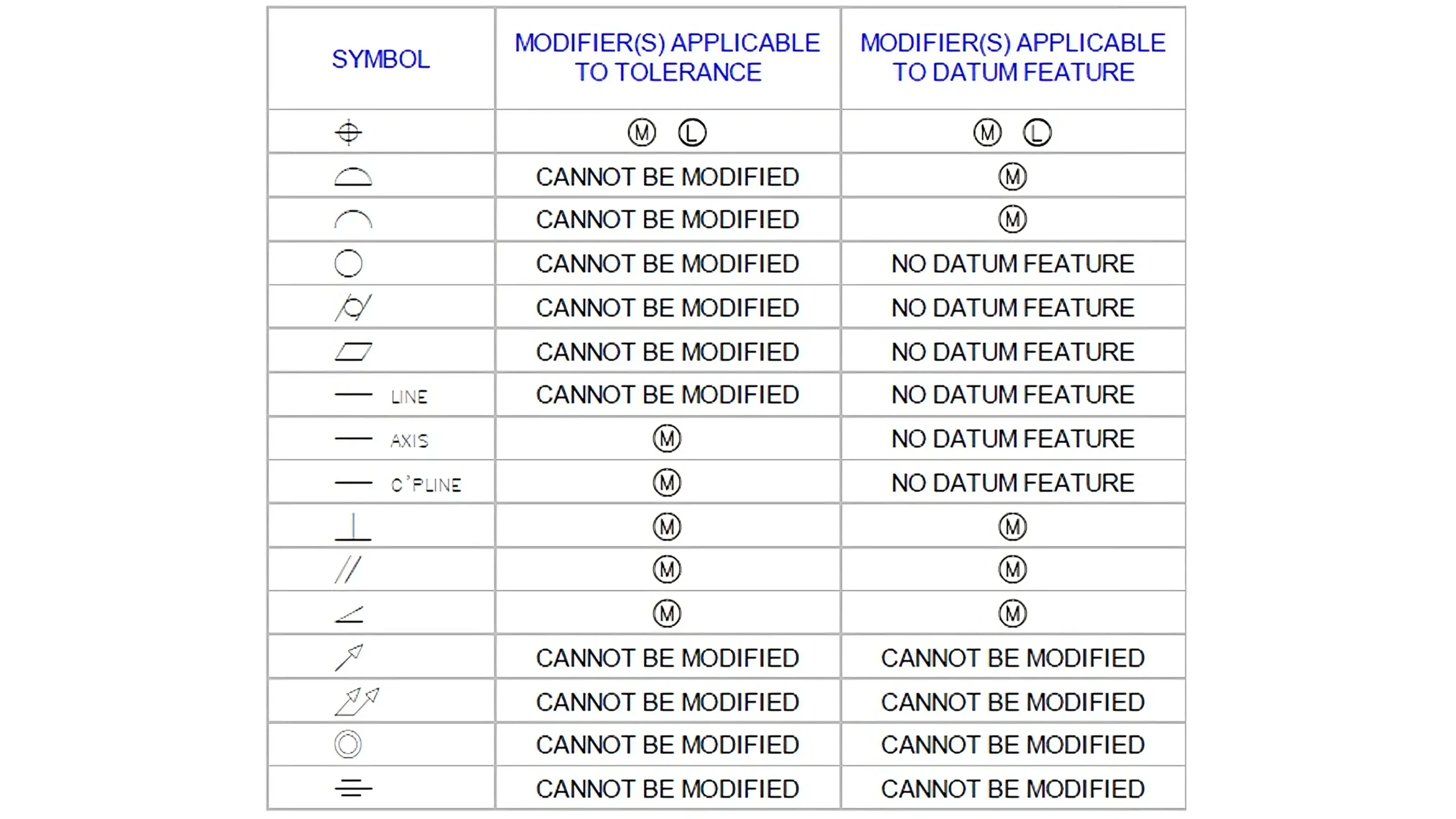
The answer is definitely no. MMC and LMC can only be applied to geometric features that is relative to size, especially GD&T Position and GD&T Perpendicularity. Below shows the features that are applicable for MMC and LMC.
Under the control of MMC or LMC, the actual geometric tolerance would change based on the actual dimension of the feature, which would add a bonus tolerance to the indicated tolerance value.
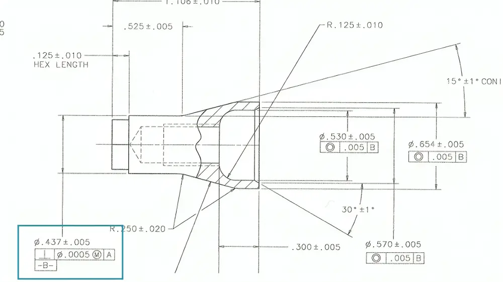
Not all the three material modifiers would be shown on engineering drawings. Both MMC and LMC have their specific symbols and would be indicated in the feature control frame just after the tolerance value.
However, RFS is the default situation and would not be indicated on drawings, meaning that if there is no M or L in the feature control frame, the geometric tolerance is under RFS.
Lucas is a technical writer at ECOREPRAP. He has eight years of CNC programming and operating experience, including five-axis programming. He also spent three years in CNC engineering, quoting, design, and project management. Lucas holds an associate degree in mold design and has self-taught knowledge in materials science. He’s a lifelong learner who loves sharing his expertise.
Copyright © 2025 Shenzhen ECO Industrial Co.,Ltd. All rights reserved.